EP2130962A1 - Verfahren zur Herstellung von Textilartikeln mit Kettenwirkmaschinen und Maschine zur Durchführung eines solchen Verfahrens - Google Patents
Verfahren zur Herstellung von Textilartikeln mit Kettenwirkmaschinen und Maschine zur Durchführung eines solchen Verfahrens Download PDFInfo
- Publication number
- EP2130962A1 EP2130962A1 EP09153467A EP09153467A EP2130962A1 EP 2130962 A1 EP2130962 A1 EP 2130962A1 EP 09153467 A EP09153467 A EP 09153467A EP 09153467 A EP09153467 A EP 09153467A EP 2130962 A1 EP2130962 A1 EP 2130962A1
- Authority
- EP
- European Patent Office
- Prior art keywords
- thread
- guide
- bar
- shog
- width
- Prior art date
- Legal status (The legal status is an assumption and is not a legal conclusion. Google has not performed a legal analysis and makes no representation as to the accuracy of the status listed.)
- Granted
Links
Images





Classifications
-
- D—TEXTILES; PAPER
- D04—BRAIDING; LACE-MAKING; KNITTING; TRIMMINGS; NON-WOVEN FABRICS
- D04B—KNITTING
- D04B27/00—Details of, or auxiliary devices incorporated in, warp knitting machines, restricted to machines of this kind
- D04B27/10—Devices for supplying, feeding, or guiding threads to needles
- D04B27/24—Thread guide bar assemblies
- D04B27/32—Thread guide bar assemblies with independently-movable thread guides controlled by Jacquard mechanisms
Definitions
- the present invention relates to a method for producing textile articles with warp-knitting machines, such as Raschel-type warp looms and the like.
- the present invention further relates to a warp-knitting machine for carrying out such a method and the products resulting from such a method.
- linear warp-knitting machines are provided with a plurality of bars designed to carry a plurality of thread-holding elements, commonly known as thread-guides. Said bars should be moved so as to enable the threads associated with such thread-guides to be correctly fed onto the needles of the knitting machine for the formation of new fabric.
- the thread-guide bar makes two basic movements, i.e. a linear movement in front of or behind the hook of each needle, commonly known as “shog”, and an oscillating movement on the side of each needle for bringing the threads alternatively before and behind the needle hook, commonly known as “swing”.
- jacquard-type thread-guide bars which are provided with jacquard devices enabling to move each thread-guide individually of an additional needle space, in the same or opposite direction, with respect to the shog movement of said bars.
- Said jacquard devices can be of mechanical, piezoelectric or pneumatic type.
- Patent JP63092762 dated 30.9.1986 introduces the use of piezoelectric elements associated with each thread-guide individually for the formation of jacquard fabrics on warp-knitting machines.
- the shifts of the piezoelectric elements can be made at any time and at a higher speed with respect to traditional mechanical systems, thus both when the thread-guide is before the needle hook (movement referred to as "overlap") and when it lies behind the needle hook (movement referred to as "underlap”), or when due to the shift of the bar (horizontal translation of the bar or shog), the latter shifts horizontally in both directions.
- the shog shifts of the jacquard thread-guide bar provided with piezoelectric elements are preset by means of mechanical devices such as cams obtained with cam chains, or with a suitably shaped rotating disc making always the same alternated movement.
- the possible shift width is very small due to the mechanical configuration of the mechanism for actuating the thread-guide bars, and the thread-guide bar usually moves to and fro of a global width of two needle spaces, with two separate shifts following one another.
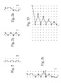
- Known methods for producing textile articles with warp-knitting machines include a series of basic operating steps, which allow to produce various types of knitting stitches, such as the well known basic stitches referred to as "pillar stitch” (shown in Figure 2 ), “tricot” (shown in Figure 2a ), “atlas lapping” and others. Beyond such basic stitches, other stitches deriving from the combination of specific shog movements of the thread-guide bar during the underlap and overlap movements and corresponding individual movements of single jacquard thread-guides in addition to the shog movement or in deduction from it, can be obtained. Two examples of known stitches deriving from such combinations of movements are shown in Figures 2b and 2c .
- An aim of the present invention is to overcome the limits of the prior art by proposing a method for producing textile articles with warp-knitting machines and a warp-knitting machine without the drawbacks described.
- a particular aim of the present invention is to provide a method and the corresponding equipment for producing fabrics characterized by more complex and complete jacquard patterns than the prior art, in a swift and economic manner.
- Another aim of the present invention is to propose a warp-knitting machine enabling to carry out such a method, which is compact and has a limited number of components so as to be advantageous in terms of costs, life time and simplified management of said machine.
- a further aim of the present invention is to disclose a warp-knitting machine which is extremely accurate, with minimized clearances between the various components, so as to allow the implementation of such a method with high speeds (high dynamics), and which is simple to carry out and low-cost.
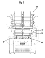
- a warp-knitting machine 50 comprises a control device 1 for thread-guide 3 bars 2, provided with a linear motor 10 apt to transmit a shog translational motion, referred to with numeral 4, to the thread-guide bar 2, means 40 for moving the thread-guide bar 2 according to a swing oscillating motion, referred to with numeral 5 and basically perpendicular to said translational motion, and transmission means 20 for transmitting to the thread-guide bar 2 the translational motion transmitted by the linear motor 10, thus enabling said bar 2 to move with an oscillating motion.
- a control device 1 for thread-guide 3 bars 2 provided with a linear motor 10 apt to transmit a shog translational motion, referred to with numeral 4, to the thread-guide bar 2, means 40 for moving the thread-guide bar 2 according to a swing oscillating motion, referred to with numeral 5 and basically perpendicular to said translational motion, and transmission means 20 for transmitting to the thread-guide bar 2 the translational motion transmitted by the linear motor 10, thus enabling said bar 2 to
- the device 1 is characterized in that the transmission means 20 comprise a first transmission element 21 associated and integral with the linear motor 10, and a second transmission element 24 that can be integrally associable with the thread-guide bar 2.
- the first transmission element 21 further has a first guide 22 inside which the second transmission element 24 is movably engaged.
- the second element 24 could have the first guide 22 and the first element 21 could be movably engaged inside said guide.
- the first guide 22 advantageously has a basically curved shape, so as to allow the oscillating motion of the thread-guide bar 2.
- the first transmission element 21 has an inner cavity 23 having at least a basically curved shape so as to represent said guide 22 for the second transmission element 24, as can be seen in Figure 5 , 7A , 7B and 8 .
- Such element 24 has in its turn a first end portion 25 matching said cavity 23 so as to oscillate within it and enable the oscillating motion.
- said cavity 23 is defined by two distinct portions 21a of the first transmission element 21, apt to enclose the first end portion 25 of the second transmission element 24.
- such cavity 23 has a quadrilateral side section and a curved front section
- the second transmission element 24 has a quadrilateral side section and a circular front section, so as to slide inside said cavity 23.
- the transmission means 20 also comprise a plurality of spheres 28 placed between the first 21 and the second 24 transmission element on the cavity 23 ( Figure 5 ).
- these means 20 comprise a plurality of fastening elements 29 apt to increase pressure between the first transmission element 21, the second transmission element 24 and the spheres 28 on the (preloaded) cavity 23 so as to minimize clearances between the first 21 and the second 24 transmission element.
- the fastening elements 29 comprise screws associated with the first transmission element 21 so that their middle axis is basically parallel to the one of the first element 21, thus ensuring the fastening of such element 21 to the motor 10.
- the space between the first 21 and the second 24 element on the cavity 23 is minimized but the radial sliding between the two elements 21, 24 is ensured by the action of the spheres 28.
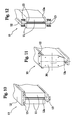
- the transmission means 20 further comprise an interface plate 30 fastened to the linear motor 10 and shown in detail in Figure 11 .
- the first transmission element 21 is therefore associated with the motor 10 by means of said interface plate 30 and also the fastening elements 29 are associated with the interface plate 30.
- the second transmission element 24 is integrally associated with the thread-guide bar 2 by means of its second end portion 26 ( Figures 5 , 7A and 7B ). Such element 24 further has a middle axis 27 which is always parallel to a direction of the translational motion, i.e. also to the middle axis of the first transmission element 21 and to the one of the motor 10.
- the linear motor 10 has at least a fixed part 11 and a moving part 12.
- the fixed part 11 comprises coils apt to generate an electromagnetic field when an electric current passes through them, and the moving part 12 comprises magnets that are sensitive to such electromagnetic field.
- the moving part 12 is moved so as to generate the translational motion to be transmitted to the thread-guide bar 2 as a result of the action of said electromagnetic field upon said magnets.
- the moving part 12 of the motor 10 that transmits to the thread-guide bar 2 the translational motion through the transmission means 20.
- the interface plate 30 or, if no interface plate 30 is present, the first transmission element 21 are fastened to an end portion 12a of the moving part 12 of the motor 10.
- the end portion 12a of the moving part 12 of the motor 10 can therefore have any shape provided that it enables the fastening to an interface plate 30 or, if required, to the first transmission element 21.
- the linear motor 10 of the device 1 according to the present invention can also have the coils associated with the moving part 12 and the magnets associated with the fixed part 11. In this case, however, the reciprocal movement of the two parts would be more difficult since the electric supply cables should be associated with the moving part 12 and would therefore be continuously subject to shifts and vibrations.
- the motor 10 employed is a horizontal, linear iron-core motor piloted with 540 V direct current or with 110 V to 220 V alternated current, with fixed supply cables (since these are associated with the fixed part 11 of the motor 10).
- the motor 10 is characterized in that its moving part 12 is basically T-shaped and is placed between at least two fixed parts 11.
- the overall size of the motor 10 can thus be highly reduced, especially in the area contacting the thread-guide bar 2, overcoming the strong limitation of known devices due to the huge size difference between the moving part 12 of the motor 10 and the thread-guide bar 2.
- the motor 10 can be potentiated by increasing its length and therefore its longitudinal extension, both for the fixed part 11 and for the moving part 12, so as to be able to use the device 1 also in applications requiring a high power.
- the moving part 12 of the motor 10 is basically shaped as a double T and generally the upper horizontal portion of the T has a larger front extension than the lower portion, still to minimize the front size of the motor 10 with respect to the thread-guide bar 2 ( Figures 6 , 10 and 11 ).
- a I-shape of the moving part 12 is however as suitable as the previous one for reducing the size difference between the motor 10 and the corresponding thread-guide bar 2, as shown in Figures 9A, 9B and 12 .
- the reduction of the front size difference between the motor 10 and the corresponding thread-guide bar 2 enables the motor 10 to work remaining always aligned with the corresponding bar 2.
- the motor 10 whatever the shape of its moving part 12, comprises at least a second sliding guide 13 for the moving part 12.
- the motor 10 is equipped with at least two of said sliding guides 13 placed between the fixed part 11 and the moving one 12.
- Said guides 13 have the function to simplify the translational sliding of the moving part 12 with respect to the fixed one 11, to minimize their mutual distance (referred to as air gap) and therefore the overall size of the motor 10, preventing said moving part 12 from swinging laterally with the motor 10 on or off, thus making coils and magnets collide in the most extreme cases.
- the motor 10 is associated with very accurate sliding guides 13 having spheres or migration crossing, preloaded, opposed or similar rollers.
- the device 1 can comprise detection means (not shown) acting upon the motor 10 to steer and control the movement of the moving part 12 with respect to the fixed one 11.
- detection means comprise at least one accurate linear position transducer either of magnetic, optical, variable-reluctance etc. type.
- the fixed part 11 of the motor 10 is generally anchored to a housing body acting as supporting frame also for the other parts of the motor 10.
- the means 40 for moving the thread-guide bar 2 according to the oscillating movement are associated and cooperate with the transmission means 20.
- the movement means 40 and the transmission means 20 are further advantageously mutually integrated and placed between the motor 10 and the thread-guide bar 2.
- the movement means 40 comprise a support 41 apt to move with oscillating motion around an axis of rotation 42, slidingly associated with the second transmission element 24 on at least a first engagement portion 43.
- Such support 41 further has a second engagement portion 44 with which the second transmission element 24 is still slidingly associated for stiffly transmitting the oscillating motion to the thread-guide bar 2.
- the support 41 is engaged with the second transmission element 24 on the first 43 and the second 44 engagement portion by means of sliding sleeves 45 which enable the second transmission element 24 to move with translational motion even if the support 41 is fixed with respect to the translation and only makes an oscillating movement.
- the second transmission element 24 can therefore be basically L- or T-shaped and be directly connected to the thread-guide bar 2 and to the support 41 on the two engagement portions 43, 44 mentioned above.
- the device 1 can comprise a prop element 46 integrally connected to the thread-guide bar 2 and to the second transmission element 24 on its second end portion 26, preferably so that the middle axis of the second transmission element 24 is basically parallel to the one of the thread-guide bar 2 and the middle axis of the prop element 46 is basically perpendicular thereto ( Figures 4 , 5 , 6 , 7A , 7B , 9A and 9B ).
- the support 41 is connected to the prop element 46 on the first engagement portion 43 by means of a sleeve 45, and to the second transmission element 24, still by means of a sleeve 45, on the second engagement portion 44.
- the device 1 is equipped with a first sleeve 45 associated with the prop element 46 on the first engagement portion 43 of the support 41, and with a second sleeve 45 associated with said support 41 on the second engagement portion 44.
- the two sleeves 45 are opposed to one another, as can be seen in Figures 7A and 7B .
- the present invention further protects a device 1 having a support 41 apt to move with oscillating motion and associated with a transmission element 24 on two engagement portions 43, 44, preferably by means of sleeves 45, so as to stiffly transmit to the thread-guide bars 2 an oscillating motion and to enable the translational motion, wherein the transmission element 24 is associated with a motor 10 by means of known systems such as articulated rods.
- the linear motor 10 transmits through its moving part 12 a translational motion to the first transmission element 21 by means of the interface plate 30. Such translational motion is then transmitted to the second transmission element 24, which is stiff and integral to translation with respect to the first transmission element 21. Such second transmission element 24 transmits in its turn the translational motion to the thread-guide bar 2 through the prop element 46, to which these two components 24, 46 are stiffly connected. Thanks to the translational motion transmitted by the motor 10, the thread-guide bar 2 can execute the shog movement and, thus, can move in front of the hook of each needle.
- the thread-guide bar 2 should also make the swing movement so as to move to the side of each needle and allow the thread associated with each thread-guide to be correctly fed.
- the swing movement is generated by the oscillating movement of the support 41. Thanks to the connection of said support 41 to the second transmission element 24 and to the prop element 46 on the first 43 and second 44 engagement portion, such oscillating movement is stiffly transmitted from the support 41 to the thread-guide bar 2.
- the second transmission element 24 and the prop element 46 are connected to the support 41 on the two engagement portions 43, 44 by means of sleeves 45 enabling the thread-guide bar 2 to stiffly move with oscillating motion with respect to said support 41 and enabling at the same time the second transmission element 24, the prop element 46 and the bar 2 to move with the translational motion transmitted by the motor 10.
- the inventive idea of the present invention further includes a linear knitting machine 50 characterized in that it comprises at least one control device 1 for thread-guide bars 2 as described above.
- a linear knitting machine 50 comprises a plurality of the control devices 1 described, since each of said devices 1 is associated with a thread-guide bar 2, each knitting machine including as a rule more than one, generally four to ten, of said bars.
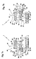
- the motors 10 of each device 1 are placed in a radial arrangement so as to basically build an arc in a plane basically parallel to the oscillating plane of the thread-guide bar 2, thus enabling the maximum approach between each of the motors 10 and the corresponding bar 2, as can be seen in Figures 4 , 6 , 9A and 9B .
- a first set of devices 1 ( Figure 9A ) is associated with one of the two end portions 2a of the bars 2, whereas a second set of devices 1 ( Figure 9B ) is associated with the opposite end portion 2a.
- the control devices 1 are alternatively arranged on an end portion 2a of the bar 2 and on the opposite one, as can be seen in Figures 9A and 9B .
- the devices 1 in a machine 50 can have components, such as the interface plate 30 or the first transmission element 21, differing from one another since each device 1 should have its center of thrust and oscillation very close to the axis of the moving part 12 of the linear motor 10 for balancing stresses.
- the knitting machine 50 comprises at least a suitable number of prop elements 46 with respect to the number of thread-guide bars 2, and at least two supports 41 generating the oscillating motion.
- each of these two supports 41 is associated with each of the second transmission elements 24 of the devices 1 and, if required, also with each of the prop elements 46, whereas the other one is associated on an end portion 2a of the thread-guide bar 2 opposed to the one with which each device 1 is associated.
- each thread-guide bar 2 is associated with at least two prop elements 46 on each of the two end portions 2a, as well as with a central prop element 46 for better balancing the knitting machine 50.
- the linear knitting machine 50 has a so-called "portal" configuration and the motors 10 and the control devices 1 for the thread-guide bars 2 are equally located inside the two shoulders of the machine 50.
- a warp-knitting machine 50 for carrying out a method according to the present invention therefore comprises a first thread-guide 3 bar 2 of jacquard type (preferably a plurality of said bars 2), a first linear motor 10 (preferably a plurality of motors 10 connected to corresponding bars 2) apt to transmit a shog translational movement to the first thread-guide 3 bar 2, the first linear motor 10 being configured so as to vary the shift width of the first thread-guide 3 bar 2 at least between a first predefined width corresponding to a first predefined number of needle spaces of the knitting machine, and at least a second width corresponding to a second predefined number of needle spaces.
- the machine 50 further comprises said means 40 for moving the first thread-guide bar 2 according to a swing oscillating motion transversal to the translational motion, and said transmission means 20 for transmitting to the first thread-guide bar 2 the translational motion of the first linear motor 10, thus enabling the oscillating motion.
- the machine 50 further comprises control means 60 (not described in detail since of conventional type, advantageously operatively connected to the general control means 51 of the machine 50) connected to linear motor 10 and programmable for setting, selecting and/or varying automatically the width of the shog movement of the first thread-guide bar, and further connected to the first jacquard thread-guide 3 bar 2 so as to further control the individual movements of the thread-guides 3 of the first bar 2, also in a coordinated manner with the width variations of the shog movement of the first thread-guide 3 bar 2.
- control means 60 not described in detail since of conventional type, advantageously operatively connected to the general control means 51 of the machine 50
- linear motor 10 and programmable for setting, selecting and/or varying automatically the width of the shog movement of the first thread-guide bar, and further connected to the first jacquard thread-guide 3 bar 2 so as to further control the individual movements of the thread-guides 3 of the first bar 2, also in a coordinated manner with the width variations of the shog movement of the first thread-guide
- the thread-guide 3 bars 2 can be provided with jacquard devices 6 of piezoelectric (such as those shown in Figures 4 and 4a ) or pneumatic type, but in a less preferred embodiment they could also be provided with mechanical jacquard devices.
- the linear motor 10 is configured so as to vary the shift width of the first thread-guide bar 2 between a first and second predefined width, differing from one another of a plurality of needle spaces, preferably of at least five needle spaces, and still more preferably of at least ten needle spaces.
- the first and the second predefined width could differ of at least twenty needle spaces, and preferably of at least fifty needle spaces.
- the needle spaces indicated above refer for instance to a machine with a GG24 fineness, i.e. 24 needle per inch.
- the same absolute value of shift in inches has different effects depending on the machine fineness, and obviously the extent of shift is related to number of needle spaces with which the bar should shift according to the method and to the size of the single needle space, deriving from the machine fineness.
- a method for producing textile articles with warp-knitting machines comprising a plurality of steps of shifting at least a first thread-guide 3 bar 2 of jacquard type with shog translational movements and with swing movements transversal and alternated to shog movements, so as to produce the textile articles on at least one needle bed 52 of the knitting machine 50.
- the needles of the needle bed 52 in the preferred embodiment two needle beds 52, not shown in detail in the figures since it is of known type like the remaining parts of the machine 50 that are not shown, can be of latch or compound type.
- the method according to the present invention further includes the steps of shifting at least said first thread-guide bar 2 by means of a corresponding first linear motor 10, with a shog movement of a first predefined width corresponding to a first predefined number of needle spaces, varying automatically through control means 60 connected to said linear motor 10 the shift controlled by the first linear motor 10 so as to vary the width of the shog movement during the production of the textile articles, and shifting at least the first thread-guide 3 bar 2 by means of the first linear motor 10 with a shog movement having a second predefined width, different from the first predefine width and corresponding to a second predefined number of needle spaces.
- the method includes the step of shifting a plurality of bars 2 of jacquard type, by means of a corresponding plurality of linear motors 10, of said first and second shog movement.
- the first and second predefined width differ of a plurality of needle spaces, i.e. for instance at least five needle spaces, preferably at least ten needle spaces. Still more preferably, they can differ of at least twenty needle spaces or of at least fifty needle spaces.
- the width of the shog movement of the jacquard thread-guide 3 bar 2 it is possible to define freely and without any manual intervention the width of the shog movement of the jacquard thread-guide 3 bar 2, thus obtaining any desired shift (with suitable linear motors 10 such travel can be extended up to more or less one hundred needles and above, referred for instance to a machine with fineness 24) and being able to vary such shift in a completely free manner by suitably programming the control means 60.
- the shift of the bar in terms of number of needles is related to the machine fineness, the absolute shift being the same (for instance in inches).
- the size of the single needle space with which the bar shifts depends on the machine fineness, and therefore for instance with fineness 3 the size of a single needle space is eight times larger than the size of a needle space with fineness 24. Therefore, the same shift in absolute value in inches of the bar on a machine with fineness 3 corresponds to a shift in terms of needle spaces that is an eighth of the shift in needle spaces on a machine with fineness 24.
- the step of automatically varying the width of the shog movements is executed during the production of the same textile article, which is manufactured with a plurality of different shift widths of the first thread-guide 3 bar 2 during corresponding shog movements and with a plurality of individual shifts of the first thread-guide 3.
- the method further comprises the step of automatically controlling by means of the control means 60 connected to the first thread guide bar at least an individual shift of a needle space of at least a first thread-guide 3, and preferably of a plurality of thread-guides 3 (each with its specific individual movement which might differ from the one of the other thread-guides), at least of the first thread-guide 3 bar 2 of jacquard type, during at least one of said shog movements of the first and/or second predefined width.
- the individual shift can be in addition to, in the same direction, or in deduction from, in the opposite direction, the corresponding shog movement of the thread-guide bar.
- the method according to the present invention enables to freely vary the shift width of the shog movement of the thread-guide 3 bars 2, which is progressively increased in the example shown in the figure and which is combined in the first row and in the last row with an individual shift of the single jacquard thread-guide 3.
- the invention also relates to a textile article manufactured with the method and/or the machine 50 described, which is obtained by means of a plurality of shog shifts of a width varying of a plurality of needle spaces, and by means of a plurality of individual movements of jacquard-type thread-guides 3.
- Such textile knitted article can be provided with jacquard or transparent effects obtained with woven yarns or variously arranged and/or knitted floating yarns, and such yarns can be arranged horizontally, vertically and diagonally with other yarns concurring to fabric formation.
- the invention achieved important advantages.
- a method according to the present invention allows to manufacture fabrics characterized by more complex and complete jacquard patterns than the prior art, in a swift and economic manner. This results also from the possibility of varying automatically, rapidly and without manual interventions the width of the shog movement of the thread-guide bars within a very large width range.
- a warp-knitting machine according to the present invention is compact and has a significantly smaller number of components than other machines, which has advantages in terms of costs, machine simplicity and life time of components.
- the machine can work at high speeds with a good balancing of stresses and faulty operations are less likely to take place.
- the machine offers a highly working accuracy and ensures a high-quality finished product.
Landscapes
- Engineering & Computer Science (AREA)
- Textile Engineering (AREA)
- Knitting Machines (AREA)
- Treatment Of Fiber Materials (AREA)
Applications Claiming Priority (1)
| Application Number | Priority Date | Filing Date | Title |
|---|---|---|---|
| IT000115A ITBS20080115A1 (it) | 2008-06-04 | 2008-06-04 | Metodo per la produzione di articoli tessili su macchine per maglieria in catena e macchina per realizzare tale metodo |
Publications (2)
| Publication Number | Publication Date |
|---|---|
| EP2130962A1 true EP2130962A1 (de) | 2009-12-09 |
| EP2130962B1 EP2130962B1 (de) | 2016-01-13 |
Family
ID=40301618
Family Applications (1)
| Application Number | Title | Priority Date | Filing Date |
|---|---|---|---|
| EP09153467.7A Not-in-force EP2130962B1 (de) | 2008-06-04 | 2009-02-23 | Verfahren zur Herstellung von Textilartikeln mit Kettenwirkmaschinen und Maschine zur Durchführung eines solchen Verfahrens |
Country Status (5)
| Country | Link |
|---|---|
| US (1) | US7757519B2 (de) |
| EP (1) | EP2130962B1 (de) |
| JP (1) | JP2009293177A (de) |
| CN (1) | CN101638827B (de) |
| IT (1) | ITBS20080115A1 (de) |
Families Citing this family (5)
| Publication number | Priority date | Publication date | Assignee | Title |
|---|---|---|---|---|
| DE102009042213B3 (de) * | 2009-09-18 | 2011-03-24 | Karl Mayer Textilmaschinenfabrik Gmbh | Wirkmaschine |
| CN104294476B (zh) * | 2014-10-22 | 2016-05-11 | 浙江越剑机械制造有限公司 | 一种高速经编机开停车智能控制系统及其控制方法 |
| CN109837739A (zh) * | 2019-03-05 | 2019-06-04 | 广州市雅娜琪服装有限公司 | 一种抗菌羊毛针织面料的制备工艺 |
| EP3708702B1 (de) * | 2020-06-26 | 2022-07-13 | KARL MAYER STOLL R&D GmbH | Kettenwirkmaschine |
| JP7306526B1 (ja) * | 2022-04-08 | 2023-07-11 | カール マイヤー ストール アールアンドディー ゲーエムベーハー | 経編地の編成方法及び経編機 |
Citations (5)
| Publication number | Priority date | Publication date | Assignee | Title |
|---|---|---|---|---|
| JPS6392762A (ja) | 1986-09-30 | 1988-04-23 | 日本マイヤー株式会社 | 編織機における導糸針の変位装置 |
| GB2289063A (en) * | 1994-04-28 | 1995-11-08 | Mayer Textilmaschf | Method for manufacturing warp knitted fabric |
| DE19801601C1 (de) * | 1998-01-17 | 1999-03-25 | Mayer Textilmaschf | Kettenwirkmaschine, Verfahren zur Herstellung einer gemusterten Kettenwirkware und gemusterte Kettenwirkware |
| US20050284187A1 (en) * | 2004-06-29 | 2005-12-29 | Karl Mayer Textilmaschinenfabrik Gmbh | Guide bar drive in a knitting machine |
| EP1840254A2 (de) * | 2006-03-08 | 2007-10-03 | SANTONI S.p.A. | Steuervorrichtung für Fadenführerbarren von Flachkettenwirkmaschinen |
Family Cites Families (7)
| Publication number | Priority date | Publication date | Assignee | Title |
|---|---|---|---|---|
| IT1153279B (it) * | 1982-10-21 | 1987-01-14 | Comez Spa | Macchina tessile perfezionata per la formazione di tessuti di vari colori e disegni |
| DE3321733C2 (de) * | 1983-06-16 | 1985-06-20 | Karl Mayer Textil-Maschinen-Fabrik Gmbh, 6053 Obertshausen | Kettenwirkmaschine mit Jacquard-Lochnadeln |
| IT1222416B (it) * | 1987-07-31 | 1990-09-05 | Luigi Omodeo Zorini | Organo di comando per arpini di tubetti guidafilo in telai per galloni ad uncino |
| DE4001621A1 (de) * | 1990-01-20 | 1991-07-25 | Mayer Textilmaschf | Kettenwirkmaschine und verfahren zur herstellung von polware sowie zugehoerige polware |
| DE4020550C1 (en) * | 1990-06-28 | 1991-10-17 | Karl Mayer Textilmaschinenfabrik Gmbh, 6053 Obertshausen, De | Warp knitting machine with needle bed with guide bars - provides knitted goods with stable surface |
| DE4020549A1 (de) * | 1990-06-28 | 1992-01-09 | Mayer Textilmaschf | Gemusterte wirkware sowie verfahren und kettenwirkmaschine zu ihrer herstellung |
| DE4312706C2 (de) * | 1993-04-20 | 1996-07-25 | Mayer Textilmaschf | Kettenwirkware mit Pol sowie Verfahren und Kettenwirkmaschine zu deren Herstellung |
-
2008
- 2008-06-04 IT IT000115A patent/ITBS20080115A1/it unknown
-
2009
- 2009-02-23 EP EP09153467.7A patent/EP2130962B1/de not_active Not-in-force
- 2009-03-24 JP JP2009071660A patent/JP2009293177A/ja active Pending
- 2009-04-03 US US12/418,275 patent/US7757519B2/en not_active Expired - Fee Related
- 2009-05-25 CN CN2009101386959A patent/CN101638827B/zh not_active Expired - Fee Related
Patent Citations (6)
| Publication number | Priority date | Publication date | Assignee | Title |
|---|---|---|---|---|
| JPS6392762A (ja) | 1986-09-30 | 1988-04-23 | 日本マイヤー株式会社 | 編織機における導糸針の変位装置 |
| GB2289063A (en) * | 1994-04-28 | 1995-11-08 | Mayer Textilmaschf | Method for manufacturing warp knitted fabric |
| DE19801601C1 (de) * | 1998-01-17 | 1999-03-25 | Mayer Textilmaschf | Kettenwirkmaschine, Verfahren zur Herstellung einer gemusterten Kettenwirkware und gemusterte Kettenwirkware |
| US20050284187A1 (en) * | 2004-06-29 | 2005-12-29 | Karl Mayer Textilmaschinenfabrik Gmbh | Guide bar drive in a knitting machine |
| EP1840254A2 (de) * | 2006-03-08 | 2007-10-03 | SANTONI S.p.A. | Steuervorrichtung für Fadenführerbarren von Flachkettenwirkmaschinen |
| US7320233B2 (en) | 2006-03-08 | 2008-01-22 | Santoni S.P.A. | Control device for linear knitting machines thread-guide bars |
Also Published As
| Publication number | Publication date |
|---|---|
| CN101638827A (zh) | 2010-02-03 |
| JP2009293177A (ja) | 2009-12-17 |
| ITBS20080115A1 (it) | 2009-12-05 |
| EP2130962B1 (de) | 2016-01-13 |
| CN101638827B (zh) | 2012-11-21 |
| US20090301141A1 (en) | 2009-12-10 |
| US7757519B2 (en) | 2010-07-20 |
Similar Documents
| Publication | Publication Date | Title |
|---|---|---|
| CN1049028C (zh) | 生产提花经编织物的方法及经编机 | |
| JP5822918B2 (ja) | 組み込まれたカバー糸を有する織物材料を製織するための織機 | |
| US7757519B2 (en) | Method to produce textiles articles with warp-knitting machines and machine to carry out such a method | |
| US3221520A (en) | Double-needle-bed warp knitting machine | |
| US20070209402A1 (en) | Control device for linear knitting machines thread-guide bars | |
| JP5080113B2 (ja) | 直線編機 | |
| US3303670A (en) | Multi-slide guide-bar | |
| CN106222872A (zh) | 一种一出二提花经编机 | |
| KR100348690B1 (ko) | 경편기에서의무늬내는장치 | |
| CN203451779U (zh) | 一种分结构的宽幅提花经编机 | |
| GB2511484B (en) | Lace manufacturing method | |
| US4417456A (en) | Thread positioning apparatus for a warp knitting machine | |
| EP3272921B1 (de) | Verfahren zum stricken von kettengewirkstoff | |
| KR20190103042A (ko) | 이중 바 경편기 | |
| JP2016148124A (ja) | 経編生地の編成方法 | |
| US3247686A (en) | Guide bars for warp knitting machine | |
| CN109706613B (zh) | 拉舍尔贾卡经编机的驱动结构及其控制装置 | |
| US2921452A (en) | Knitting machines and operating mechanism therefor | |
| CN204625952U (zh) | 一种少梳栉的拉舍尔经编机 | |
| GB1483040A (en) | Seaming of fabrics | |
| US3831403A (en) | Device for producing simultaneously two separate fabrics rib on the same head of a rib knitting machine with two needle beds | |
| CN206089979U (zh) | 一种一出二提花经编机 | |
| CN113151973A (zh) | 一种多维提花经编机 | |
| US3355911A (en) | Warp-knitting machine | |
| TWI821672B (zh) | 經編針織機、滑針總成及用於生產彈性針織品之方法 |
Legal Events
| Date | Code | Title | Description |
|---|---|---|---|
| PUAI | Public reference made under article 153(3) epc to a published international application that has entered the european phase |
Free format text: ORIGINAL CODE: 0009012 |
|
| AK | Designated contracting states |
Kind code of ref document: A1 Designated state(s): AT BE BG CH CY CZ DE DK EE ES FI FR GB GR HR HU IE IS IT LI LT LU LV MC MK MT NL NO PL PT RO SE SI SK TR |
|
| AX | Request for extension of the european patent |
Extension state: AL BA RS |
|
| 17P | Request for examination filed |
Effective date: 20100527 |
|
| 17Q | First examination report despatched |
Effective date: 20100623 |
|
| AKX | Designation fees paid |
Designated state(s): AT BE BG CH CY CZ DE DK EE ES FI FR GB GR HR HU IE IS IT LI LT LU LV MC MK MT NL NO PL PT RO SE SI SK TR |
|
| GRAP | Despatch of communication of intention to grant a patent |
Free format text: ORIGINAL CODE: EPIDOSNIGR1 |
|
| INTG | Intention to grant announced |
Effective date: 20150727 |
|
| GRAS | Grant fee paid |
Free format text: ORIGINAL CODE: EPIDOSNIGR3 |
|
| GRAA | (expected) grant |
Free format text: ORIGINAL CODE: 0009210 |
|
| AK | Designated contracting states |
Kind code of ref document: B1 Designated state(s): AT BE BG CH CY CZ DE DK EE ES FI FR GB GR HR HU IE IS IT LI LT LU LV MC MK MT NL NO PL PT RO SE SI SK TR |
|
| REG | Reference to a national code |
Ref country code: GB Ref legal event code: FG4D |
|
| REG | Reference to a national code |
Ref country code: CH Ref legal event code: EP |
|
| REG | Reference to a national code |
Ref country code: IE Ref legal event code: FG4D |
|
| REG | Reference to a national code |
Ref country code: AT Ref legal event code: REF Ref document number: 770593 Country of ref document: AT Kind code of ref document: T Effective date: 20160215 |
|
| REG | Reference to a national code |
Ref country code: DE Ref legal event code: R096 Ref document number: 602009035780 Country of ref document: DE |
|
| PGFP | Annual fee paid to national office [announced via postgrant information from national office to epo] |
Ref country code: TR Payment date: 20160328 Year of fee payment: 8 Ref country code: IT Payment date: 20160224 Year of fee payment: 8 Ref country code: DE Payment date: 20160301 Year of fee payment: 8 |
|
| REG | Reference to a national code |
Ref country code: LT Ref legal event code: MG4D |
|
| REG | Reference to a national code |
Ref country code: NL Ref legal event code: MP Effective date: 20160113 |
|
| PG25 | Lapsed in a contracting state [announced via postgrant information from national office to epo] |
Ref country code: BE Free format text: LAPSE BECAUSE OF NON-PAYMENT OF DUE FEES Effective date: 20160229 |
|
| REG | Reference to a national code |
Ref country code: AT Ref legal event code: MK05 Ref document number: 770593 Country of ref document: AT Kind code of ref document: T Effective date: 20160113 |
|
| PG25 | Lapsed in a contracting state [announced via postgrant information from national office to epo] |
Ref country code: NL Free format text: LAPSE BECAUSE OF FAILURE TO SUBMIT A TRANSLATION OF THE DESCRIPTION OR TO PAY THE FEE WITHIN THE PRESCRIBED TIME-LIMIT Effective date: 20160113 |
|
| PG25 | Lapsed in a contracting state [announced via postgrant information from national office to epo] |
Ref country code: NO Free format text: LAPSE BECAUSE OF FAILURE TO SUBMIT A TRANSLATION OF THE DESCRIPTION OR TO PAY THE FEE WITHIN THE PRESCRIBED TIME-LIMIT Effective date: 20160413 Ref country code: HR Free format text: LAPSE BECAUSE OF FAILURE TO SUBMIT A TRANSLATION OF THE DESCRIPTION OR TO PAY THE FEE WITHIN THE PRESCRIBED TIME-LIMIT Effective date: 20160113 Ref country code: FI Free format text: LAPSE BECAUSE OF FAILURE TO SUBMIT A TRANSLATION OF THE DESCRIPTION OR TO PAY THE FEE WITHIN THE PRESCRIBED TIME-LIMIT Effective date: 20160113 Ref country code: ES Free format text: LAPSE BECAUSE OF FAILURE TO SUBMIT A TRANSLATION OF THE DESCRIPTION OR TO PAY THE FEE WITHIN THE PRESCRIBED TIME-LIMIT Effective date: 20160113 Ref country code: GR Free format text: LAPSE BECAUSE OF FAILURE TO SUBMIT A TRANSLATION OF THE DESCRIPTION OR TO PAY THE FEE WITHIN THE PRESCRIBED TIME-LIMIT Effective date: 20160414 |
|
| PG25 | Lapsed in a contracting state [announced via postgrant information from national office to epo] |
Ref country code: SE Free format text: LAPSE BECAUSE OF FAILURE TO SUBMIT A TRANSLATION OF THE DESCRIPTION OR TO PAY THE FEE WITHIN THE PRESCRIBED TIME-LIMIT Effective date: 20160113 Ref country code: PT Free format text: LAPSE BECAUSE OF FAILURE TO SUBMIT A TRANSLATION OF THE DESCRIPTION OR TO PAY THE FEE WITHIN THE PRESCRIBED TIME-LIMIT Effective date: 20160513 Ref country code: LV Free format text: LAPSE BECAUSE OF FAILURE TO SUBMIT A TRANSLATION OF THE DESCRIPTION OR TO PAY THE FEE WITHIN THE PRESCRIBED TIME-LIMIT Effective date: 20160113 Ref country code: IS Free format text: LAPSE BECAUSE OF FAILURE TO SUBMIT A TRANSLATION OF THE DESCRIPTION OR TO PAY THE FEE WITHIN THE PRESCRIBED TIME-LIMIT Effective date: 20160513 Ref country code: LT Free format text: LAPSE BECAUSE OF FAILURE TO SUBMIT A TRANSLATION OF THE DESCRIPTION OR TO PAY THE FEE WITHIN THE PRESCRIBED TIME-LIMIT Effective date: 20160113 Ref country code: PL Free format text: LAPSE BECAUSE OF FAILURE TO SUBMIT A TRANSLATION OF THE DESCRIPTION OR TO PAY THE FEE WITHIN THE PRESCRIBED TIME-LIMIT Effective date: 20160113 Ref country code: AT Free format text: LAPSE BECAUSE OF FAILURE TO SUBMIT A TRANSLATION OF THE DESCRIPTION OR TO PAY THE FEE WITHIN THE PRESCRIBED TIME-LIMIT Effective date: 20160113 |
|
| REG | Reference to a national code |
Ref country code: CH Ref legal event code: PL |
|
| REG | Reference to a national code |
Ref country code: DE Ref legal event code: R097 Ref document number: 602009035780 Country of ref document: DE |
|
| PG25 | Lapsed in a contracting state [announced via postgrant information from national office to epo] |
Ref country code: CH Free format text: LAPSE BECAUSE OF NON-PAYMENT OF DUE FEES Effective date: 20160229 Ref country code: LI Free format text: LAPSE BECAUSE OF NON-PAYMENT OF DUE FEES Effective date: 20160229 Ref country code: MC Free format text: LAPSE BECAUSE OF FAILURE TO SUBMIT A TRANSLATION OF THE DESCRIPTION OR TO PAY THE FEE WITHIN THE PRESCRIBED TIME-LIMIT Effective date: 20160113 Ref country code: DK Free format text: LAPSE BECAUSE OF FAILURE TO SUBMIT A TRANSLATION OF THE DESCRIPTION OR TO PAY THE FEE WITHIN THE PRESCRIBED TIME-LIMIT Effective date: 20160113 Ref country code: EE Free format text: LAPSE BECAUSE OF FAILURE TO SUBMIT A TRANSLATION OF THE DESCRIPTION OR TO PAY THE FEE WITHIN THE PRESCRIBED TIME-LIMIT Effective date: 20160113 |
|
| PLBE | No opposition filed within time limit |
Free format text: ORIGINAL CODE: 0009261 |
|
| STAA | Information on the status of an ep patent application or granted ep patent |
Free format text: STATUS: NO OPPOSITION FILED WITHIN TIME LIMIT |
|
| REG | Reference to a national code |
Ref country code: FR Ref legal event code: ST Effective date: 20161028 |
|
| PG25 | Lapsed in a contracting state [announced via postgrant information from national office to epo] |
Ref country code: SK Free format text: LAPSE BECAUSE OF FAILURE TO SUBMIT A TRANSLATION OF THE DESCRIPTION OR TO PAY THE FEE WITHIN THE PRESCRIBED TIME-LIMIT Effective date: 20160113 Ref country code: CZ Free format text: LAPSE BECAUSE OF FAILURE TO SUBMIT A TRANSLATION OF THE DESCRIPTION OR TO PAY THE FEE WITHIN THE PRESCRIBED TIME-LIMIT Effective date: 20160113 Ref country code: RO Free format text: LAPSE BECAUSE OF FAILURE TO SUBMIT A TRANSLATION OF THE DESCRIPTION OR TO PAY THE FEE WITHIN THE PRESCRIBED TIME-LIMIT Effective date: 20160113 |
|
| REG | Reference to a national code |
Ref country code: IE Ref legal event code: MM4A |
|
| 26N | No opposition filed |
Effective date: 20161014 |
|
| GBPC | Gb: european patent ceased through non-payment of renewal fee |
Effective date: 20160413 |
|
| PG25 | Lapsed in a contracting state [announced via postgrant information from national office to epo] |
Ref country code: BE Free format text: LAPSE BECAUSE OF FAILURE TO SUBMIT A TRANSLATION OF THE DESCRIPTION OR TO PAY THE FEE WITHIN THE PRESCRIBED TIME-LIMIT Effective date: 20160113 |
|
| PG25 | Lapsed in a contracting state [announced via postgrant information from national office to epo] |
Ref country code: GB Free format text: LAPSE BECAUSE OF NON-PAYMENT OF DUE FEES Effective date: 20160413 Ref country code: FR Free format text: LAPSE BECAUSE OF NON-PAYMENT OF DUE FEES Effective date: 20160314 Ref country code: IE Free format text: LAPSE BECAUSE OF NON-PAYMENT OF DUE FEES Effective date: 20160223 |
|
| PG25 | Lapsed in a contracting state [announced via postgrant information from national office to epo] |
Ref country code: BG Free format text: LAPSE BECAUSE OF FAILURE TO SUBMIT A TRANSLATION OF THE DESCRIPTION OR TO PAY THE FEE WITHIN THE PRESCRIBED TIME-LIMIT Effective date: 20160413 Ref country code: SI Free format text: LAPSE BECAUSE OF FAILURE TO SUBMIT A TRANSLATION OF THE DESCRIPTION OR TO PAY THE FEE WITHIN THE PRESCRIBED TIME-LIMIT Effective date: 20160113 |
|
| PG25 | Lapsed in a contracting state [announced via postgrant information from national office to epo] |
Ref country code: MT Free format text: LAPSE BECAUSE OF FAILURE TO SUBMIT A TRANSLATION OF THE DESCRIPTION OR TO PAY THE FEE WITHIN THE PRESCRIBED TIME-LIMIT Effective date: 20160113 |
|
| REG | Reference to a national code |
Ref country code: DE Ref legal event code: R119 Ref document number: 602009035780 Country of ref document: DE |
|
| PG25 | Lapsed in a contracting state [announced via postgrant information from national office to epo] |
Ref country code: DE Free format text: LAPSE BECAUSE OF NON-PAYMENT OF DUE FEES Effective date: 20170901 |
|
| PG25 | Lapsed in a contracting state [announced via postgrant information from national office to epo] |
Ref country code: IT Free format text: LAPSE BECAUSE OF NON-PAYMENT OF DUE FEES Effective date: 20170223 |
|
| PG25 | Lapsed in a contracting state [announced via postgrant information from national office to epo] |
Ref country code: CY Free format text: LAPSE BECAUSE OF FAILURE TO SUBMIT A TRANSLATION OF THE DESCRIPTION OR TO PAY THE FEE WITHIN THE PRESCRIBED TIME-LIMIT Effective date: 20160113 Ref country code: HU Free format text: LAPSE BECAUSE OF FAILURE TO SUBMIT A TRANSLATION OF THE DESCRIPTION OR TO PAY THE FEE WITHIN THE PRESCRIBED TIME-LIMIT; INVALID AB INITIO Effective date: 20090223 |
|
| PG25 | Lapsed in a contracting state [announced via postgrant information from national office to epo] |
Ref country code: MK Free format text: LAPSE BECAUSE OF FAILURE TO SUBMIT A TRANSLATION OF THE DESCRIPTION OR TO PAY THE FEE WITHIN THE PRESCRIBED TIME-LIMIT Effective date: 20160113 Ref country code: MT Free format text: LAPSE BECAUSE OF FAILURE TO SUBMIT A TRANSLATION OF THE DESCRIPTION OR TO PAY THE FEE WITHIN THE PRESCRIBED TIME-LIMIT Effective date: 20160229 Ref country code: LU Free format text: LAPSE BECAUSE OF NON-PAYMENT OF DUE FEES Effective date: 20160223 |
|
| PG25 | Lapsed in a contracting state [announced via postgrant information from national office to epo] |
Ref country code: TR Free format text: LAPSE BECAUSE OF NON-PAYMENT OF DUE FEES Effective date: 20170223 |