EP1840254A2 - Steuervorrichtung für Fadenführerbarren von Flachkettenwirkmaschinen - Google Patents
Steuervorrichtung für Fadenführerbarren von Flachkettenwirkmaschinen Download PDFInfo
- Publication number
- EP1840254A2 EP1840254A2 EP07102917A EP07102917A EP1840254A2 EP 1840254 A2 EP1840254 A2 EP 1840254A2 EP 07102917 A EP07102917 A EP 07102917A EP 07102917 A EP07102917 A EP 07102917A EP 1840254 A2 EP1840254 A2 EP 1840254A2
- Authority
- EP
- European Patent Office
- Prior art keywords
- thread
- transmission element
- guide bar
- motor
- guide
- Prior art date
- Legal status (The legal status is an assumption and is not a legal conclusion. Google has not performed a legal analysis and makes no representation as to the accuracy of the status listed.)
- Granted
Links
Images




Classifications
-
- D—TEXTILES; PAPER
- D04—BRAIDING; LACE-MAKING; KNITTING; TRIMMINGS; NON-WOVEN FABRICS
- D04B—KNITTING
- D04B27/00—Details of, or auxiliary devices incorporated in, warp knitting machines, restricted to machines of this kind
- D04B27/10—Devices for supplying, feeding, or guiding threads to needles
- D04B27/24—Thread guide bar assemblies
- D04B27/26—Shogging devices therefor
Definitions
- the present invention relates to a control device for thread-guide bars of linear knitting machines such as Raschel-type warp looms and the like.
- linear knitting machines are provided with a plurality of bars designed to carry a plurality of thread-holding elements commonly known as thread-guides. Said bars should be handled so as to enable the threads associated to said thread-guides to be correctly fed onto the needles of the knitting machine for the formation of new fabric with the well-known technique in which the new thread enters the old loop and the old loop is discharged and becomes part of the fabric being formed.
- the thread-guide bar makes two basic movements simultaneously, i.e. a first linear movement in front of the hook of each needle, commonly known as “shog”, and an oscillating movement on the side of each needle for bringing the threads alternatively before and behind the needle hook, commonly known as “swing”.
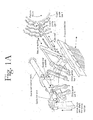
- a first example of known control devices for thread-guide bars on linear knitting machines are of mechanical type. These systems are disclosed for instance in handbooks that are generally known in the textile field, such as " Knitting Technology” by D.J. Spencer (Pergamon Press 1989 2nd edition) Figure 2 page 266 , shown in the accompanying drawings as Figure 1A, and " Warp Knit Machine Elements” by C. Wilkens (U. Wilkens Verlag, Heusenstamm Germany 1997) Figure 2.2.1 page 16 and Figure 7.1.2 page 55 .
- Such systems generally include a drum with fixed cams (or in the form of a chain), which turns around its axis and causes the shift of a lever pivoting on another axis and connected in its turn to a jointed system connected to the thread-guide bar.
- the return of the thread-guide bar is achieved by means of strong springs connected to the bar, which take the bar back to its initial position so as to receive another forward thrust by the following cam located on the turning drum.
- the rod pushing the bar forward should necessarily be jointed so as to enable also the oscillating movement imparted to the thread-guide bar by the support to which it is anchored.
- the drum is made up of a system including a control motor, usually a brushless or stepping motor, so as to partially solve the drawbacks pointed out, as shown in document US 6,959,566 , in particular in Figure 1.
- said motor can move a crank connected to its axis of rotation and to a jointed rod (connecting rod), which is in turn connected to the thread-guide bar.
- the motor with its oscillating motion makes a movement both of forward thrust and of backward thrust of the jointed rod, and therefore there is no need to use return springs.
- Brushless motors were developed for making complete rotations and, moreover, the maximum transmitted torque occurs from a given number of revolutions, typically from 2.000-3.000 revolutions.
- limited portions of round angle are used, generally of about ⁇ 5°-10°.
- Each motor is piloted in a sophisticated manner so as to make the angular shifts of its axis correspond to linear shifts of the thread-guide bar.
- stepping motors instead of brushless motors gives rise to some problems that should not be neglected.
- said motors can make in one revolution a given number of angular positions, typically 200. Accordingly, the positions in which the motor can be stopped are finite and depend on the number of steps characterizing the motor.
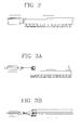
- FIG. 1B, 1C and 1D Another known system for the movement of thread-guide bars includes the use of a brushless motor (or, if necessary, of another suitable type of motor) with a pulley fitted thereon, around which is wound a steel band (for instance a sheet or a toothed belt), which can be connected to the thread-guide bar so as to pull the bar.
- the return movement of the thread-guide bar can be created by a return spring or by another similar system associated to the opposite end portion of the bar.
- FIG. 1B, 1C and 1D Such solution is shown in Figures 1B, 1C and 1D.
- linear actuators are used for converting the rotational movement of the motor into a linear movement.
- Such devices are characterized by a brushless or stepping motor onto whose transmission shaft is fitted an actuator in the form of a screw along which is placed a female thread connected directly and fastened to the element to be moved.
- These devices are shown in detail in Figure 7.1.4 of the handbook "Warp Knit Machine Elements” referred to above and in Figures 1, 3 and 4 of document US 2004/0261464 .
- the rotational movement of the transmission shaft turns the screw, which goes neither forward nor backward but pushes the female thread, and therefore the thread-guide bar, forward or backward.
- the fitting system between the transmission shaft and the screw can simply include a joint or a sophisticated reduction system, which after many revolutions of the motor makes the screw partly rotate on its axis.
- the system is generally provided with a sensor reading the position of the bar and transmitting it to the electronic system controlling movement.
- a further example of known control devices for thread-guide bars on linear knitting machines uses linear motors characterized in that they can be fitted directly onto the body to be moved without the need for intermediate elements for transmitting motion, and in that they can make rapid and accurate shifts with extremely low clearances, as shown in Figure 2.
- motors are characterized by the use of magnets obtained by synthesis of the so-called rare earths, mixed and combined together and then permanently magnetized with suitable techniques.
- the linear motor makes a movement both of forward thrust and backward thrust of the thread-guide bar without the help of return springs.
- Linear knitting machines have generally four to eight thread-guide bars, spaced one from the other and moving all together in oscillation and separately for forward and backward movements. As a consequence, the size of the machine is quite large since every thread-guide bar is associated to a linear motor, to a hydraulic amplification device, to a jointed connecting rod and to a dampening system.
- the front size ratio between the thread-guide bar and the motor is highly unbalanced since motors placed side by side generally occupy a surface that is approximately 10-15 times bigger than the surface of bars, and therefore no jointed rod works lined up with the thread-guide bar and the linear motor.
- the rods pivoting on the fixed motors describe each a different arc of circumference due to their misalignment with the motor. Therefore, every device should be adjusted so as to work accurately in the narrow spaces defined by needle shed (i.e. by the distance between the needles) so as to avoid the risk that needles located above intercept threads that should instead go through untouched, and form fabric when they should not and conversely. This also explains the reason why a motor should be associated to a single bar since its shift depends on the position of the bar in the group of bars.
- An aim of the present invention consists in solving the problems existing at the state of the art by proposing a control device for thread-guide bars of linear knitting machines that is not affected by the drawbacks described above.
- an aim of the present invention consists in proposing a control device for thread-guide bars of linear knitting machines that is compact and has a limited number of components so as to result in advantages as far as costs and service life are concerned, and to simplify the management of said machine.
- a further aim of the present invention consists in disclosing a control device for thread-guide bars of linear knitting machines that is extremely accurate and in which the clearances between the various components are minimized.
- Still another aim of the present invention consists in showing a control device for thread-guide bars of linear knitting machines that allows the bar to make both basic movements required for correctly feeding the thread onto the needles for the formation of new fabric.
- a further aim of the invention consists in providing a control device for thread-guide bars of linear knitting machines that enables high use speeds (high dynamics), that is simple to carry out and with low costs.
- an aim of the present invention consists in proposing a control device for thread-guide bars of linear knitting machines that enables to obtain high-quality finished items and to minimize the likelihood of positioning the thread outside the operating area.
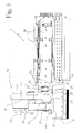
- a control device 1 for thread-guide bars 2 of linear knitting machines comprises a linear motor 10 designed to impart a translational motion to the thread-guide bar 2, means 40 for moving the thread-guide bar 2 according to an oscillating motion basically perpendicular to said translational motion, and transmission means 20 for transmitting to the thread-guide bar 2 the translational motion imparted by the linear motor 10, enabling said bar 2 to move with an oscillating motion.
- the device 1 is characterized in that the transmission means 20 comprise a first transmission element 21 associated to and integral with the linear motor 10, and a second transmission element 24 that can be associated integrally to the thread-guide bar 2.
- the first transmission element 21 further has a first guide 22 in which the second transmission element 24 is movably engaged.
- the first guide 22 has a basically curved shape so as to enable the oscillating motion of the thread-guide bar 2.
- the first transmission element 21 is provided with an inner recess 23 having at least a basically curved shape so as to represent said guide 22 for the second transmission element 24, as can be inferred from Figures 5, 7A, 7B and 8.
- Said element 24 is provided in its turn with a first end portion 25 matching said recess 23 so as to oscillate therein and enable the oscillating motion.
- said recess 23 is defined by two discrete portions 21a of the first transmission element 21.
- said recess 23 has a quadrilateral side section and a curved front section
- the second transmission element 24 has a quadrilateral side section and a circular front section so as to slide within the recess 23.
- the transmission means 20 also comprise a plurality of spheres 28 placed between the first 21 and the second transmission element 24 in the recess 23 ( Figure 5). Moreover, these means 20 comprise a plurality of fastening elements 29 designed to increase the pressure between the first transmission element 21, the second transmission element 24 and the spheres 28 in the recess 23 (preloading) so as to minimize clearances between the first 21 and the second transmission element 24.
- the fastening elements 29 include screws associated to the first transmission element 21 so as to have the middle axis basically parallel to the one of the first element 21 and thus ensure the fastening of said element 21 to the motor 10. As a result of the action of the screws, the space between the first 21 and the second element 24 in the recess 23 is minimized, but the radial sliding between the two elements 21, 24 is ensured by the action of the spheres 28.
- the transmission means 20 further include an interface plate 30 fastened to the linear motor 10 and shown in detail in Figure 11.
- the first transmission element 21 is thus associated to the motor 10 by means of said interface plate 30 and also the fastening elements 29 are associated to the interface plate 30.
- the second transmission element 24 is integrally associated to the thread-guide bar 2 by means of a second end portion 26 thereof (figure 5, 7A e 7B). Said element 24 further has a middle axis 27 that is always parallel to a direction of the translational motion, i.e. also to the middle axis of the first transmission element 21 and to the one of the motor 10.
- the linear motor 10 includes at least one fixed part 11 and a movable part 12.
- the fixed part 11 comprises coils designed to generate an electromagnetic field when an electric current gets through them, and the movable part 12 comprises magnets that are sensitive to said electromagnetic field.
- the movable part 12 is moved so as to generate the translational motion to be imparted to the thread-guide bar 2 as a result of said electromagnetic field acting upon said magnets.
- the movable part 12 of the motor 10 that transmits to the thread-guide bar 2 the translational motion through the transmission means 20.
- the interface plate 30 or the first transmission element 21, if no interface plate 30 is present are fastened to an end portion 12a of the movable part 12 of the motor 10.
- the end portion 12a of the movable part 12 of the motor 10 can therefore have any shape provided that the latter enables the fastening to an interface plate 30 or, if desired, to the first transmission element 21.
- the coils can be associated to the movable part 12 and the magnets to the fixed part 11.
- the reciprocal movement of the two parts would be more difficult since the electrical supply cables should be associated to the movable part 12 and would thus be subject to continuous shifts and vibrations.
- the motor 10 used is a iron-core horizontal linear motor piloted with direct current at 540 V or with alternate current at 110 V to 220 V, with fixed supply cables (since they are associated to the fixed part 11 of the motor 10).
- the motor 10 is characterized in that its movable part 12 is basically T-shaped and is placed between at least two fixed parts 11. It is thus possible to highly reduce the overall size of the motor 10, especially in the area getting in contact with the thread-guide bar 2, thus overcoming the severe limitation of known devices due to the significant size difference between the movable part 12 of the motor 10 and the thread-guide bar 2. Moreover, the motor 10 can be boosted by increasing its length and, therefore, the longitudinal extension, both of the fixed part 11 and of the movable part 12, so as to be able to use the device 1 also for applications requiring a high power.
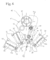
- the movable part 12 of the motor 10 is basically shaped as a double T, and generally the horizontal upper portion of the T has a larger front extension than the lower portion, still in order to minimize the front size of the motor 10 with respect to the thread-guide bar 2 ( Figures 6, 10 and 11).
- the I shape of the movable part 12, as shown in Figures 9A, 9B and 12, is as valid as the previous one. More to the point, it should be pointed out that the reduction of the front size difference between the motor 10 and the corresponding thread-guide bar 2 enables the motor 10 to operate in continuous alignment with the corresponding bar 2.
- the motor 10 whatever the shape of its movable part 12, comprises at least one second sliding guide 13 for the movable part 12.
- the motor 10 is equipped with at least two of said sliding guides 13 placed between the fixed part 11 and the movable part 12.
- Said guides 13 also simplify the translational sliding of the movable part 12 with respect to the fixed one 11 and minimize the mutual distance (known as air gap) and therefore the overall size of the motor 10, preventing the movable part 12 from swinging laterally with motor 10 on or off and, in extreme cases, letting coils and magnets crash with one another.
- the motor 10 is associated to very accurate sliding guides 13 with spheres or rollers that are crossed with migration and preloaded, opposed or the like.
- the device 1 can include detection means (not shown) acting upon the motor 10 so as to drive and control the movement of the movable part 12 with respect to the fixed one 11.
- said detection means comprise at least an accurate linear position transducer that can be magnetic, optical, with variable reluctance etc.
- the fixed part 11 of the motor 10 is generally anchored to a containing body (case) acting as supporting frame also for the other parts of the motor 10.
- the means 40 for moving the thread-guide bar 2 with the oscillating movement are associated to and cooperate with the transmission means 20.
- the means 40 for moving and the transmission means 20 are furthermore advantageously integrated with one another and placed between the motor 10 and the thread-guide bar 2.
- the means 40 for moving include a support 41 designed to move with an oscillating motion around an axis of rotation 42, slidingly associated to the second transmission element 24 on at least one first engagement portion 43.
- Said support 41 further has a second engagement portion 44 slidingly associated still to the second transmission element 24, so as to transmit stiffly the oscillating motion to the thread-guide bar 2.
- the support 41 is engaged to the second transmission element 24 on the first 43 and on the second engagement portion 44 by means of sliding sleeves 45 enabling the second transmission element 24 to move with a translational motion even if the support 41 is fixed with respect to the translation and makes only an oscillating movement.
- the second transmission element 24 can therefore be basically L- or T-shaped and be connected directly to the thread-guide bar 2 and to the support 41 on said two engagement portions 43, 44.
- the latter can comprise a supporting element 46 integrally connected to the thread-guide bar 2 and to the second transmission element 24, on its second end portion 26, preferably so that the middle axis of the second transmission element 24 is basically parallel to the one of the thread-guide bars 2 and that the middle axis of the supporting element 46 is basically perpendicular to both axes ( Figures 4, 5, 6, 7A, 7B, 9A and 9B).
- the support 41 is connected to the supporting element 46 on the first engagement portion 43, by means of a sleeve 45, and to the second transmission element 24, still by means of a sleeve 45, on the second engagement portion 44.
- the device 1 is provided with a first sleeve 45 associated to the supporting element 46 on the first engagement portion 43 of the support 41, and with a second sleeve 45 associated to said support 41 on the second engagement portion 44. Therefore, in this case the two sleeves 45 are opposed to one another, as can be seen in Figures 7A and 7B.
- the engagement between the second transmission element 24, and possibly between the supporting element 46, and the support 41 is highly innovative. It should thus be pointed out that the present invention also protects a device 1 having a support 41 designed to move with an oscillating motion and associated to a transmission element 24 on two engagement portion 43, 44, preferably by means of sleeves 45, so as to transmit stiffly to the thread-guide bars 2 an oscillating motion and enable the translational motion, wherein the transmission element 24 is associated to a motor 10 by means of known systems such as jointed rods.
- the linear motor 10 through its movable part 12, imparts a translational motion to the first transmission element 21 by means of the interface plate 30. Such translational motion is then transmitted to the second transmission element 24, which is stiff and integral in terms of translation with respect to the first transmission element 21. In its turn, said second transmission element 24 transmits the translational motion to the thread-guide bar 2 by means of the supporting element 46 to which these two components 24, 46 are stiffly connected. Thanks to the translational motion imparted by the motor 10, the thread-guide bar 2 can make the "shog" movement, thus moving frontally with respect to the hook of every needle.
- the thread-guide bar 2 should also make the “swing” movement so as to move laterally with respect to every needle and allow a correct feeding of the thread associated to each thread-guide.
- the "swing” movement is generated by the oscillating movement of the support 41. Thanks to the connection of said support 41 to the second transmission element 24 and to the supporting element 46 on the first 43 and on the second engagement portion 44, said oscillating movement is stiffly transmitted from the support 41 to the thread-guide bar 2.
- the second transmission element 24 and the supporting element 46 are connected to the support 41 on the two engagement portions 43, 44 by means of sleeves 45 enabling the thread-guide bar 2 to move stiffly with an oscillating movement with respect to said support 41 and, at the same time, enabling the second transmission element 24, the supporting element 46 and the bar 2 to move with the translational movement imparted by the motor 10.
- the inventive idea of the present invention also includes a linear knitting machine characterized in that it comprises at least one control device 1 for thread-guide bars 2 as described above.
- a linear knitting machine comprises a plurality of the control devices 1 as described above, since each of said devices 1 is associated to a thread-guide bar 2, conventionally being there more than one of them, generally four to ten, in each knitting machine.
- the motors 10 of every device 1 are arranged radially so as to describe basically an arc in a plane basically parallel to the oscillation plane of the thread-guide bars 2 and allow the maximum closeness between each of the motors 10 and the corresponding bar 2, as can be inferred from Figures 4, 6, 9A and 9B.
- a first group of devices 1 (Figure 9A) is associated to one of the two end portions 2a of the bars 2, whereas a second group of devices 1 ( Figure 9B) is associated to the opposite end portion 2a.
- control devices 1 are alternatively arranged on an end portion 2a of the bar and on the opposite one, as can be inferred from Figures 9A and 9B.
- the devices 1 on a machine can have components, such as the interface plate 30 or the first transmission element 21, differing from one another since every device 1 should have its thrust and oscillation center very close to the axis of the movable part 12 of the linear motor 10 so as to balance efforts.
- the knitting machine includes at least a number of supporting elements 46 matching the number of thread-guide bars 2 and at least two supports 41 generating the oscillating motion. More to the point, each of these two supports 41 is associated to each of the second transmission elements 24 of the devices 1 and, if necessary, also to each of the supporting elements 46, whereas the other one is associated on an opposite end portion 2a of the thread-guide bar 2 with respect to the one to which every device 1 is associated. Similarly, every thread-guide bar 2 is associated to at least two supporting elements 46 on each of the two end portions 2a and also to a central supporting element 46 for an improved balancing of the knitting machine.
- the linear knitting machine according to the present invention has a so-called "portal" shape, and the motors 10 and the control devices 1 for the thread-guide bars 2 are uniformly placed inside the two shoulders of the machine.
- the following description can apply for example both to warp machines of the raschel or tricot and similar types with thread-guide bars 2 having a length of about one meter and suitable for manufacturing ribbons, scarves etc., and to machines with bars 2 having a length above 3 m used for knitting clothing (stockings, pieces of cloth etc.).
- the invention achieves important advantages.
- the control device for thread-guide bars of linear knitting machines is compact and has a significantly smaller number of components than known devices having the same function, since the motor and the thread-guide bar are connected directly by means of the first and the second transmission element and, if desired, by means of the interface plate. This gives rise to advantages as far as costs are concerned, increases the simplicity of the machine and the service life of said components and reduces the likelihood of breaks and the overall size of the machine.
- the radial arrangement of the linear motors, some of them being in contact with an end portion of the bar and the other ones in contact with the other one, and the shape as a double T of the movable part of the motor have allowed to further reduce the overall size of the knitting machine and the front size unbalance between the motor and the thread-guide bar and to enhance the balance of efforts in the machine.
- the machine can operate at high speeds and failures are less likely to occur.
- the devices are structured and arranged inside the machine so that the oscillation and thrust centers for translation are basically lined up, thus enhancing the balance of efforts and, therefore, also the service life and the operation of said machine.
- the devices disclosed above have a high operating accuracy and eliminate the drawback of positioning the thread out of the operating trajectory, which often occurs with known devices, thus ensuring a high-quality finished item.
- transmission takes place only by means of the two transmission elements operating with axes that are always parallel to the one of the motor and of the thread-guide bar, and clearances are minimized both in the motor and in the transmission means (differently from known devices, see Figure 3B).
- the reduction in the number of components and their particular reciprocal shape has further made the machine less sensitive also to factors such as temperature.
- a further advantage consists in that the various components are uniformly distributed inside the machine, so as to exploit every space, reduce the overall size and have a balanced and rational structure enhancing its performance and simplifying for instance maintenance or modification operations.
- the particular shape of the motor enables to minimize its front size keeping the power it generated unchanged.
Landscapes
- Engineering & Computer Science (AREA)
- Textile Engineering (AREA)
- Knitting Machines (AREA)
- Treatment Of Fiber Materials (AREA)
- Preliminary Treatment Of Fibers (AREA)
Applications Claiming Priority (1)
| Application Number | Priority Date | Filing Date | Title |
|---|---|---|---|
| IT000056A ITBS20060056A1 (it) | 2006-03-08 | 2006-03-08 | Dispositivo di comando per barre porta passette di macchine tessili lineari |
Publications (3)
| Publication Number | Publication Date |
|---|---|
| EP1840254A2 true EP1840254A2 (de) | 2007-10-03 |
| EP1840254A3 EP1840254A3 (de) | 2009-10-21 |
| EP1840254B1 EP1840254B1 (de) | 2012-01-04 |
Family
ID=38335744
Family Applications (1)
| Application Number | Title | Priority Date | Filing Date |
|---|---|---|---|
| EP07102917A Not-in-force EP1840254B1 (de) | 2006-03-08 | 2007-02-22 | Steuervorrichtung für Fadenführerbarren von Flachkettenwirkmaschinen |
Country Status (7)
| Country | Link |
|---|---|
| US (1) | US7320233B2 (de) |
| EP (1) | EP1840254B1 (de) |
| JP (1) | JP5080109B2 (de) |
| CN (1) | CN101050582B (de) |
| AT (1) | ATE540148T1 (de) |
| ES (1) | ES2379645T3 (de) |
| IT (1) | ITBS20060056A1 (de) |
Cited By (1)
| Publication number | Priority date | Publication date | Assignee | Title |
|---|---|---|---|---|
| EP2130962A1 (de) * | 2008-06-04 | 2009-12-09 | Santoni S.p.A. | Verfahren zur Herstellung von Textilartikeln mit Kettenwirkmaschinen und Maschine zur Durchführung eines solchen Verfahrens |
Families Citing this family (10)
| Publication number | Priority date | Publication date | Assignee | Title |
|---|---|---|---|---|
| ITBS20080116A1 (it) * | 2008-06-04 | 2009-12-05 | Santoni & C Spa | Macchina per maglieria in catena |
| DE102009042213B3 (de) * | 2009-09-18 | 2011-03-24 | Karl Mayer Textilmaschinenfabrik Gmbh | Wirkmaschine |
| EP2636781A1 (de) * | 2012-03-09 | 2013-09-11 | Karl Mayer Textilmaschinenfabrik GmbH | Legebarre einer Wirkmaschine |
| CN105155124B (zh) * | 2015-09-25 | 2017-02-01 | 福建省航韩机械科技有限公司 | 双针床经编机梳栉执行装置及其使用方法 |
| CN105671780A (zh) * | 2016-04-01 | 2016-06-15 | 卡尔迈耶(中国)有限公司 | 经编机钢丝花梳精确定点归零装置 |
| CN108588989A (zh) * | 2018-03-29 | 2018-09-28 | 武汉纺织大学 | 一种纬编单向弹性织物的编织方法 |
| CN108691086A (zh) * | 2018-06-07 | 2018-10-23 | 广东南豆科技有限公司 | 一种具有牵引座的导纱机构 |
| CN109736007B (zh) * | 2019-03-12 | 2020-04-07 | 江南大学 | 一种高速型双针床经编机花型加载的控制实现方法 |
| EP4151790B1 (de) * | 2021-09-16 | 2024-08-21 | KARL MAYER STOLL R&D GmbH | Legebarrenantrieb einer kettenwirkmaschine |
| CN113794351A (zh) * | 2021-09-18 | 2021-12-14 | 常州源之通精密机械有限公司 | 用于经编机梳栉横移及运动控制系统的直线伺服电机及其装配方法 |
Family Cites Families (15)
| Publication number | Priority date | Publication date | Assignee | Title |
|---|---|---|---|---|
| US2306906A (en) * | 1939-05-05 | 1942-12-29 | Schonfeld Paul | Warp machine |
| US2786344A (en) * | 1953-02-10 | 1957-03-26 | Robert Reiner Inc | Warp knitting machine |
| US3403536A (en) * | 1967-03-03 | 1968-10-01 | Yamamoto Machinery Works Co Lt | Yarn feeding means for raschel knitting machines |
| DE2123273C3 (de) * | 1971-05-11 | 1973-11-08 | Karl Mayer, Textil-Maschinenfabrik Gmbh, 6053 Obertshausen | Kettenwirkmaschine mit Spitzen nadeln und Platinen |
| JPS5917909Y2 (ja) * | 1980-07-04 | 1984-05-24 | 日本マイヤ−株式会社 | 経編機の導糸筬駆動装置 |
| NZ223675A (en) * | 1987-07-09 | 1991-07-26 | John Harry Hall | Method of knitting a fabric including laying a drawthread into the fabric |
| DE3828469A1 (de) * | 1988-08-22 | 1990-03-08 | Mayer Textilmaschf | Legebarrenlagerung fuer kettenwirkmaschinen |
| DE29811470U1 (de) * | 1998-06-26 | 1998-08-20 | Karl Mayer Textilmaschinenfabrik Gmbh, 63179 Obertshausen | Kettenwirkmaschine |
| US6289703B1 (en) * | 1998-10-26 | 2001-09-18 | Liba Maschinenfabrik Gmbh | Rashel machine with a stroke device for a guide bar assemblage |
| DE20000582U1 (de) * | 2000-01-14 | 2000-03-30 | Karl Mayer Textilmaschinenfabrik Gmbh, 63179 Obertshausen | Kettenwirkmaschine |
| DE10026983A1 (de) | 2000-05-31 | 2001-12-06 | Elek Sche Automatisierungs Und | Wirkmaschine mit flachem Drehstromlinearmotor als Legeschienenantrieb |
| DE10321331B4 (de) * | 2003-05-13 | 2009-01-02 | Karl Mayer Textilmaschinenfabrik Gmbh | Wirkmaschine |
| EP1520922B1 (de) | 2003-09-30 | 2008-11-19 | Luigi Omodeo Zorini | Textilmaschine und deren Steuerung |
| DE10349417B3 (de) * | 2003-10-21 | 2005-08-04 | Karl Mayer Textilmaschinenfabrik Gmbh | Kettenwirkmaschine |
| DE102004031268A1 (de) * | 2004-06-29 | 2006-02-02 | Karl Mayer Textilmaschinenfabrik Gmbh | Legebarrenantrieb in einer Wirkmaschine |
-
2006
- 2006-03-08 IT IT000056A patent/ITBS20060056A1/it unknown
-
2007
- 2007-02-22 ES ES07102917T patent/ES2379645T3/es active Active
- 2007-02-22 EP EP07102917A patent/EP1840254B1/de not_active Not-in-force
- 2007-02-22 AT AT07102917T patent/ATE540148T1/de active
- 2007-03-05 US US11/714,017 patent/US7320233B2/en not_active Expired - Fee Related
- 2007-03-07 CN CN2007101053330A patent/CN101050582B/zh not_active Expired - Fee Related
- 2007-03-08 JP JP2007059134A patent/JP5080109B2/ja not_active Expired - Fee Related
Cited By (2)
| Publication number | Priority date | Publication date | Assignee | Title |
|---|---|---|---|---|
| EP2130962A1 (de) * | 2008-06-04 | 2009-12-09 | Santoni S.p.A. | Verfahren zur Herstellung von Textilartikeln mit Kettenwirkmaschinen und Maschine zur Durchführung eines solchen Verfahrens |
| US7757519B2 (en) | 2008-06-04 | 2010-07-20 | Santoni S.P.A. | Method to produce textiles articles with warp-knitting machines and machine to carry out such a method |
Also Published As
| Publication number | Publication date |
|---|---|
| ITBS20060056A1 (it) | 2007-09-09 |
| JP5080109B2 (ja) | 2012-11-21 |
| ES2379645T3 (es) | 2012-04-30 |
| CN101050582B (zh) | 2012-07-11 |
| EP1840254B1 (de) | 2012-01-04 |
| ATE540148T1 (de) | 2012-01-15 |
| US20070209402A1 (en) | 2007-09-13 |
| EP1840254A3 (de) | 2009-10-21 |
| US7320233B2 (en) | 2008-01-22 |
| CN101050582A (zh) | 2007-10-10 |
| JP2007239173A (ja) | 2007-09-20 |
Similar Documents
| Publication | Publication Date | Title |
|---|---|---|
| EP1840254B1 (de) | Steuervorrichtung für Fadenführerbarren von Flachkettenwirkmaschinen | |
| EP2267205B1 (de) | Flachkettenwirkmaschine | |
| EP1837428B1 (de) | Oszillierende Steuervorrichtung für Fadenführungsbügel einer linearen Strickmaschine | |
| US5259216A (en) | Actuator device for transmitting horizontal oscillatory movements to tube bars in knitting machines | |
| EP3225729B1 (de) | Verbindungsvorrichtung und maschine mit dieser vorrichtung | |
| EP2130962B1 (de) | Verfahren zur Herstellung von Textilartikeln mit Kettenwirkmaschinen und Maschine zur Durchführung eines solchen Verfahrens | |
| JP6893618B2 (ja) | ダブルバー経編機 | |
| US12024803B2 (en) | Circular knitting machine with system for offsetting the plate of the needles with respect to the cylinder of the needles | |
| TW201728797A (zh) | 經紗編織機器 | |
| JP7607800B2 (ja) | 経糸送り装置 | |
| JP2005513281A (ja) | 靴下類用の編機、特に円形編機のステッチ緊密度を変更する装置 | |
| US20220325450A1 (en) | A circular knitting machine with an offset system for the stitch cam of the needle plate | |
| JP2023095300A (ja) | 経糸送り装置の弛み取り機構 | |
| IT8205153A1 (it) | Sistema di comando e di controllo delle macchine tessili in genere, e piu' particolarmente delle macchine circolari monocilindro o a doppio cilindro per calze da uomo o da donna. |
Legal Events
| Date | Code | Title | Description |
|---|---|---|---|
| PUAI | Public reference made under article 153(3) epc to a published international application that has entered the european phase |
Free format text: ORIGINAL CODE: 0009012 |
|
| AK | Designated contracting states |
Kind code of ref document: A2 Designated state(s): AT BE BG CH CY CZ DE DK EE ES FI FR GB GR HU IE IS IT LI LT LU LV MC NL PL PT RO SE SI SK TR |
|
| AX | Request for extension of the european patent |
Extension state: AL BA HR MK YU |
|
| PUAL | Search report despatched |
Free format text: ORIGINAL CODE: 0009013 |
|
| AK | Designated contracting states |
Kind code of ref document: A3 Designated state(s): AT BE BG CH CY CZ DE DK EE ES FI FR GB GR HU IE IS IT LI LT LU LV MC NL PL PT RO SE SI SK TR |
|
| AX | Request for extension of the european patent |
Extension state: AL BA HR MK RS |
|
| 17P | Request for examination filed |
Effective date: 20100205 |
|
| AKX | Designation fees paid |
Designated state(s): AT BE BG CH CY CZ DE DK EE ES FI FR GB GR HU IE IS IT LI LT LU LV MC NL PL PT RO SE SI SK TR |
|
| GRAP | Despatch of communication of intention to grant a patent |
Free format text: ORIGINAL CODE: EPIDOSNIGR1 |
|
| RAP1 | Party data changed (applicant data changed or rights of an application transferred) |
Owner name: SANTONI S.P.A. |
|
| GRAS | Grant fee paid |
Free format text: ORIGINAL CODE: EPIDOSNIGR3 |
|
| GRAA | (expected) grant |
Free format text: ORIGINAL CODE: 0009210 |
|
| AK | Designated contracting states |
Kind code of ref document: B1 Designated state(s): AT BE BG CH CY CZ DE DK EE ES FI FR GB GR HU IE IS IT LI LT LU LV MC NL PL PT RO SE SI SK TR |
|
| REG | Reference to a national code |
Ref country code: GB Ref legal event code: FG4D |
|
| REG | Reference to a national code |
Ref country code: CH Ref legal event code: EP |
|
| REG | Reference to a national code |
Ref country code: AT Ref legal event code: REF Ref document number: 540148 Country of ref document: AT Kind code of ref document: T Effective date: 20120115 |
|
| REG | Reference to a national code |
Ref country code: DE Ref legal event code: R081 Ref document number: 602007019779 Country of ref document: DE Owner name: KARL MAYER TEXTILMASCHINENFABRIK GMBH, DE Free format text: FORMER OWNER: SANTONI S.P.A., BRESCIA, IT |
|
| REG | Reference to a national code |
Ref country code: IE Ref legal event code: FG4D |
|
| REG | Reference to a national code |
Ref country code: DE Ref legal event code: R096 Ref document number: 602007019779 Country of ref document: DE Effective date: 20120308 |
|
| REG | Reference to a national code |
Ref country code: ES Ref legal event code: FG2A Ref document number: 2379645 Country of ref document: ES Kind code of ref document: T3 Effective date: 20120430 |
|
| REG | Reference to a national code |
Ref country code: NL Ref legal event code: VDEP Effective date: 20120104 |
|
| PG25 | Lapsed in a contracting state [announced via postgrant information from national office to epo] |
Ref country code: SI Free format text: LAPSE BECAUSE OF FAILURE TO SUBMIT A TRANSLATION OF THE DESCRIPTION OR TO PAY THE FEE WITHIN THE PRESCRIBED TIME-LIMIT Effective date: 20120104 |
|
| LTIE | Lt: invalidation of european patent or patent extension |
Effective date: 20120104 |
|
| PG25 | Lapsed in a contracting state [announced via postgrant information from national office to epo] |
Ref country code: NL Free format text: LAPSE BECAUSE OF FAILURE TO SUBMIT A TRANSLATION OF THE DESCRIPTION OR TO PAY THE FEE WITHIN THE PRESCRIBED TIME-LIMIT Effective date: 20120104 Ref country code: IS Free format text: LAPSE BECAUSE OF FAILURE TO SUBMIT A TRANSLATION OF THE DESCRIPTION OR TO PAY THE FEE WITHIN THE PRESCRIBED TIME-LIMIT Effective date: 20120504 Ref country code: BG Free format text: LAPSE BECAUSE OF FAILURE TO SUBMIT A TRANSLATION OF THE DESCRIPTION OR TO PAY THE FEE WITHIN THE PRESCRIBED TIME-LIMIT Effective date: 20120404 Ref country code: BE Free format text: LAPSE BECAUSE OF FAILURE TO SUBMIT A TRANSLATION OF THE DESCRIPTION OR TO PAY THE FEE WITHIN THE PRESCRIBED TIME-LIMIT Effective date: 20120104 Ref country code: LT Free format text: LAPSE BECAUSE OF FAILURE TO SUBMIT A TRANSLATION OF THE DESCRIPTION OR TO PAY THE FEE WITHIN THE PRESCRIBED TIME-LIMIT Effective date: 20120104 |
|
| PG25 | Lapsed in a contracting state [announced via postgrant information from national office to epo] |
Ref country code: PT Free format text: LAPSE BECAUSE OF FAILURE TO SUBMIT A TRANSLATION OF THE DESCRIPTION OR TO PAY THE FEE WITHIN THE PRESCRIBED TIME-LIMIT Effective date: 20120504 Ref country code: GR Free format text: LAPSE BECAUSE OF FAILURE TO SUBMIT A TRANSLATION OF THE DESCRIPTION OR TO PAY THE FEE WITHIN THE PRESCRIBED TIME-LIMIT Effective date: 20120405 Ref country code: LV Free format text: LAPSE BECAUSE OF FAILURE TO SUBMIT A TRANSLATION OF THE DESCRIPTION OR TO PAY THE FEE WITHIN THE PRESCRIBED TIME-LIMIT Effective date: 20120104 Ref country code: PL Free format text: LAPSE BECAUSE OF FAILURE TO SUBMIT A TRANSLATION OF THE DESCRIPTION OR TO PAY THE FEE WITHIN THE PRESCRIBED TIME-LIMIT Effective date: 20120104 Ref country code: FI Free format text: LAPSE BECAUSE OF FAILURE TO SUBMIT A TRANSLATION OF THE DESCRIPTION OR TO PAY THE FEE WITHIN THE PRESCRIBED TIME-LIMIT Effective date: 20120104 |
|
| PG25 | Lapsed in a contracting state [announced via postgrant information from national office to epo] |
Ref country code: MC Free format text: LAPSE BECAUSE OF NON-PAYMENT OF DUE FEES Effective date: 20120229 Ref country code: CY Free format text: LAPSE BECAUSE OF FAILURE TO SUBMIT A TRANSLATION OF THE DESCRIPTION OR TO PAY THE FEE WITHIN THE PRESCRIBED TIME-LIMIT Effective date: 20120104 |
|
| PG25 | Lapsed in a contracting state [announced via postgrant information from national office to epo] |
Ref country code: DK Free format text: LAPSE BECAUSE OF FAILURE TO SUBMIT A TRANSLATION OF THE DESCRIPTION OR TO PAY THE FEE WITHIN THE PRESCRIBED TIME-LIMIT Effective date: 20120104 Ref country code: RO Free format text: LAPSE BECAUSE OF FAILURE TO SUBMIT A TRANSLATION OF THE DESCRIPTION OR TO PAY THE FEE WITHIN THE PRESCRIBED TIME-LIMIT Effective date: 20120104 Ref country code: SE Free format text: LAPSE BECAUSE OF FAILURE TO SUBMIT A TRANSLATION OF THE DESCRIPTION OR TO PAY THE FEE WITHIN THE PRESCRIBED TIME-LIMIT Effective date: 20120104 Ref country code: EE Free format text: LAPSE BECAUSE OF FAILURE TO SUBMIT A TRANSLATION OF THE DESCRIPTION OR TO PAY THE FEE WITHIN THE PRESCRIBED TIME-LIMIT Effective date: 20120104 |
|
| PLBE | No opposition filed within time limit |
Free format text: ORIGINAL CODE: 0009261 |
|
| STAA | Information on the status of an ep patent application or granted ep patent |
Free format text: STATUS: NO OPPOSITION FILED WITHIN TIME LIMIT |
|
| REG | Reference to a national code |
Ref country code: IE Ref legal event code: MM4A |
|
| PG25 | Lapsed in a contracting state [announced via postgrant information from national office to epo] |
Ref country code: SK Free format text: LAPSE BECAUSE OF FAILURE TO SUBMIT A TRANSLATION OF THE DESCRIPTION OR TO PAY THE FEE WITHIN THE PRESCRIBED TIME-LIMIT Effective date: 20120104 |
|
| 26N | No opposition filed |
Effective date: 20121005 |
|
| PG25 | Lapsed in a contracting state [announced via postgrant information from national office to epo] |
Ref country code: IE Free format text: LAPSE BECAUSE OF NON-PAYMENT OF DUE FEES Effective date: 20120222 |
|
| REG | Reference to a national code |
Ref country code: DE Ref legal event code: R097 Ref document number: 602007019779 Country of ref document: DE Effective date: 20121005 |
|
| PG25 | Lapsed in a contracting state [announced via postgrant information from national office to epo] |
Ref country code: LU Free format text: LAPSE BECAUSE OF NON-PAYMENT OF DUE FEES Effective date: 20120222 |
|
| PG25 | Lapsed in a contracting state [announced via postgrant information from national office to epo] |
Ref country code: HU Free format text: LAPSE BECAUSE OF FAILURE TO SUBMIT A TRANSLATION OF THE DESCRIPTION OR TO PAY THE FEE WITHIN THE PRESCRIBED TIME-LIMIT Effective date: 20070222 |
|
| REG | Reference to a national code |
Ref country code: FR Ref legal event code: PLFP Year of fee payment: 9 |
|
| REG | Reference to a national code |
Ref country code: FR Ref legal event code: PLFP Year of fee payment: 10 |
|
| PGFP | Annual fee paid to national office [announced via postgrant information from national office to epo] |
Ref country code: CH Payment date: 20160229 Year of fee payment: 10 Ref country code: TR Payment date: 20160215 Year of fee payment: 10 Ref country code: ES Payment date: 20160303 Year of fee payment: 10 Ref country code: IT Payment date: 20160224 Year of fee payment: 10 Ref country code: CZ Payment date: 20160219 Year of fee payment: 10 |
|
| PGFP | Annual fee paid to national office [announced via postgrant information from national office to epo] |
Ref country code: FR Payment date: 20160224 Year of fee payment: 10 Ref country code: AT Payment date: 20160218 Year of fee payment: 10 Ref country code: GB Payment date: 20160229 Year of fee payment: 10 |
|
| REG | Reference to a national code |
Ref country code: CH Ref legal event code: PL |
|
| REG | Reference to a national code |
Ref country code: AT Ref legal event code: MM01 Ref document number: 540148 Country of ref document: AT Kind code of ref document: T Effective date: 20170222 |
|
| GBPC | Gb: european patent ceased through non-payment of renewal fee |
Effective date: 20170222 |
|
| PG25 | Lapsed in a contracting state [announced via postgrant information from national office to epo] |
Ref country code: LI Free format text: LAPSE BECAUSE OF NON-PAYMENT OF DUE FEES Effective date: 20170228 Ref country code: CZ Free format text: LAPSE BECAUSE OF NON-PAYMENT OF DUE FEES Effective date: 20170222 Ref country code: CH Free format text: LAPSE BECAUSE OF NON-PAYMENT OF DUE FEES Effective date: 20170228 Ref country code: AT Free format text: LAPSE BECAUSE OF NON-PAYMENT OF DUE FEES Effective date: 20170222 |
|
| REG | Reference to a national code |
Ref country code: DE Ref legal event code: R082 Ref document number: 602007019779 Country of ref document: DE Representative=s name: PONZELLINI GIOIA E ASSOCIATI S.R.L., IT Ref country code: DE Ref legal event code: R081 Ref document number: 602007019779 Country of ref document: DE Owner name: KARL MAYER TEXTILMASCHINENFABRIK GMBH, DE Free format text: FORMER OWNER: SANTONI S.P.A., BRESCIA, IT |
|
| REG | Reference to a national code |
Ref country code: FR Ref legal event code: ST Effective date: 20171031 |
|
| PG25 | Lapsed in a contracting state [announced via postgrant information from national office to epo] |
Ref country code: FR Free format text: LAPSE BECAUSE OF NON-PAYMENT OF DUE FEES Effective date: 20170228 |
|
| PG25 | Lapsed in a contracting state [announced via postgrant information from national office to epo] |
Ref country code: IT Free format text: LAPSE BECAUSE OF NON-PAYMENT OF DUE FEES Effective date: 20170222 Ref country code: GB Free format text: LAPSE BECAUSE OF NON-PAYMENT OF DUE FEES Effective date: 20170222 |
|
| PGFP | Annual fee paid to national office [announced via postgrant information from national office to epo] |
Ref country code: DE Payment date: 20180319 Year of fee payment: 12 |
|
| REG | Reference to a national code |
Ref country code: ES Ref legal event code: FD2A Effective date: 20180627 |
|
| PG25 | Lapsed in a contracting state [announced via postgrant information from national office to epo] |
Ref country code: ES Free format text: LAPSE BECAUSE OF NON-PAYMENT OF DUE FEES Effective date: 20170223 |
|
| REG | Reference to a national code |
Ref country code: DE Ref legal event code: R119 Ref document number: 602007019779 Country of ref document: DE |
|
| PG25 | Lapsed in a contracting state [announced via postgrant information from national office to epo] |
Ref country code: DE Free format text: LAPSE BECAUSE OF NON-PAYMENT OF DUE FEES Effective date: 20190903 |
|
| PG25 | Lapsed in a contracting state [announced via postgrant information from national office to epo] |
Ref country code: TR Free format text: LAPSE BECAUSE OF NON-PAYMENT OF DUE FEES Effective date: 20170222 |