EP2131027B1 - Kraftmaschinedrehzahlsteuervorrichtung für ein hydraulisch angetriebenes Fahrzeug - Google Patents
Kraftmaschinedrehzahlsteuervorrichtung für ein hydraulisch angetriebenes Fahrzeug Download PDFInfo
- Publication number
- EP2131027B1 EP2131027B1 EP20080712101 EP08712101A EP2131027B1 EP 2131027 B1 EP2131027 B1 EP 2131027B1 EP 20080712101 EP20080712101 EP 20080712101 EP 08712101 A EP08712101 A EP 08712101A EP 2131027 B1 EP2131027 B1 EP 2131027B1
- Authority
- EP
- European Patent Office
- Prior art keywords
- rotation number
- vehicle speed
- target
- speed
- maximum
- Prior art date
- Legal status (The legal status is an assumption and is not a legal conclusion. Google has not performed a legal analysis and makes no representation as to the accuracy of the status listed.)
- Active
Links
Images


Classifications
-
- F—MECHANICAL ENGINEERING; LIGHTING; HEATING; WEAPONS; BLASTING
- F02—COMBUSTION ENGINES; HOT-GAS OR COMBUSTION-PRODUCT ENGINE PLANTS
- F02D—CONTROLLING COMBUSTION ENGINES
- F02D29/00—Controlling engines, such controlling being peculiar to the devices driven thereby, the devices being other than parts or accessories essential to engine operation, e.g. controlling of engines by signals external thereto
- F02D29/04—Controlling engines, such controlling being peculiar to the devices driven thereby, the devices being other than parts or accessories essential to engine operation, e.g. controlling of engines by signals external thereto peculiar to engines driving pumps
-
- E—FIXED CONSTRUCTIONS
- E02—HYDRAULIC ENGINEERING; FOUNDATIONS; SOIL SHIFTING
- E02F—DREDGING; SOIL-SHIFTING
- E02F9/00—Component parts of dredgers or soil-shifting machines, not restricted to one of the kinds covered by groups E02F3/00 - E02F7/00
- E02F9/20—Drives; Control devices
- E02F9/22—Hydraulic or pneumatic drives
- E02F9/2253—Controlling the travelling speed of vehicles, e.g. adjusting travelling speed according to implement loads, control of hydrostatic transmission
-
- B—PERFORMING OPERATIONS; TRANSPORTING
- B60—VEHICLES IN GENERAL
- B60W—CONJOINT CONTROL OF VEHICLE SUB-UNITS OF DIFFERENT TYPE OR DIFFERENT FUNCTION; CONTROL SYSTEMS SPECIALLY ADAPTED FOR HYBRID VEHICLES; ROAD VEHICLE DRIVE CONTROL SYSTEMS FOR PURPOSES NOT RELATED TO THE CONTROL OF A PARTICULAR SUB-UNIT
- B60W10/00—Conjoint control of vehicle sub-units of different type or different function
- B60W10/04—Conjoint control of vehicle sub-units of different type or different function including control of propulsion units
- B60W10/06—Conjoint control of vehicle sub-units of different type or different function including control of propulsion units including control of combustion engines
-
- E—FIXED CONSTRUCTIONS
- E02—HYDRAULIC ENGINEERING; FOUNDATIONS; SOIL SHIFTING
- E02F—DREDGING; SOIL-SHIFTING
- E02F9/00—Component parts of dredgers or soil-shifting machines, not restricted to one of the kinds covered by groups E02F3/00 - E02F7/00
- E02F9/20—Drives; Control devices
- E02F9/2058—Electric or electro-mechanical or mechanical control devices of vehicle sub-units
- E02F9/2062—Control of propulsion units
- E02F9/2066—Control of propulsion units of the type combustion engines
-
- E—FIXED CONSTRUCTIONS
- E02—HYDRAULIC ENGINEERING; FOUNDATIONS; SOIL SHIFTING
- E02F—DREDGING; SOIL-SHIFTING
- E02F9/00—Component parts of dredgers or soil-shifting machines, not restricted to one of the kinds covered by groups E02F3/00 - E02F7/00
- E02F9/20—Drives; Control devices
- E02F9/22—Hydraulic or pneumatic drives
- E02F9/2246—Control of prime movers, e.g. depending on the hydraulic load of work tools
-
- E—FIXED CONSTRUCTIONS
- E02—HYDRAULIC ENGINEERING; FOUNDATIONS; SOIL SHIFTING
- E02F—DREDGING; SOIL-SHIFTING
- E02F9/00—Component parts of dredgers or soil-shifting machines, not restricted to one of the kinds covered by groups E02F3/00 - E02F7/00
- E02F9/20—Drives; Control devices
- E02F9/22—Hydraulic or pneumatic drives
- E02F9/2278—Hydraulic circuits
- E02F9/2285—Pilot-operated systems
-
- E—FIXED CONSTRUCTIONS
- E02—HYDRAULIC ENGINEERING; FOUNDATIONS; SOIL SHIFTING
- E02F—DREDGING; SOIL-SHIFTING
- E02F9/00—Component parts of dredgers or soil-shifting machines, not restricted to one of the kinds covered by groups E02F3/00 - E02F7/00
- E02F9/20—Drives; Control devices
- E02F9/22—Hydraulic or pneumatic drives
- E02F9/2278—Hydraulic circuits
- E02F9/2296—Systems with a variable displacement pump
-
- F—MECHANICAL ENGINEERING; LIGHTING; HEATING; WEAPONS; BLASTING
- F02—COMBUSTION ENGINES; HOT-GAS OR COMBUSTION-PRODUCT ENGINE PLANTS
- F02D—CONTROLLING COMBUSTION ENGINES
- F02D29/00—Controlling engines, such controlling being peculiar to the devices driven thereby, the devices being other than parts or accessories essential to engine operation, e.g. controlling of engines by signals external thereto
- F02D29/02—Controlling engines, such controlling being peculiar to the devices driven thereby, the devices being other than parts or accessories essential to engine operation, e.g. controlling of engines by signals external thereto peculiar to engines driving vehicles; peculiar to engines driving variable pitch propellers
-
- F—MECHANICAL ENGINEERING; LIGHTING; HEATING; WEAPONS; BLASTING
- F02—COMBUSTION ENGINES; HOT-GAS OR COMBUSTION-PRODUCT ENGINE PLANTS
- F02D—CONTROLLING COMBUSTION ENGINES
- F02D41/00—Electrical control of supply of combustible mixture or its constituents
- F02D41/02—Circuit arrangements for generating control signals
- F02D41/04—Introducing corrections for particular operating conditions
-
- F—MECHANICAL ENGINEERING; LIGHTING; HEATING; WEAPONS; BLASTING
- F16—ENGINEERING ELEMENTS AND UNITS; GENERAL MEASURES FOR PRODUCING AND MAINTAINING EFFECTIVE FUNCTIONING OF MACHINES OR INSTALLATIONS; THERMAL INSULATION IN GENERAL
- F16H—GEARING
- F16H61/00—Control functions within control units of change-speed- or reversing-gearings for conveying rotary motion ; Control of exclusively fluid gearing, friction gearing, gearings with endless flexible members or other particular types of gearing
- F16H61/38—Control of exclusively fluid gearing
- F16H61/40—Control of exclusively fluid gearing hydrostatic
- F16H61/42—Control of exclusively fluid gearing hydrostatic involving adjustment of a pump or motor with adjustable output or capacity
- F16H61/423—Motor capacity control by fluid pressure control means
-
- F—MECHANICAL ENGINEERING; LIGHTING; HEATING; WEAPONS; BLASTING
- F16—ENGINEERING ELEMENTS AND UNITS; GENERAL MEASURES FOR PRODUCING AND MAINTAINING EFFECTIVE FUNCTIONING OF MACHINES OR INSTALLATIONS; THERMAL INSULATION IN GENERAL
- F16H—GEARING
- F16H61/00—Control functions within control units of change-speed- or reversing-gearings for conveying rotary motion ; Control of exclusively fluid gearing, friction gearing, gearings with endless flexible members or other particular types of gearing
- F16H61/38—Control of exclusively fluid gearing
- F16H61/40—Control of exclusively fluid gearing hydrostatic
- F16H61/42—Control of exclusively fluid gearing hydrostatic involving adjustment of a pump or motor with adjustable output or capacity
- F16H61/431—Pump capacity control by electro-hydraulic control means, e.g. using solenoid valves
-
- B—PERFORMING OPERATIONS; TRANSPORTING
- B60—VEHICLES IN GENERAL
- B60W—CONJOINT CONTROL OF VEHICLE SUB-UNITS OF DIFFERENT TYPE OR DIFFERENT FUNCTION; CONTROL SYSTEMS SPECIALLY ADAPTED FOR HYBRID VEHICLES; ROAD VEHICLE DRIVE CONTROL SYSTEMS FOR PURPOSES NOT RELATED TO THE CONTROL OF A PARTICULAR SUB-UNIT
- B60W2520/00—Input parameters relating to overall vehicle dynamics
- B60W2520/10—Longitudinal speed
-
- B—PERFORMING OPERATIONS; TRANSPORTING
- B60—VEHICLES IN GENERAL
- B60W—CONJOINT CONTROL OF VEHICLE SUB-UNITS OF DIFFERENT TYPE OR DIFFERENT FUNCTION; CONTROL SYSTEMS SPECIALLY ADAPTED FOR HYBRID VEHICLES; ROAD VEHICLE DRIVE CONTROL SYSTEMS FOR PURPOSES NOT RELATED TO THE CONTROL OF A PARTICULAR SUB-UNIT
- B60W2710/00—Output or target parameters relating to a particular sub-units
- B60W2710/06—Combustion engines, Gas turbines
- B60W2710/0644—Engine speed
-
- B—PERFORMING OPERATIONS; TRANSPORTING
- B60—VEHICLES IN GENERAL
- B60W—CONJOINT CONTROL OF VEHICLE SUB-UNITS OF DIFFERENT TYPE OR DIFFERENT FUNCTION; CONTROL SYSTEMS SPECIALLY ADAPTED FOR HYBRID VEHICLES; ROAD VEHICLE DRIVE CONTROL SYSTEMS FOR PURPOSES NOT RELATED TO THE CONTROL OF A PARTICULAR SUB-UNIT
- B60W2720/00—Output or target parameters relating to overall vehicle dynamics
- B60W2720/10—Longitudinal speed
-
- F—MECHANICAL ENGINEERING; LIGHTING; HEATING; WEAPONS; BLASTING
- F16—ENGINEERING ELEMENTS AND UNITS; GENERAL MEASURES FOR PRODUCING AND MAINTAINING EFFECTIVE FUNCTIONING OF MACHINES OR INSTALLATIONS; THERMAL INSULATION IN GENERAL
- F16H—GEARING
- F16H59/00—Control inputs to control units of change-speed- or reversing-gearings for conveying rotary motion
- F16H59/68—Inputs being a function of gearing status
- F16H2059/6838—Sensing gearing status of hydrostatic transmissions
- F16H2059/6861—Sensing gearing status of hydrostatic transmissions the pressures, e.g. high, low or differential pressures
-
- F—MECHANICAL ENGINEERING; LIGHTING; HEATING; WEAPONS; BLASTING
- F16—ENGINEERING ELEMENTS AND UNITS; GENERAL MEASURES FOR PRODUCING AND MAINTAINING EFFECTIVE FUNCTIONING OF MACHINES OR INSTALLATIONS; THERMAL INSULATION IN GENERAL
- F16H—GEARING
- F16H59/00—Control inputs to control units of change-speed- or reversing-gearings for conveying rotary motion
- F16H59/68—Inputs being a function of gearing status
- F16H2059/6838—Sensing gearing status of hydrostatic transmissions
- F16H2059/6876—Sensing gearing status of hydrostatic transmissions the motor speed
Definitions
- the present invention relates to a prime mover rotation speed control system for hydraulically driven vehicle such as a wheeled hydraulic excavator.
- a hydraulically driven vehicle such as a wheeled hydraulic excavator obtains a desired traveling speed by operating a travel pedal so as to increase or decrease the rotation speed of a prime mover for controlling a pump discharge amount.
- a travel pedal so as to increase or decrease the rotation speed of a prime mover for controlling a pump discharge amount.
- this type of hydraulically driven vehicles there is a device known in the related art that increases the maximum rotation speed of a prime mover by a predetermined amount to increase the output horsepower when the traveling load is at a predetermined value or more and the travel pedal is operated (see Patent Literature 1).
- Patent Literature 1 Japanese Patent Laid-open Publication No. 2001-295681 .
- Patent Literature 1 With the system disclosed in Patent Literature 1, there is a possibility that a desired traveling speed cannot be obtained when the traveling load is below the predetermined value, since the maximum rotation speed of the prime mover does not increase, while the travelingpedal is fully operated.
- a prime mover rotation speed control system for hydraulically driven vehicle according to the present invention is defined in claim 1.
- the rotation speed of the prime mover is adjusted based on the target vehicle speed corresponding to the operation amount of the operation member and on the actual vehicle speed so that the vehicle can travel at the target speed, and therefore a desired traveling speed can be obtained.
- the wheeled hydraulic excavator includes a traveling body and a swiveling body that is rotatably provided on the traveling body. A working attachment is attached to the swiveling body.
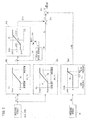
- the traveling body is provided with a variable displacement hydraulic motor 5 for traveling that is driven by a hydraulic circuit for traveling as shown in FIG. 1 .
- the discharged oil from a variable displacement type main pump 11, which is driven by an engine 10, is controlled by a control valve 12 for its direction and flow rate and is supplied to a variable displacement traveling motor 5 through a brake valve 14 having incorporated therein a counter balance valve 13.
- the rotation speed of the traveling motor 5 is changed through a transmission 7.
- the rotation after the change is transmitted to tires 6 through propeller shafts 8 and axles 9, so that the wheeled hydraulic excavator travels.
- the tilting amount of the main pump 11 is adjusted by a pump regulator 11A.
- the pump regulator is provided with a torque limiting unit, to which the pump discharge pressure is fedback to effect the control of horsepower.
- the horsepower control means a control of pump discharge pressure and displacement volume, so that the load that depends on both the pump discharge pressure and the pump displacement volume will not exceed the engine output.
- the regulator 11A is provided with a maximum tilting control unit, which determines the maximum flow rate of the main pump 11.
- the control valve 12 controls its switching direction and stroke amount for a traveling pilot pressure from the pilot circuit. By adjusting the stroke amount of the control valve 12, the flow rate and the pressure of the pressure oil supplied to the traveling motor 5 are adjusted, so that the traveling speed of the vehicle can be controlled.
- the pilot circuit includes a pilot pump 21, a pair of traveling pilot valves 23A, 23B that generate a pilot secondary pressure in response to pressing down on the traveling pedal 22, and a pair of slow-return valves 24A, 24B that are connected subsequent to the pilot valves 23A, 23B, respectively, and delay the pressure oil that is returnedtothe pilot valves 23A, 23B, respectively.
- the traveling pedal 22 can be rotated frontward and rearward by pressing down operation on the front side of the pedal (front pressing) and pressing down operation on the rear side of the pedal (rear pressing), respectively.
- the pilot valve 23A is actuated by the front pressing operation on the traveling pedal 22 and the pilot valve 23B is actuated by the rear pressing operation on the traveling pedal 22.
- pilot valves 23A, 23b pilot pressure depending on the operation amount of the traveling pedal 22 is generated.
- the traveling motor 5 includes a self-pressure tilting control mechanism, with which the displacement is increased to perform driving at low speed/high torque as the drive pressure increases whereas the displacement is decreased to perform driving at high speed/low torque as the drive pressure is decreased.
- the drive pressure acts on a control piston 17 and a servo piston 18 of the traveling motor 5 through a shuttle valve 16 in the brake valve 14.
- the pilot pressure from the pilot pump 21 acts on a corresponding pilot port of the control valve 12 when the traveling pedal 22 is pressed down on the front side or rear side of the traveling pedal 22, and the control valve 12 is switched to an F position or an R position depending on the pilot pressure.
- the discharged oil from the main pump 11 is conducted to the traveling motor 5 through the control valve 12, a center joint 15, and the brake valve 14.
- the delivered oil acts on the counter balance valve 13 as pilot pressure to switch the counter balance valve 13 from a neutral position.
- the traveling motor 5 is driven to allow the wheeled hydraulic excavator to travel.
- the traveling pilot pressures Pf, Pr that correspond to operations of pressing down on the traveling pedal 22 on its front and rear sides, respectively, are detected by pressure sensors 41A, 41B. Amounts of operation of the pedal are detected based on detected values of the pressure sensors 41A, 41B.
- the discharge pressure (traveling drive pressure) of the hydraulic pump 11 is detected by a pressure sensor 43.
- the output speed of the traveling motor 5 is detected by a vehicle speed sensor 42. Vehicle speed v, which depends on the output speed of the motor 5 and a reduction gear ratio of the transmission, is detected based on a detected value of the vehicle speed sensor 42. Signals from the sensors 41A, 41B, 42 and 43 are input into a controller 40, in which the engine rotation speed is controlled as described below.
- FIG. 2 is a block diagram illustrating the processing related to the control of the engine rotation speed in the controller 40.
- the controller 40 is configured as an arithmetic processing unit comprising a CPU, a ROM, a RAM, and other peripheral circuits.
- a function generator 501 stores characteristic f1 for a target rotation number Nt that corresponds to the traveling pilot pressures Pf, Pr (pedal operation amounts) as shown in FIG. 2 , in advance. According to the characteristic f1, the target rotation number Nt proportionally increases from a minimum rotation number Nmin to a maximum rotation number Nmax as the traveling pilot pressures Pf, Pr increase. The target rotation number Nt corresponding to the traveling pilot pressures Pf, Pr based on the characteristic f1 is output from the function generator 501.
- the function generator 502 stores a characteristic f2 for the target vehicle speed Va, which correspond to the traveling pilot pressures Pf, Pr (pedal operation amounts) as shown in FIG. 2 , in advance.
- the target vehicle speed va proportionally increases from 0 to a maximum vehicle speed vmax as the traveling pilot pressures Pf, Pr increase.
- the target vehicle speed va which corresponds to the traveling pilot pressures Pf, Pr based on the characteristic f2, is output from the function generator 502.
- the maximum vehicle speed vmax in FIG. 2 corresponds to the maximum vehicle speed vmax in the traveling performance diagram (see FIG. 7 ) when the traveling pedal 22 is fully operated.
- a function generator 503 stores a characteristic f3 of a correction rotation number ⁇ Na, which depends on the speed deviation ⁇ v as shown in FIG. 2 , in advance.
- the correction rotation number ⁇ Na is 0, when the speed deviation ⁇ v is 0, and the absolute value of the correction rotation number ⁇ Na increases as the absolute value of the speed deviation ⁇ v increases. That is, in a range where the speed deviation ⁇ v is equal to or greater than a predetermined value - ⁇ v1 and less than a predetermined value ⁇ v1 (- ⁇ v1 ⁇ ⁇ v ⁇ ⁇ v1), the correction rotation number ⁇ Na proportionally increases as the speed deviation ⁇ v increases.
- the correction rotation numbers ⁇ Na are limited to predetermined values - ⁇ N1 and + ⁇ N1, respectively.
- the correction rotation number ⁇ Na corresponding to the speed deviation ⁇ v is output based on the characteristic f3 from the function generator 503.
- a function generator 506 stores therein a characteristic f4 for a correction rotation number ⁇ Nb, which corresponds to the pump discharge pressure Pp as shown in FIG. 2 , in advance.
- a correction rotation number ⁇ Nb is 0 when the pump discharge pressure Pp is less than a predetermined value Pp1 (Pp ⁇ Pp1).
- the correction rotation number ⁇ Nb proportionally increases as the pump discharge pressure Pp increases in a range where the pump discharge pressure Pp is equal to or more than a predetermined value Pp1 and less than a predetermined value Pp2 (Pp1 ⁇ Pp ⁇ Pp2) .
- the correction rotation number ⁇ Nb is at maximum ⁇ N1 in a range where the pump discharge pressure Pp is equal to or more than a predetermined value Pp2 (Pp ⁇ Pp2).
- the controller 40 controls the rotation number so that the engine speed becomes a target rotation number N.
- a rotation number detector that detects an actual rotation number of the engine 10 is provided and a signal that depends on a deviation between the detected value and the target rotation number N is output to an engine rotation control unit such as an electronic governor to control the actual rotation number of the engine 10 to become the target rotation number N.
- the largest target rotation number Nx corresponds to an upper limit of the engine speed at which the engine 10 can operate normally.
- FIG. 3 is a timing chart illustrating the operations of the prime mover control device according to the present embodiment. It is assumed that in an initial state, the traveling pedal 22 is not operated, the vehicle speed v is 0, the engine rotation speed is a minimum rotation number Nmin, and the pump discharge pressure Pp is minimal. Starting from this state and when the traveling pedal 22 is maximally operated at a time point t1 in FIG. 3 , the control valve 12 is opened to supply the pressure oil from the hydraulic pump 11 to the traveling motor 5. As a result, the vehicle travels.
- the speed deviation ⁇ v is 0, through which the correction rotation number ⁇ N1 becomes 0, resulting in a decrease in the engine rotation speed to the maximum rotation number Nmax, while the maximum vehicle speed vmax is being maintained. Therefore, the vehicle speed v can be prevented from becoming higher than the maximum vehicle speed vmax.
- the vehicle can travel at the constant maximum vehicle speed vmax by compensating for the difference in performance by correcting the engine rotation speed in response to the vehicle speed, even if there are variations in the performances of devices such as the engine 10 and the hydraulic pump 11 due to the individual variability thereof. With this construction, the vehicle speed can be controlled to become the target vehicle speed va with high precision in response to the operation of the traveling pedal 22.
- FIG. 4 is a diagram illustrating changes of the engine rotation speed and vehicle speed v at time points t1 to t2 in greater detail.
- the correction rotation number ⁇ Na shaded area
- the correction rotation number ⁇ Na decreases gradually accompanying an increase in the vehicle speed v (i.e., a decrease in the speed deviation ⁇ v) and the engine rotation speed is limited to the maximum rotation number Nmax subsequent to the time point t2.
- the correction rotation number ⁇ Nb is added to the target rotation number Nt, so that the engine rotation speed is controlled to be at the maximum target rotation number Nx regardless of the vehicle speed v. Therefore, when a high load is applied to the vehicle, the engine of the vehicle can output high horsepower in response thereto, so that high load traveling can be performed with ease.
- High horsepower driving means the driving in which the maximum rotation speed of the engine 10 is increased if the traveling load increases to a predetermined value or higher in a state where the traveling pedal 22 is operated by a predetermined amount or more (for example, fully operated) and the maximum rotation number Nmax is output as the target rotation number Nt.
- the target rotation number N of the engine 1 upon full operation of the pedal is the maximum rotation number Nmax, for example, when the pump discharge pressure Pp is less than the predetermined value Pp1 as shown in FIG. 5 .
- the target rotation number N increases proportionally accompanying the increase in the pump discharge pressure Pp.
- the target rotation number N decreases proportionally as the pump discharge pressure Pp decreases, and when the pump discharge pressure Pp is below a predetermined value Pp1', the target rotation number N becomes the maximum rotation number Nmax.
- the characteristic of the target rotation number includes hysteresis, which is, however, not indispensable.
- FIG. 6 is a diagram illustrating PQ characteristic of the hydraulic pump 11.
- the PQ characteristic when the engine rotation speed assumes the maximum rotation number Nmax is represented by f10 and the PQ characteristic when the engine rotation speed is the largest target rotation number Nx is represented by f11.
- the target rotation number increases from Nmax to Nx in a range of the pump discharge pressure Pp between the predetermined values Pp1 and Pp2.
- the PQ characteristic is expressed by a curve connecting points a, b, c, d, and e in FIG. 6 . That is, the PQ characteristic is expressed by the characteristic f11 at high loads and by the characteristic f10 at low loads.
- the high horsepower driving can increase the pump discharge flow rate Q especially at high loads.
- the engine rotation speed is controlled to largest maximum target rotation number Nx regardless of traveling loads, if the actual vehicle speed v is lower than the target vehicle speed va by the predetermined value ⁇ v1 or more when the pedal has been maximally pressed down. Therefore, the PQ characteristic on this condition is expressed by a curve connecting the points a, b, c, and f in FIG. 6 , that is the characteristic f11, so that the pump flow rate Q can be increased not only at high loads but also at low loads. In particular, as compared with the high horsepower driving, the pump flow rate Q can be increased in the shaded area in FIG. 6 .
- FIG. 7 is a traveling performance diagram illustrating the relationship between the vehicle speed v and traction force.
- the characteristic f20 is the one when the engine rotation speed is at the maximum rotation number Nmax whereas a characteristic f21 is the one when the engine rotation speed is at the largest target rotation number Nx.
- the pump flow rate Q increases upon high load traveling in the high horsepower driving (see FIG. 6 )
- the traveling performance diagram in the high horsepower driving is expressed by the curve connecting the points a, b, c, d, and e in FIG. 7 .
- the engine rotation speed can be increased to the maximum target rotation number Nx in response to the speed deviation ⁇ v, so hat the traveling performance diagram is expressed by the characteristic f21, that is, by the curve connecting the points a, b, c, and f in FIG. 7 . Therefore, in the present embodiment, the vehicle speed v can be increased even in the low load area where the vehicle speed cannot be increased by the high horsepower driving (see the shaded area in FIG. 7 ), so that the vehicle speed v can be controlled to the maximum vehicle speed vmax regardless of the traveling loads.
- the correction rotation number ⁇ Nb in response to the traveling load is calculated based on the characteristic f4 of the function generator 506 and the calculated correction rotation number ⁇ Nb is added to the target rotation number Na in the adder 507.
- the characteristic f4 of the function generator 506 is not limited to this.
- a characteristic, in which the target rotation number is set to the maximum target rotation number Nx when the pump discharge pressure Pp assumes the predetermined value Pp2 or higher may be set to the function generator 506.
- a maximum value selection circuit may be provided instead of the adder 507 in order to control the engine rotation number to become the maximum target rotation number Nx regardless of the operation amount of the traveling pedal 22. This enables traveling suitable for high loads to be performed without maximally pressing down on the traveling pedal 22.
- the control of the engine rotation speed during traveling has been explained.
- the engine rotation speed when the engine rotation speed is to be controlled upon working, it may be constructed such that a characteristic f5 (broken line) of work engine rotation speed depending on the operation amount of the traveling pedal 22 is set in advance, for example, in the function generator 501 shown in FIG. 2 and the engine rotation speed is controlled based on the characteristic f5.
- a characteristic f5 broken line
- the engine rotation speed is controlled based on the characteristic f5.
- the processing in the adder 505 is passed on and the engine rotation number can be increased in the adder 507 upon high load working.
- the slope of the characteristic f5 upon working is made gentle and small in the maximum rotation number as compared with the characteristic f1 upon traveling.
- the shape of the characteristic f5 is not limited to this.
- the deviation ⁇ v between the target vehicle speed va which depends on the operation amount of the pedal, and the actual vehicle speed v, is calculated, and the correction amount ⁇ a of the engine rotation speed is made larger for the larger deviation ⁇ v.
- the configuration of the correction means is not limited to the above-mentioned ones.
- the target vehicle speed va corresponding to the operation amount of the pedal is calculated on the characteristic f1.
- the configuration of the vehicle speed calculation means is not limited thereto.
- the target rotation number Nt corresponding to the operation amount of the traveling pedal 22 is set in the function generator 501, and a signal depending on the deviation ⁇ v between the actual rotation speed and the target rotation number N of the engine 1 is output to an engine rotation speed control unit, thereby controlling the engine rotation speed to become the target rotation number N depending on the operation amount of the pedal.
- the configuration of the rotation number control means is not limited thereto.
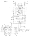
- an operation member 45 for setting a target rotation number may be separately provided as shown in FIG. 8 in order to set the target rotation number Nt depending on the operation amount of the operation member 45.
- the operation member 45 as the rotation number setting means may be constituted by a dial or the like. As shown in FIG.
- the target rotation number Nt may be output from the function generator 501 and the engine rotation speed can be controlled based on the correction rotation number ⁇ Na that depends on the target rotation number Nt and the speed deviation ⁇ v. That is, it may be configured that the flow rate supplied to the motor 5 can be controlled by switching the control valve 12 by the operation of the traveling pedal 22 while the target rotation number Nt is being kept constant, thus controlling the vehicle speed.
- the target rotation number that corresponds to the largest command value from the operation of the operation member 45 may be set to Nmax.
- a traveling command may be output by an operation member other than the traveling pedal 22.
- the flow of pressure oil from the hydraulic pump 11 to the hydraulic motor 5 is controlled by the control valve 12.
- the flow control means is not limited thereto.
- the flow control means may be configured as an HST circuit that includes the hydraulic pump 11 and the hydraulic motor 5 connected to each other so as to form a closed circuit in order to control the flow rate of the pressure oil discharged by the hydraulic pump 11 in response to the operation amount of the traveling pedal 22.
- the vehicle speed is detected by the vehicle speed sensor 42.
- the vehicle speed detection means may be of any type.
- the traveling load is detected by the pressure sensor 43.
- the load detection means may be of any type.
- the prime mover speed control device of the present invention is applied to a wheeled hydraulic excavator
- the present invention can also be applied to other hydraulically driven vehicles including a wheel loader and so on. That is, the present invention is not limited to the prime mover speed control device according to the embodiment of the present invention so far as the features and functions of the present invention can be realized therewith.
Landscapes
- Engineering & Computer Science (AREA)
- General Engineering & Computer Science (AREA)
- Combustion & Propulsion (AREA)
- Civil Engineering (AREA)
- Structural Engineering (AREA)
- Mechanical Engineering (AREA)
- Chemical & Material Sciences (AREA)
- Mining & Mineral Resources (AREA)
- Physics & Mathematics (AREA)
- Fluid Mechanics (AREA)
- Transportation (AREA)
- Control Of Vehicle Engines Or Engines For Specific Uses (AREA)
- Operation Control Of Excavators (AREA)
- Fluid-Pressure Circuits (AREA)
- Control Of Positive-Displacement Pumps (AREA)
Claims (3)
- Kraftmaschinen-Drehzahl-Steuerungssystem für ein hydraulisch angetriebenes Fahrzeug, umfassend:eine Hydraulikpumpe (11), die von einem Motor (10) angetrieben wird;einen Hydraulikmotor (5) zum Fahren, der mit Drucköl angetrieben wird, das von der Hydraulikpumpe geliefert wird, wobei die Drehung des Hydraulikmotors (5) über Antriebswellen (8) und Achsen (9) übertragen wird, wodurch ein Fahren des Fahrzeugs ermöglicht wird;ein Betätigungselement (22), das in Übereinstimmung mit einem Betätigungsgrad durch das Betätigungselement einen Fahrbefehl ausgibt;eine Strömungs-Steuerungsvorrichtung (12), die entweder eine Strömung des Drucköls von der Hydraulikpumpe zum Hydraulikmotor oder eine Strömungsrate des von der Hydraulikpumpe ausgestoßenen und an den Hydraulikmotor zum Fahren gelieferten Drucköls steuert, auf der Grundlage des Fahrbefehls, der in Übereinstimmung mit einem Betätigungsgrad durch das Betätigungselement ausgegeben wird; und dadurch gekennzeichnet, dass es ferner umfasst:eine Fahrzeuggeschwindigkeit-Erfassungsvorrichtung (42), die eine Fahrzeuggeschwindigkeit erfasst;eine Steuerungseinrichtung (40), die eine Zieldrehzahl des Motors steuert, wobei die Steuerungseinrichtung (40) umfasst:einen ersten Funktionsgenerator (501), der eine Zieldrehzahl Nt des Motors, die in einem Bereich zwischen einer minimalen Drehzahl und einer maximalen Drehzahl bestimmt wird, gemäß dem Betätigungsgrad des Betätigungselements (22) oder einem Betätigungsgrad einer Drehzahl-Einstellvorrichtung (45) auf der Grundlage einer Kennlinie einer Zieldrehzahl, die dem Betätigungsgrad des Betätigungselements oder dem Betätigungsgrad der Drehzahl-Einstellvorrichtung entspricht, ausgibt;einen zweiten Funktionsgenerator (502), der eine Zielfahrzeuggeschwindigkeit Va in einem Bereich zwischen 0 und einer maximalen Fahrzeuggeschwindigkeit berechnet, die in Übereinstimmung mit dem Betätigungsgrad durch das Betätigungselement (22) bestimmt wird auf der Grundlage einer Kennlinie der Zielfahrzeuggeschwindigkeit entsprechend dem Betätigungsgrad durch das Betätigungselement;einen Subtraktor (504), der durch Abziehen der erfassten Fahrzeuggeschwindigkeit von der Zielfahrzeuggeschwindigkeit Va eine Geschwindigkeitsabweichung Δv berechnet;einen dritten Funktionsgenerator (503), der eine KorrekturDrehzahl ΔNa auf der Grundlage der Geschwindigkeitsabweichung Δv und der Zielfahrzeuggeschwindigkeit Va unter der Verwendung einer Kennlinie f3 berechnet, wobei, wenn die Geschwindigkeitsabweichung Δv in einem Bereich ist, der größer oder gleich einem vorbestimmten Wert -Δv1 und kleiner als ein vorbestimmter Wert Δv1 ist, die Korrekturdrehzahl ΔNa proportional mit einer Zunahme der Geschwindigkeitsabweichung Δv größer wird, und wobei, wenn die Geschwindigkeitsabweichung Δv in einem Bereich ist, der kleiner als der vorbestimmte Wert -Δv1 und größer oder gleich dem vorbestimmten Wert Δv1 ist, die Korrekturdrehzahl ΔNa jeweils auf vorbestimmte Werte -ΔN1 bzw. +ΔN1 eingeschränkt ist;einen Addierer (505), der die Korrekturdrehzahl ΔNa zur Zieldrehzahl Nt addiert, um eine korrigierte Zieldrehzahl Na zu berechnen;wobei die korrigierte Zieldrehzahl Na größer als die von dem ersten Funktionsgenerator bestimmte Zieldrehzahl Nt ist, wenn die erfasste Fahrzeuggeschwindigkeit kleiner als die Zielfahrzeuggeschwindigkeit Va ist, und die korrigierte Zieldrehzahl Na kleiner als die von dem ersten Funktionsgenerator bestimmte Zieldrehzahl Nt ist, wenn die erfasste Fahrzeuggeschwindigkeit größer als die Zielfahrzeuggeschwindigkeit Va ist; undwobei, wenn gemäß einer maximalen Betätigung des Betätigungselements (22) oder der Drehzahl-Einstellvorrichtung (45) von dem ersten Funktionsgenerator (501) die maximale Drehzahl als die Zieldrehzahl ausgegeben wird, und die erfasste Fahrzeuggeschwindigkeit kleiner als die Zielfahrzeuggeschwindigkeit Va ist, der dritte Funktionsgenerator (503) einen Wert der Korrekturdrehzahl ΔNa ausgibt, der die Zieldrehzahl Nt auf einen Wert der korrigierten Zieldrehzahl Na einstellt, der größer als die maximale Drehzahl ist, wobei ein durch Addieren eines maximalen Werts ΔN1 der korrigierten Drehzahl ΔNa zur maximalen Drehzahl Nmax erhaltener Wert eine höchste Drehzahl Nx ist, die einer Obergrenze der Motordrehzahl entspricht, bei der der Motor normal betrieben werden kann.
- Kraftmaschinen-Drehzahl-Steuerungssystem für ein hydraulisch angetriebenes Fahrzeug gemäß Anspruch 1, ferner umfassend:eine Lasterfassungsvorrichtung (43), die durch Messen des Pumpausstoßdrucks PP eine Fahrlast des hydraulisch angetriebenen Fahrzeugs erfasst, und wobeidie Steuerungseinrichtung (40) ferner umfasst:einen vierten Funktionsgenerator (506), der entsprechend dem Pumpausstoßdruck PP unter der Verwendung einer Kennlinie f4 der Korrekturdrehzahl ΔNb in Abhängigkeit vom Pumpausstoßdruck PP eine Korrekturdrehzahl ΔNb berechnet, wobei ein Wert der Korrekturdrehzahl ΔNb gleich 0 ist, wenn der Pumpausstoßdruck PP kleiner als ein vorbestimmter Wert Pp1 ist, die Korrekturdrehzahl ΔNb proportional mit einer Zunahme des Pumpausstoßdrucks Pp in einem Bereich größer wird, in dem der Pumpausstoßdruck Pp größer oder gleich dem vorbestimmten Wert Pp1 und kleiner als ein vorbestimmter Wert Pp2 ist, und die Korrekturdrehzahl ΔNb bei einem maximalen Wert ΔN1 in einem Bereich ist, in dem der Pumpausstoßdruck Pp größer oder gleich dem vorbestimmten Wert Pp2 ist, und einen Addierer (507), der die Korrekturdrehzahl ΔNb zur korrigierten Zieldrehzahl Na addiert, und das Resultat wird als die letztendliche Zieldrehzahl N ausgegeben.
- Kraftmaschinen-Drehzahl-Steuerungssystem für ein hydraulisch angetriebenes Fahrzeug gemäß Anspruch 1, ferner umfassend:eine Lasterfassung (43), die eine Fahrlast des hydraulisch angetriebenen Fahrzeugs durch Messen des Pumpausstoßdrucks Pp erfasst, wobeidie Steuerungseinrichtung ferner umfasst:einen vierten Funktionsgenerator (506), der eine Kennlinie verwendet, die die Zieldrehzahl auf die maximale Drehzahl Nx setzt, wenn der Pumpausstoßdruck Pp einen vorbestimmten Wert Pp2 oder höher annimmt, und eine Maximalwert-Auswahlschaltung, die die Motordrehzahl unabhängig von dem Betätigungsgrad des Betätigungselements (22) auf die maximale Zieldrehzahl Nx steuert.
Applications Claiming Priority (2)
| Application Number | Priority Date | Filing Date | Title |
|---|---|---|---|
| JP2007049723A JP4871760B2 (ja) | 2007-02-28 | 2007-02-28 | 油圧駆動車両の原動機回転数制御装置 |
| PCT/JP2008/053530 WO2008105500A1 (ja) | 2007-02-28 | 2008-02-28 | 油圧駆動車両の原動機回転数制御装置 |
Publications (3)
| Publication Number | Publication Date |
|---|---|
| EP2131027A1 EP2131027A1 (de) | 2009-12-09 |
| EP2131027A4 EP2131027A4 (de) | 2012-10-17 |
| EP2131027B1 true EP2131027B1 (de) | 2015-05-06 |
Family
ID=39721324
Family Applications (1)
| Application Number | Title | Priority Date | Filing Date |
|---|---|---|---|
| EP20080712101 Active EP2131027B1 (de) | 2007-02-28 | 2008-02-28 | Kraftmaschinedrehzahlsteuervorrichtung für ein hydraulisch angetriebenes Fahrzeug |
Country Status (5)
| Country | Link |
|---|---|
| US (1) | US8494733B2 (de) |
| EP (1) | EP2131027B1 (de) |
| JP (1) | JP4871760B2 (de) |
| KR (1) | KR101390026B1 (de) |
| WO (1) | WO2008105500A1 (de) |
Families Citing this family (15)
| Publication number | Priority date | Publication date | Assignee | Title |
|---|---|---|---|---|
| JP5274581B2 (ja) * | 2008-12-17 | 2013-08-28 | 株式会社小松製作所 | 静油圧式変速車両の制御装置 |
| JP5222895B2 (ja) * | 2010-05-07 | 2013-06-26 | 株式会社小松製作所 | 作業車両及び作業車両の制御方法 |
| US8738250B2 (en) * | 2010-11-30 | 2014-05-27 | Caterpillar Inc. | Power source speed control in a machine with a CVT |
| WO2012091192A1 (ko) * | 2010-12-28 | 2012-07-05 | 볼보 컨스트럭션 이큅먼트 에이비 | 건설기계용 가변용량형 유압펌프 유량 제어방법 |
| JP5705755B2 (ja) | 2012-01-19 | 2015-04-22 | 日立建機株式会社 | 作業機械の油圧制御装置 |
| US9102372B2 (en) * | 2012-07-24 | 2015-08-11 | Caterpillar Inc. | Track drive system and method |
| US9772018B2 (en) | 2013-03-27 | 2017-09-26 | Kubota Corporation | Working machine |
| JP5913175B2 (ja) * | 2013-03-27 | 2016-04-27 | 株式会社クボタ | 作業機 |
| DE102014013252A1 (de) * | 2014-09-08 | 2016-03-10 | Hydac International Gmbh | Antriebseinrichtung für eine Güllepumpe |
| FR3026811B1 (fr) * | 2014-10-03 | 2016-12-09 | Poclain Hydraulics Ind | Procede d'assistance hydraulique de l'entrainement d'un vehicule a basse vitesse |
| JP6725356B2 (ja) * | 2016-07-29 | 2020-07-15 | Kyb株式会社 | 鉄道車両用制振装置 |
| KR102557830B1 (ko) * | 2017-01-02 | 2023-07-24 | 현대모비스 주식회사 | 전동식 동력 조향장치의 조향복원 제어장치 및 그 방법 |
| JP6872478B2 (ja) * | 2017-12-28 | 2021-05-19 | 日立建機株式会社 | ホイール式作業車両 |
| IT201900005150A1 (it) * | 2019-04-05 | 2020-10-05 | Cnh Ind Italia Spa | Trasmissione idrostatica per veicolo movimento terra con sistema per evitare sovravelocità del motore in fase di frenatura o di inversione del senso di marcia in discesa |
| US11669073B2 (en) | 2020-11-24 | 2023-06-06 | Caterpillar Trimble Control Technologies Llc | Velocity control for construction machines |
Family Cites Families (29)
| Publication number | Priority date | Publication date | Assignee | Title |
|---|---|---|---|---|
| JPH0263933A (ja) * | 1988-08-30 | 1990-03-05 | Honda Motor Co Ltd | 車両制御装置 |
| US5025685A (en) * | 1988-07-29 | 1991-06-25 | Honda Giken Kogyo Kabushiki Kaisha | Controlling device for non-stage transmission for vehicles |
| JP3048577B2 (ja) * | 1988-08-12 | 2000-06-05 | 本田技研工業株式会社 | 車両用無段変速機の制御装置 |
| JP2868592B2 (ja) | 1990-07-13 | 1999-03-10 | 日立建機株式会社 | 油圧駆動車両の原動機回転数制御装置 |
| JPH04143428A (ja) * | 1990-10-05 | 1992-05-18 | Komatsu Ltd | 建設機械の制御装置 |
| EP0553348B1 (de) * | 1990-10-16 | 1997-08-06 | Hitachi Construction Machinery Co., Ltd. | System zum regeln der motordrehzahl eines hydraulisch angetriebenen fahrzeuges |
| JP3155027B2 (ja) * | 1991-05-20 | 2001-04-09 | ジヤトコ・トランステクノロジー株式会社 | 自動変速機の変速制御装置 |
| AU660123B2 (en) | 1993-03-25 | 1995-06-08 | Matsushita Electric Industrial Co., Ltd. | Communication system |
| JP3800741B2 (ja) * | 1997-07-04 | 2006-07-26 | 日産自動車株式会社 | 無段変速機の足放しアップシフト変速制御装置 |
| US6371885B1 (en) * | 1999-04-01 | 2002-04-16 | Komatsu Ltd. | Working vehicle and vehicle speed control method thereof, variable power engine and power setting method thereof, and vehicle with variable power engine and power control method thereof |
| JP3757674B2 (ja) * | 1999-04-12 | 2006-03-22 | 日産自動車株式会社 | 車両の駆動力制御装置 |
| JP3815111B2 (ja) * | 1999-04-16 | 2006-08-30 | 日産自動車株式会社 | 車両の駆動力制御装置 |
| US6122588A (en) * | 1999-10-19 | 2000-09-19 | Ford Global Technologies, Inc. | Vehicle speed control with continuously variable braking torque |
| JP3539335B2 (ja) * | 2000-03-10 | 2004-07-07 | トヨタ自動車株式会社 | 無段変速機を備えた車両の制御装置 |
| JP4242038B2 (ja) * | 2000-04-14 | 2009-03-18 | 日立建機株式会社 | ホイール走行式油圧建設機械 |
| JP3578046B2 (ja) * | 2000-05-16 | 2004-10-20 | 日産自動車株式会社 | 車速制御装置 |
| KR100527824B1 (ko) * | 2000-09-08 | 2005-11-09 | 히다치 겡키 가부시키 가이샤 | 휠식 유압 주행 차량의 속도 제어 장치 |
| JP2002372148A (ja) * | 2001-06-14 | 2002-12-26 | Kayaba Ind Co Ltd | Hst車両の制御装置 |
| JP2003237421A (ja) * | 2002-02-18 | 2003-08-27 | Nissan Motor Co Ltd | 車両の駆動力制御装置 |
| JP3552710B2 (ja) * | 2002-09-04 | 2004-08-11 | 日産自動車株式会社 | 車両の駆動力制御装置 |
| WO2004029434A1 (ja) * | 2002-09-26 | 2004-04-08 | Hitachi Construction Machinery Co., Ltd. | 建設機械の原動機制御装置 |
| CN100410536C (zh) * | 2002-09-26 | 2008-08-13 | 日立建机株式会社 | 建筑机械的控制设备和计算输入力矩的方法 |
| US7096109B2 (en) * | 2002-11-12 | 2006-08-22 | Hitachi, Ltd. | Adaptive cruise control system |
| EP1420194B1 (de) * | 2002-11-13 | 2011-01-12 | Nissan Motor Company Limited | Schaltsteuerung für ein stufenloses Getriebe |
| JP4637748B2 (ja) * | 2003-10-22 | 2011-02-23 | 株式会社小松製作所 | 自走式リサイクル機の走行制御装置 |
| JP4272094B2 (ja) * | 2004-03-26 | 2009-06-03 | 株式会社小松製作所 | 作業車両の車速制御装置 |
| US8088036B2 (en) * | 2005-09-30 | 2012-01-03 | Jtekt Corporation | Drive control device for vehicle |
| JP4295308B2 (ja) * | 2006-12-04 | 2009-07-15 | 日立建機株式会社 | 作業車両の走行駆動装置 |
| US8322481B2 (en) * | 2006-12-28 | 2012-12-04 | Hitachi Construction Machinery Co., Ltd. | Traveling control apparatus for hydraulic traveling vehicle |
-
2007
- 2007-02-28 JP JP2007049723A patent/JP4871760B2/ja active Active
-
2008
- 2008-02-28 KR KR1020097017846A patent/KR101390026B1/ko active Active
- 2008-02-28 WO PCT/JP2008/053530 patent/WO2008105500A1/ja not_active Ceased
- 2008-02-28 EP EP20080712101 patent/EP2131027B1/de active Active
- 2008-02-28 US US12/529,162 patent/US8494733B2/en active Active
Also Published As
| Publication number | Publication date |
|---|---|
| US20100106382A1 (en) | 2010-04-29 |
| JP4871760B2 (ja) | 2012-02-08 |
| EP2131027A1 (de) | 2009-12-09 |
| US8494733B2 (en) | 2013-07-23 |
| JP2008215084A (ja) | 2008-09-18 |
| KR20090127126A (ko) | 2009-12-09 |
| WO2008105500A1 (ja) | 2008-09-04 |
| KR101390026B1 (ko) | 2014-04-29 |
| EP2131027A4 (de) | 2012-10-17 |
Similar Documents
| Publication | Publication Date | Title |
|---|---|---|
| EP2131027B1 (de) | Kraftmaschinedrehzahlsteuervorrichtung für ein hydraulisch angetriebenes Fahrzeug | |
| US5203168A (en) | Hydraulic driving circuit with motor displacement limitation control | |
| EP2131072B1 (de) | Fahrsteuervorrichtung für arbeitsfahrzeug | |
| JP5072926B2 (ja) | 作業車両 | |
| US20110308878A1 (en) | Construction vehicle | |
| EP3623665B1 (de) | Nutzfahrzeug und nutzfahrzeugsteuerungsverfahren | |
| EP3553348B1 (de) | Nutzfahrzeug und verfahren zur steuerung des nutzfahrzeugs | |
| EP3553297B1 (de) | Nutzfahrzeug und verfahren zur steuerung des nutzfahrzeugs | |
| WO2011027759A1 (ja) | 作業車両 | |
| EP1500850B1 (de) | Fahrsteuervorrichtung für hydraulisch angetriebenes fahrzeug, hydraulisch angetriebenes fahrzeug und hydraulischer bagger auf rädern | |
| JP5092061B1 (ja) | 作業車両及び作業車両の制御方法 | |
| EP3553347B1 (de) | Nutzfahrzeug und verfahren zur steuerung des nutzfahrzeugs | |
| WO2019163360A1 (ja) | 作業車両及び作業車両の制御方法 | |
| US11125327B2 (en) | Work vehicle and control method for work vehicle | |
| JP4121687B2 (ja) | 油圧走行車両 | |
| US10829909B2 (en) | Work vehicle and control method for work vehicle |
Legal Events
| Date | Code | Title | Description |
|---|---|---|---|
| PUAI | Public reference made under article 153(3) epc to a published international application that has entered the european phase |
Free format text: ORIGINAL CODE: 0009012 |
|
| 17P | Request for examination filed |
Effective date: 20090925 |
|
| AK | Designated contracting states |
Kind code of ref document: A1 Designated state(s): AT BE BG CH CY CZ DE DK EE ES FI FR GB GR HR HU IE IS IT LI LT LU LV MC MT NL NO PL PT RO SE SI SK TR |
|
| DAX | Request for extension of the european patent (deleted) | ||
| A4 | Supplementary search report drawn up and despatched |
Effective date: 20120919 |
|
| RIC1 | Information provided on ipc code assigned before grant |
Ipc: F02D 29/00 20060101ALI20120913BHEP Ipc: E02F 9/20 20060101ALI20120913BHEP Ipc: E02F 9/22 20060101ALI20120913BHEP Ipc: F02D 29/02 20060101AFI20120913BHEP |
|
| 17Q | First examination report despatched |
Effective date: 20130515 |
|
| GRAP | Despatch of communication of intention to grant a patent |
Free format text: ORIGINAL CODE: EPIDOSNIGR1 |
|
| RIC1 | Information provided on ipc code assigned before grant |
Ipc: B60W 10/06 20060101ALI20141106BHEP Ipc: E02F 9/20 20060101ALI20141106BHEP Ipc: F02D 29/02 20060101AFI20141106BHEP Ipc: F02D 29/00 20060101ALI20141106BHEP Ipc: F16H 59/68 20060101ALI20141106BHEP Ipc: F16H 61/431 20100101ALI20141106BHEP Ipc: F16H 61/423 20100101ALI20141106BHEP Ipc: E02F 9/22 20060101ALI20141106BHEP |
|
| INTG | Intention to grant announced |
Effective date: 20141125 |
|
| GRAP | Despatch of communication of intention to grant a patent |
Free format text: ORIGINAL CODE: EPIDOSNIGR1 |
|
| INTG | Intention to grant announced |
Effective date: 20150225 |
|
| GRAS | Grant fee paid |
Free format text: ORIGINAL CODE: EPIDOSNIGR3 |
|
| GRAA | (expected) grant |
Free format text: ORIGINAL CODE: 0009210 |
|
| AK | Designated contracting states |
Kind code of ref document: B1 Designated state(s): AT BE BG CH CY CZ DE DK EE ES FI FR GB GR HR HU IE IS IT LI LT LU LV MC MT NL NO PL PT RO SE SI SK TR |
|
| REG | Reference to a national code |
Ref country code: GB Ref legal event code: FG4D |
|
| REG | Reference to a national code |
Ref country code: CH Ref legal event code: EP |
|
| REG | Reference to a national code |
Ref country code: IE Ref legal event code: FG4D |
|
| REG | Reference to a national code |
Ref country code: AT Ref legal event code: REF Ref document number: 725884 Country of ref document: AT Kind code of ref document: T Effective date: 20150615 |
|
| REG | Reference to a national code |
Ref country code: DE Ref legal event code: R096 Ref document number: 602008038037 Country of ref document: DE Effective date: 20150618 |
|
| REG | Reference to a national code |
Ref country code: AT Ref legal event code: MK05 Ref document number: 725884 Country of ref document: AT Kind code of ref document: T Effective date: 20150506 |
|
| REG | Reference to a national code |
Ref country code: NL Ref legal event code: MP Effective date: 20150506 |
|
| REG | Reference to a national code |
Ref country code: LT Ref legal event code: MG4D |
|
| PG25 | Lapsed in a contracting state [announced via postgrant information from national office to epo] |
Ref country code: NO Free format text: LAPSE BECAUSE OF FAILURE TO SUBMIT A TRANSLATION OF THE DESCRIPTION OR TO PAY THE FEE WITHIN THE PRESCRIBED TIME-LIMIT Effective date: 20150806 Ref country code: ES Free format text: LAPSE BECAUSE OF FAILURE TO SUBMIT A TRANSLATION OF THE DESCRIPTION OR TO PAY THE FEE WITHIN THE PRESCRIBED TIME-LIMIT Effective date: 20150506 Ref country code: HR Free format text: LAPSE BECAUSE OF FAILURE TO SUBMIT A TRANSLATION OF THE DESCRIPTION OR TO PAY THE FEE WITHIN THE PRESCRIBED TIME-LIMIT Effective date: 20150506 Ref country code: PT Free format text: LAPSE BECAUSE OF FAILURE TO SUBMIT A TRANSLATION OF THE DESCRIPTION OR TO PAY THE FEE WITHIN THE PRESCRIBED TIME-LIMIT Effective date: 20150907 Ref country code: LT Free format text: LAPSE BECAUSE OF FAILURE TO SUBMIT A TRANSLATION OF THE DESCRIPTION OR TO PAY THE FEE WITHIN THE PRESCRIBED TIME-LIMIT Effective date: 20150506 Ref country code: FI Free format text: LAPSE BECAUSE OF FAILURE TO SUBMIT A TRANSLATION OF THE DESCRIPTION OR TO PAY THE FEE WITHIN THE PRESCRIBED TIME-LIMIT Effective date: 20150506 |
|
| PG25 | Lapsed in a contracting state [announced via postgrant information from national office to epo] |
Ref country code: IS Free format text: LAPSE BECAUSE OF FAILURE TO SUBMIT A TRANSLATION OF THE DESCRIPTION OR TO PAY THE FEE WITHIN THE PRESCRIBED TIME-LIMIT Effective date: 20150906 Ref country code: AT Free format text: LAPSE BECAUSE OF FAILURE TO SUBMIT A TRANSLATION OF THE DESCRIPTION OR TO PAY THE FEE WITHIN THE PRESCRIBED TIME-LIMIT Effective date: 20150506 Ref country code: GR Free format text: LAPSE BECAUSE OF FAILURE TO SUBMIT A TRANSLATION OF THE DESCRIPTION OR TO PAY THE FEE WITHIN THE PRESCRIBED TIME-LIMIT Effective date: 20150807 Ref country code: BG Free format text: LAPSE BECAUSE OF FAILURE TO SUBMIT A TRANSLATION OF THE DESCRIPTION OR TO PAY THE FEE WITHIN THE PRESCRIBED TIME-LIMIT Effective date: 20150806 Ref country code: LV Free format text: LAPSE BECAUSE OF FAILURE TO SUBMIT A TRANSLATION OF THE DESCRIPTION OR TO PAY THE FEE WITHIN THE PRESCRIBED TIME-LIMIT Effective date: 20150506 |
|
| REG | Reference to a national code |
Ref country code: FR Ref legal event code: PLFP Year of fee payment: 9 |
|
| PG25 | Lapsed in a contracting state [announced via postgrant information from national office to epo] |
Ref country code: EE Free format text: LAPSE BECAUSE OF FAILURE TO SUBMIT A TRANSLATION OF THE DESCRIPTION OR TO PAY THE FEE WITHIN THE PRESCRIBED TIME-LIMIT Effective date: 20150506 Ref country code: DK Free format text: LAPSE BECAUSE OF FAILURE TO SUBMIT A TRANSLATION OF THE DESCRIPTION OR TO PAY THE FEE WITHIN THE PRESCRIBED TIME-LIMIT Effective date: 20150506 |
|
| REG | Reference to a national code |
Ref country code: DE Ref legal event code: R097 Ref document number: 602008038037 Country of ref document: DE |
|
| PG25 | Lapsed in a contracting state [announced via postgrant information from national office to epo] |
Ref country code: SK Free format text: LAPSE BECAUSE OF FAILURE TO SUBMIT A TRANSLATION OF THE DESCRIPTION OR TO PAY THE FEE WITHIN THE PRESCRIBED TIME-LIMIT Effective date: 20150506 Ref country code: PL Free format text: LAPSE BECAUSE OF FAILURE TO SUBMIT A TRANSLATION OF THE DESCRIPTION OR TO PAY THE FEE WITHIN THE PRESCRIBED TIME-LIMIT Effective date: 20150506 Ref country code: CZ Free format text: LAPSE BECAUSE OF FAILURE TO SUBMIT A TRANSLATION OF THE DESCRIPTION OR TO PAY THE FEE WITHIN THE PRESCRIBED TIME-LIMIT Effective date: 20150506 Ref country code: RO Free format text: LAPSE BECAUSE OF NON-PAYMENT OF DUE FEES Effective date: 20150506 |
|
| PLBE | No opposition filed within time limit |
Free format text: ORIGINAL CODE: 0009261 |
|
| STAA | Information on the status of an ep patent application or granted ep patent |
Free format text: STATUS: NO OPPOSITION FILED WITHIN TIME LIMIT |
|
| 26N | No opposition filed |
Effective date: 20160209 |
|
| PG25 | Lapsed in a contracting state [announced via postgrant information from national office to epo] |
Ref country code: SI Free format text: LAPSE BECAUSE OF FAILURE TO SUBMIT A TRANSLATION OF THE DESCRIPTION OR TO PAY THE FEE WITHIN THE PRESCRIBED TIME-LIMIT Effective date: 20150506 Ref country code: BE Free format text: LAPSE BECAUSE OF NON-PAYMENT OF DUE FEES Effective date: 20160229 |
|
| PG25 | Lapsed in a contracting state [announced via postgrant information from national office to epo] |
Ref country code: BE Free format text: LAPSE BECAUSE OF FAILURE TO SUBMIT A TRANSLATION OF THE DESCRIPTION OR TO PAY THE FEE WITHIN THE PRESCRIBED TIME-LIMIT Effective date: 20150506 |
|
| PG25 | Lapsed in a contracting state [announced via postgrant information from national office to epo] |
Ref country code: LU Free format text: LAPSE BECAUSE OF FAILURE TO SUBMIT A TRANSLATION OF THE DESCRIPTION OR TO PAY THE FEE WITHIN THE PRESCRIBED TIME-LIMIT Effective date: 20160228 Ref country code: MC Free format text: LAPSE BECAUSE OF FAILURE TO SUBMIT A TRANSLATION OF THE DESCRIPTION OR TO PAY THE FEE WITHIN THE PRESCRIBED TIME-LIMIT Effective date: 20150506 |
|
| REG | Reference to a national code |
Ref country code: CH Ref legal event code: PL |
|
| PG25 | Lapsed in a contracting state [announced via postgrant information from national office to epo] |
Ref country code: LI Free format text: LAPSE BECAUSE OF NON-PAYMENT OF DUE FEES Effective date: 20160229 Ref country code: CH Free format text: LAPSE BECAUSE OF NON-PAYMENT OF DUE FEES Effective date: 20160229 |
|
| REG | Reference to a national code |
Ref country code: IE Ref legal event code: MM4A |
|
| REG | Reference to a national code |
Ref country code: FR Ref legal event code: PLFP Year of fee payment: 10 |
|
| PG25 | Lapsed in a contracting state [announced via postgrant information from national office to epo] |
Ref country code: IE Free format text: LAPSE BECAUSE OF NON-PAYMENT OF DUE FEES Effective date: 20160228 |
|
| PG25 | Lapsed in a contracting state [announced via postgrant information from national office to epo] |
Ref country code: NL Free format text: LAPSE BECAUSE OF FAILURE TO SUBMIT A TRANSLATION OF THE DESCRIPTION OR TO PAY THE FEE WITHIN THE PRESCRIBED TIME-LIMIT Effective date: 20150506 Ref country code: SE Free format text: LAPSE BECAUSE OF FAILURE TO SUBMIT A TRANSLATION OF THE DESCRIPTION OR TO PAY THE FEE WITHIN THE PRESCRIBED TIME-LIMIT Effective date: 20150506 |
|
| PG25 | Lapsed in a contracting state [announced via postgrant information from national office to epo] |
Ref country code: MT Free format text: LAPSE BECAUSE OF FAILURE TO SUBMIT A TRANSLATION OF THE DESCRIPTION OR TO PAY THE FEE WITHIN THE PRESCRIBED TIME-LIMIT Effective date: 20150506 |
|
| REG | Reference to a national code |
Ref country code: FR Ref legal event code: PLFP Year of fee payment: 11 |
|
| PG25 | Lapsed in a contracting state [announced via postgrant information from national office to epo] |
Ref country code: CY Free format text: LAPSE BECAUSE OF FAILURE TO SUBMIT A TRANSLATION OF THE DESCRIPTION OR TO PAY THE FEE WITHIN THE PRESCRIBED TIME-LIMIT Effective date: 20150506 Ref country code: HU Free format text: LAPSE BECAUSE OF FAILURE TO SUBMIT A TRANSLATION OF THE DESCRIPTION OR TO PAY THE FEE WITHIN THE PRESCRIBED TIME-LIMIT; INVALID AB INITIO Effective date: 20080228 |
|
| PG25 | Lapsed in a contracting state [announced via postgrant information from national office to epo] |
Ref country code: MT Free format text: LAPSE BECAUSE OF FAILURE TO SUBMIT A TRANSLATION OF THE DESCRIPTION OR TO PAY THE FEE WITHIN THE PRESCRIBED TIME-LIMIT Effective date: 20160229 Ref country code: TR Free format text: LAPSE BECAUSE OF FAILURE TO SUBMIT A TRANSLATION OF THE DESCRIPTION OR TO PAY THE FEE WITHIN THE PRESCRIBED TIME-LIMIT Effective date: 20150506 |
|
| PGFP | Annual fee paid to national office [announced via postgrant information from national office to epo] |
Ref country code: IT Payment date: 20230110 Year of fee payment: 16 |
|
| PG25 | Lapsed in a contracting state [announced via postgrant information from national office to epo] |
Ref country code: FR Free format text: LAPSE BECAUSE OF NON-PAYMENT OF DUE FEES Effective date: 20240229 |
|
| PG25 | Lapsed in a contracting state [announced via postgrant information from national office to epo] |
Ref country code: FR Free format text: LAPSE BECAUSE OF NON-PAYMENT OF DUE FEES Effective date: 20240229 |
|
| PG25 | Lapsed in a contracting state [announced via postgrant information from national office to epo] |
Ref country code: IT Free format text: LAPSE BECAUSE OF NON-PAYMENT OF DUE FEES Effective date: 20240228 |
|
| PGFP | Annual fee paid to national office [announced via postgrant information from national office to epo] |
Ref country code: FR Payment date: 20230110 Year of fee payment: 16 |
|
| PGFP | Annual fee paid to national office [announced via postgrant information from national office to epo] |
Ref country code: GB Payment date: 20260106 Year of fee payment: 19 |
|
| PGFP | Annual fee paid to national office [announced via postgrant information from national office to epo] |
Ref country code: DE Payment date: 20260102 Year of fee payment: 19 |