EP2131053A1 - Mehrteiliger Arretierstift - Google Patents
Mehrteiliger Arretierstift Download PDFInfo
- Publication number
- EP2131053A1 EP2131053A1 EP09161726A EP09161726A EP2131053A1 EP 2131053 A1 EP2131053 A1 EP 2131053A1 EP 09161726 A EP09161726 A EP 09161726A EP 09161726 A EP09161726 A EP 09161726A EP 2131053 A1 EP2131053 A1 EP 2131053A1
- Authority
- EP
- European Patent Office
- Prior art keywords
- piece
- pin
- nub
- housing
- bearing
- Prior art date
- Legal status (The legal status is an assumption and is not a legal conclusion. Google has not performed a legal analysis and makes no representation as to the accuracy of the status listed.)
- Granted
Links
- 238000000034 method Methods 0.000 claims abstract description 13
- 239000000463 material Substances 0.000 description 8
- 238000003780 insertion Methods 0.000 description 6
- 230000037431 insertion Effects 0.000 description 6
- 239000000314 lubricant Substances 0.000 description 5
- 230000007704 transition Effects 0.000 description 4
- 238000003820 Medium-pressure liquid chromatography Methods 0.000 description 2
- 238000010586 diagram Methods 0.000 description 2
- 230000000712 assembly Effects 0.000 description 1
- 238000000429 assembly Methods 0.000 description 1
- 230000006835 compression Effects 0.000 description 1
- 238000007906 compression Methods 0.000 description 1
- 238000010276 construction Methods 0.000 description 1
- 230000001934 delay Effects 0.000 description 1
- 238000007689 inspection Methods 0.000 description 1
- 238000004519 manufacturing process Methods 0.000 description 1
- 239000011800 void material Substances 0.000 description 1
- 239000002699 waste material Substances 0.000 description 1
Images




Classifications
-
- F—MECHANICAL ENGINEERING; LIGHTING; HEATING; WEAPONS; BLASTING
- F16—ENGINEERING ELEMENTS AND UNITS; GENERAL MEASURES FOR PRODUCING AND MAINTAINING EFFECTIVE FUNCTIONING OF MACHINES OR INSTALLATIONS; THERMAL INSULATION IN GENERAL
- F16C—SHAFTS; FLEXIBLE SHAFTS; ELEMENTS OR CRANKSHAFT MECHANISMS; ROTARY BODIES OTHER THAN GEARING ELEMENTS; BEARINGS
- F16C33/00—Parts of bearings; Special methods for making bearings or parts thereof
- F16C33/02—Parts of sliding-contact bearings
- F16C33/04—Brasses; Bushes; Linings
- F16C33/06—Sliding surface mainly made of metal
- F16C33/08—Attachment of brasses, bushes or linings to the bearing housing
-
- F—MECHANICAL ENGINEERING; LIGHTING; HEATING; WEAPONS; BLASTING
- F16—ENGINEERING ELEMENTS AND UNITS; GENERAL MEASURES FOR PRODUCING AND MAINTAINING EFFECTIVE FUNCTIONING OF MACHINES OR INSTALLATIONS; THERMAL INSULATION IN GENERAL
- F16B—DEVICES FOR FASTENING OR SECURING CONSTRUCTIONAL ELEMENTS OR MACHINE PARTS TOGETHER, e.g. NAILS, BOLTS, CIRCLIPS, CLAMPS, CLIPS OR WEDGES; JOINTS OR JOINTING
- F16B19/00—Bolts without screw-thread; Pins, including deformable elements; Rivets
- F16B19/02—Bolts or sleeves for positioning of machine parts, e.g. notched taper pins, fitting pins, sleeves, eccentric positioning rings
-
- F—MECHANICAL ENGINEERING; LIGHTING; HEATING; WEAPONS; BLASTING
- F16—ENGINEERING ELEMENTS AND UNITS; GENERAL MEASURES FOR PRODUCING AND MAINTAINING EFFECTIVE FUNCTIONING OF MACHINES OR INSTALLATIONS; THERMAL INSULATION IN GENERAL
- F16B—DEVICES FOR FASTENING OR SECURING CONSTRUCTIONAL ELEMENTS OR MACHINE PARTS TOGETHER, e.g. NAILS, BOLTS, CIRCLIPS, CLAMPS, CLIPS OR WEDGES; JOINTS OR JOINTING
- F16B35/00—Screw-bolts; Stay-bolts; Screw-threaded studs; Screws; Set screws
- F16B35/005—Set screws; Locking means therefor
-
- F—MECHANICAL ENGINEERING; LIGHTING; HEATING; WEAPONS; BLASTING
- F16—ENGINEERING ELEMENTS AND UNITS; GENERAL MEASURES FOR PRODUCING AND MAINTAINING EFFECTIVE FUNCTIONING OF MACHINES OR INSTALLATIONS; THERMAL INSULATION IN GENERAL
- F16C—SHAFTS; FLEXIBLE SHAFTS; ELEMENTS OR CRANKSHAFT MECHANISMS; ROTARY BODIES OTHER THAN GEARING ELEMENTS; BEARINGS
- F16C27/00—Elastic or yielding bearings or bearing supports, for exclusively rotary movement
- F16C27/02—Sliding-contact bearings
-
- F—MECHANICAL ENGINEERING; LIGHTING; HEATING; WEAPONS; BLASTING
- F16—ENGINEERING ELEMENTS AND UNITS; GENERAL MEASURES FOR PRODUCING AND MAINTAINING EFFECTIVE FUNCTIONING OF MACHINES OR INSTALLATIONS; THERMAL INSULATION IN GENERAL
- F16C—SHAFTS; FLEXIBLE SHAFTS; ELEMENTS OR CRANKSHAFT MECHANISMS; ROTARY BODIES OTHER THAN GEARING ELEMENTS; BEARINGS
- F16C35/00—Rigid support of bearing units; Housings, e.g. caps, covers
- F16C35/02—Rigid support of bearing units; Housings, e.g. caps, covers in the case of sliding-contact bearings
-
- F—MECHANICAL ENGINEERING; LIGHTING; HEATING; WEAPONS; BLASTING
- F04—POSITIVE - DISPLACEMENT MACHINES FOR LIQUIDS; PUMPS FOR LIQUIDS OR ELASTIC FLUIDS
- F04D—NON-POSITIVE-DISPLACEMENT PUMPS
- F04D29/00—Details, component parts, or accessories
- F04D29/04—Shafts or bearings, or assemblies thereof
- F04D29/046—Bearings
-
- F—MECHANICAL ENGINEERING; LIGHTING; HEATING; WEAPONS; BLASTING
- F04—POSITIVE - DISPLACEMENT MACHINES FOR LIQUIDS; PUMPS FOR LIQUIDS OR ELASTIC FLUIDS
- F04D—NON-POSITIVE-DISPLACEMENT PUMPS
- F04D29/00—Details, component parts, or accessories
- F04D29/05—Shafts or bearings, or assemblies thereof, specially adapted for elastic fluid pumps
- F04D29/056—Bearings
- F04D29/0563—Bearings cartridges
-
- F—MECHANICAL ENGINEERING; LIGHTING; HEATING; WEAPONS; BLASTING
- F16—ENGINEERING ELEMENTS AND UNITS; GENERAL MEASURES FOR PRODUCING AND MAINTAINING EFFECTIVE FUNCTIONING OF MACHINES OR INSTALLATIONS; THERMAL INSULATION IN GENERAL
- F16C—SHAFTS; FLEXIBLE SHAFTS; ELEMENTS OR CRANKSHAFT MECHANISMS; ROTARY BODIES OTHER THAN GEARING ELEMENTS; BEARINGS
- F16C17/00—Sliding-contact bearings for exclusively rotary movement
- F16C17/02—Sliding-contact bearings for exclusively rotary movement for radial load only
-
- F—MECHANICAL ENGINEERING; LIGHTING; HEATING; WEAPONS; BLASTING
- F16—ENGINEERING ELEMENTS AND UNITS; GENERAL MEASURES FOR PRODUCING AND MAINTAINING EFFECTIVE FUNCTIONING OF MACHINES OR INSTALLATIONS; THERMAL INSULATION IN GENERAL
- F16C—SHAFTS; FLEXIBLE SHAFTS; ELEMENTS OR CRANKSHAFT MECHANISMS; ROTARY BODIES OTHER THAN GEARING ELEMENTS; BEARINGS
- F16C17/00—Sliding-contact bearings for exclusively rotary movement
- F16C17/10—Sliding-contact bearings for exclusively rotary movement for both radial and axial load
-
- F—MECHANICAL ENGINEERING; LIGHTING; HEATING; WEAPONS; BLASTING
- F16—ENGINEERING ELEMENTS AND UNITS; GENERAL MEASURES FOR PRODUCING AND MAINTAINING EFFECTIVE FUNCTIONING OF MACHINES OR INSTALLATIONS; THERMAL INSULATION IN GENERAL
- F16C—SHAFTS; FLEXIBLE SHAFTS; ELEMENTS OR CRANKSHAFT MECHANISMS; ROTARY BODIES OTHER THAN GEARING ELEMENTS; BEARINGS
- F16C2226/00—Joining parts; Fastening; Assembling or mounting parts
- F16C2226/50—Positive connections
-
- F—MECHANICAL ENGINEERING; LIGHTING; HEATING; WEAPONS; BLASTING
- F16—ENGINEERING ELEMENTS AND UNITS; GENERAL MEASURES FOR PRODUCING AND MAINTAINING EFFECTIVE FUNCTIONING OF MACHINES OR INSTALLATIONS; THERMAL INSULATION IN GENERAL
- F16C—SHAFTS; FLEXIBLE SHAFTS; ELEMENTS OR CRANKSHAFT MECHANISMS; ROTARY BODIES OTHER THAN GEARING ELEMENTS; BEARINGS
- F16C2360/00—Engines or pumps
- F16C2360/23—Gas turbine engines
- F16C2360/24—Turbochargers
-
- F—MECHANICAL ENGINEERING; LIGHTING; HEATING; WEAPONS; BLASTING
- F16—ENGINEERING ELEMENTS AND UNITS; GENERAL MEASURES FOR PRODUCING AND MAINTAINING EFFECTIVE FUNCTIONING OF MACHINES OR INSTALLATIONS; THERMAL INSULATION IN GENERAL
- F16D—COUPLINGS FOR TRANSMITTING ROTATION; CLUTCHES; BRAKES
- F16D1/00—Couplings for rigidly connecting two coaxial shafts or other movable machine elements
- F16D1/10—Quick-acting couplings in which the parts are connected by simply bringing them together axially
- F16D2001/102—Quick-acting couplings in which the parts are connected by simply bringing them together axially the torque is transmitted via polygon shaped connections
-
- Y—GENERAL TAGGING OF NEW TECHNOLOGICAL DEVELOPMENTS; GENERAL TAGGING OF CROSS-SECTIONAL TECHNOLOGIES SPANNING OVER SEVERAL SECTIONS OF THE IPC; TECHNICAL SUBJECTS COVERED BY FORMER USPC CROSS-REFERENCE ART COLLECTIONS [XRACs] AND DIGESTS
- Y10—TECHNICAL SUBJECTS COVERED BY FORMER USPC
- Y10T—TECHNICAL SUBJECTS COVERED BY FORMER US CLASSIFICATION
- Y10T29/00—Metal working
- Y10T29/49—Method of mechanical manufacture
- Y10T29/49316—Impeller making
- Y10T29/4932—Turbomachine making
-
- Y—GENERAL TAGGING OF NEW TECHNOLOGICAL DEVELOPMENTS; GENERAL TAGGING OF CROSS-SECTIONAL TECHNOLOGIES SPANNING OVER SEVERAL SECTIONS OF THE IPC; TECHNICAL SUBJECTS COVERED BY FORMER USPC CROSS-REFERENCE ART COLLECTIONS [XRACs] AND DIGESTS
- Y10—TECHNICAL SUBJECTS COVERED BY FORMER USPC
- Y10T—TECHNICAL SUBJECTS COVERED BY FORMER US CLASSIFICATION
- Y10T29/00—Metal working
- Y10T29/49—Method of mechanical manufacture
- Y10T29/49826—Assembling or joining
-
- Y—GENERAL TAGGING OF NEW TECHNOLOGICAL DEVELOPMENTS; GENERAL TAGGING OF CROSS-SECTIONAL TECHNOLOGIES SPANNING OVER SEVERAL SECTIONS OF THE IPC; TECHNICAL SUBJECTS COVERED BY FORMER USPC CROSS-REFERENCE ART COLLECTIONS [XRACs] AND DIGESTS
- Y10—TECHNICAL SUBJECTS COVERED BY FORMER USPC
- Y10T—TECHNICAL SUBJECTS COVERED BY FORMER US CLASSIFICATION
- Y10T29/00—Metal working
- Y10T29/49—Method of mechanical manufacture
- Y10T29/49826—Assembling or joining
- Y10T29/49895—Associating parts by use of aligning means [e.g., use of a drift pin or a "fixture"]
-
- Y—GENERAL TAGGING OF NEW TECHNOLOGICAL DEVELOPMENTS; GENERAL TAGGING OF CROSS-SECTIONAL TECHNOLOGIES SPANNING OVER SEVERAL SECTIONS OF THE IPC; TECHNICAL SUBJECTS COVERED BY FORMER USPC CROSS-REFERENCE ART COLLECTIONS [XRACs] AND DIGESTS
- Y10—TECHNICAL SUBJECTS COVERED BY FORMER USPC
- Y10T—TECHNICAL SUBJECTS COVERED BY FORMER US CLASSIFICATION
- Y10T29/00—Metal working
- Y10T29/49—Method of mechanical manufacture
- Y10T29/49826—Assembling or joining
- Y10T29/49945—Assembling or joining by driven force fit
Definitions
- Some turbocharger assemblies include a so-called "Z bearing" to support a rotational shaft for a compressor wheel and turbine wheel.
- a bearing is typically located in a center housing of a turbocharger assembly by a unitary locating pin.
- the locating pin must be sufficiently durable.
- clearances associated with the locating pin should be chosen to prevent movements that could cause excessive wear over numerous operational cycles.
- the material of construction of the locating pin must be chosen to handle the forces over a lifetime of the turbocharger assembly.
- an exemplary multi-piece locating pin can address various issues associated with conventional unitary locating pins.
- Fig. 1 is a diagram of a conventional turbocharger assembly with a conventional unitary locating pin
- Fig. 2 is a side view and a cross-sectional view of an exemplary multi-piece locating pin
- Fig. 3 is an exploded cross-sectional view of the exemplary mutli-piece locating pin of Fig. 2 ;
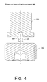
- Fig. 4 is an exploded cross-sectional view of an exemplary multi-piece locating pin with a broken nub
- Fig. 5 is a cross-sectional view of an exemplary multi-piece locating pin with a broken and captive nub
- Fig. 6 is a block diagram of an exemplary method.
- Fig. 1 shows a prior art assembly 100 for a turbocharger (e.g., a turbocharger assembly).
- the assembly 100 has a compressor side 104 and a turbine side 108 with a center housing 110 disposed between these two sides.
- the housing 110 includes a substantially cylindrical surface 112 that defines a bore.
- the surface 112 is typically disposed at a substantially constant radius about a central axis (e.g., which coincides with a rotational axis of the turbocharger).
- the bore defining surface 112 meets another surface 114 that extends less than 360° around the central axis and includes a radius that exceeds the bore radius so as to define a lubricant well for the bore.
- a bearing 120 is seated in the bore.
- the bearing 120 has a substantially cylindrical wall defined largely by an outer surface 121 and an inner surface 122.
- the outer surface 121 is disposed at an outer radius about a central axis of the bearing 120 and the inner surface 122 is disposed at an inner radius about the central axis.
- the radius of the outer surface 122 is less than the radius of the bore surface 112 and greater than the radius of the inner surface 122.
- the difference in the radii of the bore surface 112 and the outer surface 121 of the bearing define a lubricant film thickness that can help damp movement of the bearing 120 in the housing 110.
- An opening 122 in the wall of the bearing 120 allows lubricant to flow from the lubricant well defined by surface 114 to the inner surface 122 and correspondingly to a shaft bore defined by the inner surface 122.
- a shaft 140 is shown positioned in the shaft bore of the bearing 120.
- the shaft 140 has a compressor side journal surface 144 and a turbine side journal surface 148.
- the surfaces 144 and 148 are typically disposed at a common radius about a rotational axis of the shaft 140.
- the common radius of the journal surfaces 144 and 148 is less than the inner radius of 122 of the bearing 120.
- the difference in radii define a lubricant film thickness to lubricate the journal surfaces 144 and 148 as the shaft rotates in the bearing 120.
- axial movement e.g., translational movement
- rotational movement of the bearing 120 are limited by a locating pin mechanism.
- the locating pin mechanism relies on features of the housing 110, features of the bearing 120 and a locating pin 130.
- the housing 110 includes an opening 114 and threads 116 and a pilot surface 118.
- the bearing 120 includes an opening 128.
- the locating pin 130 includes a tool receptacle 132, threads 136 and a locating surface 138.
- These features of the housing 110, the bearing 120 and the pin 130 may be further defined by four regions R1, R2, R3 and R4 where R1 is referred to as a securing region, R2 is referred to as a transition region, R3 is referred to as a locating region and R4 is referred to as an excess region, which may or may not exist depending on dimensions of the various features.
- the housing 110 and the pin 130 include the securing region R1 and the transition region R2 while the bearing 120 and the pin 130 include the locating region R3.
- the locating surface 138 of the pin 130 is preferably aligned with the opening 128 of the bearing 120 to axially locate the bearing 120 in the bore of the housing 110 and to limit rotation of the bearing 120 about its axis.
- a tool may be positioned in the tool receptacle 132 of the pin 130 to rotate the pin 130 about a rotational axis. Accordingly, in the securing region R1, the threads 116 of the housing cooperate with the threads 136 of the locating pin 130 to secure the pin 130 in the housing 110.
- the pin 130 plays an important role in locating the bearing 120 in the housing 110.
- an assembly process may position the bearing 120 in the housing 110 along with the shaft 140, which, in turn is assembled with compressor and/or turbine components.
- the opening 128 of the bearing 120 and the opening defined by the pilot surface 118 of the housing 110 may not align.
- the axis of the opening 128 may be offset from the axis of the opening defined by the pilot surface 118.
- the pin 130 may cause the bearing 120 to shift in the bore of the housing 110.
- the pin 130 may not fit appropriately, which may require disassembly and reassembly of at least some components of the assembly 100.
- an improper fit may cause wear of the housing 110, the bearing 120 and/or the pin 130 when securing the pin 130 (e.g., due to rotation and translation of the pin 130).
- Such uncertainty as to fit or lack of appropriate fit can cause manufacturing delays and waste.
- an exemplary multi-piece locating pin can address such issues.
- Fig. 2 shows two views of an exemplary multi-piece locating pin 200 (a side view and a cross-sectional view along line A-A).
- the pin 200 includes a pin piece 220 and a screw piece 240.
- the pin piece 220 includes a locating surface 223 that acts to locate a bearing in a housing while the screw piece 240 includes a securing feature 242 that acts to secure the pin piece 220 in the housing.
- the pin piece 220 and the screw piece 240 cooperate via a receptacle 225 and a nub 245 arrangement.
- the screw piece 240 includes a nub 245 while the pin piece includes a receptacle 225 configured to receive the nub 245.
- the receptacle 225 and the nub 245 are substantially aligned on an axis of the multi-piece locating pin 200.
- the configuration of the receptacle 225 and the nub 245 may allow for rotation of nub 245 in the receptacle 225, for example, as the screw piece 240 is rotated. Such an optional arrangement allows the pin piece 220 to be inserted without any significant rotation of the pin piece 220.
- the nub 245 may have any of a variety of shapes.
- the nub 245 may be cylindrical.
- a nub may have a polygonal cross-section.
- the receptacle 225 may be a cylindrical void defined by a cylindrical surface. The depth of a receptacle is typically deeper than the length of a nub to allow for full insertion of the nub in the receptacle.
- a screw piece may have a receptacle and the pin piece a nub.
- the pin piece may be made of a more durable material than the screw piece, the arrangement of Fig. 2 is preferred.
- Another arrangement includes a screw piece with a receptacle and a pin piece with a receptacle and another piece that fits into both receptacles to allow for positioning or binding of the screw piece and the pin piece.
- the multi-piece locating pin 200 has an overall length L where the pin piece 220 has a length L-pin and a radius R-pin and where the screw piece 240 has a length L-screw and a radius R-screw.
- the pin piece 220 has a locating portion 222 adjacent a smaller radius waist portion 224 adjacent a shoulder portion 226 that abuts the screw piece 240.
- the screw piece 240 has threads or other securing feature 242 disposed between a head end 244 and a pin end 246.
- the head end 244 includes a tool receptacle 248 to receive a tool (e.g., a hex wrench, etc.).
- the screw piece 240 includes a securing region (R1) while the pin piece 220 includes a transition region (R2), a locating region (R3) and optionally an excess region (R4).
- the regions R1, R2, R3 and R4 Upon insertion of the MPLP 200 in a housing of a turbocharger assembly (see, e.g., the assembly 100 of Fig. 1 ), the regions R1, R2, R3 and R4 generally align with corresponding regions of the housing and bearing to thereby locate the bearing in the housing.
- Fig. 3 shows an exploded cross-sectional view of the exemplary MPLP 200 of Fig. 2 .
- the two pieces 220 and 240 may be joined at any time during an assembly process.
- the two pieces 220 and 240 may be provided as a unit where the nub 245 forms a compression fit with the receptacle 225 in a manner that allows the MPLC 200 to be handled without any significant risk of the pieces separating prior to insertion of the MPLC 200 into a housing to locate a bearing.
- Fig. 4 shows an exploded cross-sectional view of an exemplary MPLP 400 where the nub 245 has been detached from the screw piece 240.
- the nub 245 may be broken and detached from the screw piece 240.
- a worker may receive the MPLP 200 as a unit, separate the pieces 220 and 240 and then optionally break the nub 245.
- Fig. 5 shows a cross-sectional view of an exemplary MPLP 500 where the nub 245 has be broken, for example, cracked off or otherwise separated from the screw piece 240.
- the nub 245 may be broken yet held captive by the receptacle 225.
- Such an arrangement prevents the nub 245 from migrating.
- Such an arrangement can further hold nub debris captive and prevent such debris from migrating.
- a broken nub and/or associated debris can potentially cause damage to any of a variety of components of a turbocharger.
- a screw piece may be manufactured with a material of lesser "quality" than a corresponding pin piece.
- the pin piece must withstand axial forces and rotational forces exerted by a bearing.
- the pin piece must be made of a durable material.
- the screw piece is not subject to such forces, directly, it can be made of a less durable material.
- the screw piece may be made of a material that cost less than the material of the pin piece.
- the screw piece may be made of a material that is easier to machine or form.
- Fig. 6 shows an exemplary method 600 for securing a multi-piece locating pin in a housing to locate a bearing.
- the method 600 commences in a provision block 604 that includes providing pin and screw pieces, optionally as a unit.
- a position block 608 at least the pin piece is positioned in a locating opening of a bearing where the bearing is positioned in a bore of a housing.
- a decision block 612 a decision may be made as to whether the pin piece and the screw piece align. Such a decision may occur by default, for example, when securing the screw piece. Alternatively, such a decision may be made by a machine or a worker upon inspection.
- the decision block 612 decides that alignment does not exist, then, in a break block 616, the nub is broken and the method 600 continues in a secure block 620 to secure the screw piece and hence the pin piece. In some instances, the process of securing may cause a nub to break.
- alignment e.g., sufficient alignment
- an exemplary method may include providing a multi-piece locating pin; inserting a pin piece of the multi-piece locating pin into an opening in a wall of a bearing positioned in a bore of a housing of a turbocharger assembly; and securing a screw piece of the multi-piece locating pin in an opening of the housing to thereby secure the pin piece and axially locate the bearing in the bore of the housing of the turbocharger assembly.
- the screw piece may include a nub received by a receptacle of the pin piece. Further, the receptacle of the pin piece may receive a broken nub. A broken nub may indicate a misalignment of an axis of the pin piece and an axis of the screw piece.
- a pin piece and a screw piece may abut in the housing (see, e.g., the securing region R1 and the transition region R2).
Landscapes
- Engineering & Computer Science (AREA)
- General Engineering & Computer Science (AREA)
- Mechanical Engineering (AREA)
- Supercharger (AREA)
- Acyclic And Carbocyclic Compounds In Medicinal Compositions (AREA)
- Electrophonic Musical Instruments (AREA)
- Clamps And Clips (AREA)
Applications Claiming Priority (1)
| Application Number | Priority Date | Filing Date | Title |
|---|---|---|---|
| US12/132,123 US8186922B2 (en) | 2008-06-03 | 2008-06-03 | Multi-piece locating pin |
Publications (2)
| Publication Number | Publication Date |
|---|---|
| EP2131053A1 true EP2131053A1 (de) | 2009-12-09 |
| EP2131053B1 EP2131053B1 (de) | 2011-04-13 |
Family
ID=40821761
Family Applications (1)
| Application Number | Title | Priority Date | Filing Date |
|---|---|---|---|
| EP09161726A Active EP2131053B1 (de) | 2008-06-03 | 2009-06-02 | Mehrteiliger Arretierstift |
Country Status (4)
| Country | Link |
|---|---|
| US (2) | US8186922B2 (de) |
| EP (1) | EP2131053B1 (de) |
| AT (1) | ATE505660T1 (de) |
| DE (1) | DE602009001052D1 (de) |
Cited By (4)
| Publication number | Priority date | Publication date | Assignee | Title |
|---|---|---|---|---|
| US20120107112A1 (en) * | 2010-10-27 | 2012-05-03 | Precision Turbo & Engine Rebuilders, Inc. | Bearing retention assembly for and method of assembling turbochargers |
| EP3284964A1 (de) * | 2016-08-16 | 2018-02-21 | Bosch Mahle Turbo Systems GmbH & Co. KG | Lagereinrichtung eines abgasturboladers |
| US10228019B2 (en) | 2014-09-30 | 2019-03-12 | Ihi Corporation | Bearing structure and turbocharger |
| EP3511532A1 (de) * | 2018-01-15 | 2019-07-17 | Garrett Transportation I Inc. | Turbolader mit lagerbuchse und fixierstift |
Families Citing this family (10)
| Publication number | Priority date | Publication date | Assignee | Title |
|---|---|---|---|---|
| US9140185B2 (en) * | 2009-11-24 | 2015-09-22 | Honeywell International Inc. | Locating mechanism for turbocharger bearing |
| DE102011075517A1 (de) * | 2010-06-29 | 2011-12-29 | Bosch Mahle Turbo Systems Gmbh & Co. Kg | Lagergehäuse für eine Ladeeinrichtung |
| US9250150B1 (en) * | 2014-12-23 | 2016-02-02 | Honeywell International Inc. | Turbocharger wheel balance-test jig |
| DE102017218053B4 (de) | 2017-10-10 | 2019-06-19 | Continental Automotive Gmbh | Turboladereinrichtung und Verfahren zu deren Montage |
| DE102017219206A1 (de) * | 2017-10-26 | 2019-05-02 | BMTS Technology GmbH & Co. KG | Lagereinrichtung für einen Turbolader und Verfahrensvormontage einer Lagereinrichtung |
| DE102018126591A1 (de) | 2018-10-25 | 2020-04-30 | Ihi Charging Systems International Gmbh | Lagervorrichtung für einen Abgasturbolader und Abgasturbolader |
| CN109990994B (zh) * | 2019-04-04 | 2021-04-30 | 上海新松机器人有限公司 | 一种用于涡轮增压器检测的密封系统 |
| CN110332195B (zh) * | 2019-06-19 | 2024-03-12 | 长虹美菱股份有限公司 | 一种新型自攻螺钉加强固定扣结构 |
| CN111022465B (zh) * | 2019-12-29 | 2021-12-21 | 良匠(苏州)机械设备有限公司 | 一种高性能销轴及其加工方法 |
| DE102021111668A1 (de) | 2021-05-05 | 2022-11-10 | Ihi Charging Systems International Gmbh | Lagerabschnitt für einen Abgasturbolader und Abgasturbolader |
Citations (4)
| Publication number | Priority date | Publication date | Assignee | Title |
|---|---|---|---|---|
| DE1793166U (de) * | 1956-04-21 | 1959-08-06 | Philips Nv | Vorrichtung zur loesbaren befestigung eines teiles an einem anderen teil. |
| US5145334A (en) * | 1989-12-12 | 1992-09-08 | Allied-Signal Inc. | Turbocharger bearing retention and lubrication system |
| US5318375A (en) * | 1991-02-27 | 1994-06-07 | Jean Walterscheid Gmbh | Lock for securing a coupling sleeve |
| EP1705393A1 (de) | 2003-12-10 | 2006-09-27 | Jtekt Corporation | Lagervorrichtung für turbolader |
Family Cites Families (20)
| Publication number | Priority date | Publication date | Assignee | Title |
|---|---|---|---|---|
| US1394608A (en) * | 1920-04-29 | 1921-10-25 | Frederick E Buchser | Tool |
| US2993950A (en) * | 1959-06-17 | 1961-07-25 | Formar Ind Inc | Self-tapping non-conductive fastener |
| DE1793166A1 (de) | 1968-08-09 | 1970-12-10 | Hoechst Ag | Bisammoniumverbindungen und Verfahren zu ihrer Herstellung |
| US3747168A (en) * | 1971-11-08 | 1973-07-24 | Gen Motors Corp | Clamp assembly |
| US3817146A (en) * | 1972-10-24 | 1974-06-18 | W Scott | Bolt hole aligner and inserting tool |
| US4022099A (en) * | 1976-02-06 | 1977-05-10 | General Motors Corporation | Threaded fastener with reusable thread forming pilot tip |
| US4325665A (en) * | 1979-07-26 | 1982-04-20 | John A. Jukes | Threaded metal insert |
| US4798523A (en) * | 1986-12-19 | 1989-01-17 | Allied-Signal Inc. | Turbocharger bearing and lubrication system |
| US4858601A (en) * | 1988-05-27 | 1989-08-22 | Glisson Richard R | Adjustable compression bone screw |
| US5244323A (en) * | 1993-02-03 | 1993-09-14 | The United States Of America As Represented By The Secretary Of The Navy | Self locking set screw |
| US5681135A (en) * | 1995-01-19 | 1997-10-28 | Simonson; Peter Melott | Threaded fastener with multi-stage torque limiting applicator |
| US6116832A (en) * | 1996-08-20 | 2000-09-12 | Woco Franz-Josef Wolf & Co. | Screw with elastomer component to provide vibrational decoupling |
| JP3900599B2 (ja) * | 1997-06-30 | 2007-04-04 | 石川島播磨重工業株式会社 | ターボチャージャの軸受構造 |
| US6017184A (en) * | 1997-08-06 | 2000-01-25 | Allied Signal Inc. | Turbocharger integrated bearing system |
| US6439817B1 (en) * | 2001-03-19 | 2002-08-27 | Gary Jack Reed | Insert retention mechanism |
| GB2400154A (en) * | 2003-04-02 | 2004-10-06 | Autoliv Dev | Bolt having yieldable end cap for frictionally engaging threaded bores |
| US7425112B2 (en) * | 2003-04-29 | 2008-09-16 | Nowak Jr Edmund A | Tamper resistant screw |
| US7086705B2 (en) * | 2003-09-04 | 2006-08-08 | Benmaxx, Llc | Zinc stud insert |
| US7214037B2 (en) * | 2004-06-28 | 2007-05-08 | Honeywell International, Inc. | Retention of ball bearing cartridge for turbomachinery |
| US7588402B2 (en) * | 2006-08-31 | 2009-09-15 | Shu-Yun Chuang | Fastener with removable element |
-
2008
- 2008-06-03 US US12/132,123 patent/US8186922B2/en not_active Expired - Fee Related
-
2009
- 2009-06-02 DE DE602009001052T patent/DE602009001052D1/de active Active
- 2009-06-02 AT AT09161726T patent/ATE505660T1/de not_active IP Right Cessation
- 2009-06-02 EP EP09161726A patent/EP2131053B1/de active Active
-
2012
- 2012-05-24 US US13/479,688 patent/US9163668B2/en not_active Expired - Fee Related
Patent Citations (4)
| Publication number | Priority date | Publication date | Assignee | Title |
|---|---|---|---|---|
| DE1793166U (de) * | 1956-04-21 | 1959-08-06 | Philips Nv | Vorrichtung zur loesbaren befestigung eines teiles an einem anderen teil. |
| US5145334A (en) * | 1989-12-12 | 1992-09-08 | Allied-Signal Inc. | Turbocharger bearing retention and lubrication system |
| US5318375A (en) * | 1991-02-27 | 1994-06-07 | Jean Walterscheid Gmbh | Lock for securing a coupling sleeve |
| EP1705393A1 (de) | 2003-12-10 | 2006-09-27 | Jtekt Corporation | Lagervorrichtung für turbolader |
Cited By (6)
| Publication number | Priority date | Publication date | Assignee | Title |
|---|---|---|---|---|
| US20120107112A1 (en) * | 2010-10-27 | 2012-05-03 | Precision Turbo & Engine Rebuilders, Inc. | Bearing retention assembly for and method of assembling turbochargers |
| US8449199B2 (en) * | 2010-10-27 | 2013-05-28 | Precision Turbo & Engine Rebuilders, Inc. | Bearing retention assembly for and method of assembling turbochargers |
| US10228019B2 (en) | 2014-09-30 | 2019-03-12 | Ihi Corporation | Bearing structure and turbocharger |
| EP3284964A1 (de) * | 2016-08-16 | 2018-02-21 | Bosch Mahle Turbo Systems GmbH & Co. KG | Lagereinrichtung eines abgasturboladers |
| EP3511532A1 (de) * | 2018-01-15 | 2019-07-17 | Garrett Transportation I Inc. | Turbolader mit lagerbuchse und fixierstift |
| US11486268B2 (en) | 2018-01-15 | 2022-11-01 | Garrett Transportation I Inc. | Turbocharger assembly |
Also Published As
| Publication number | Publication date |
|---|---|
| US8186922B2 (en) | 2012-05-29 |
| US20090293257A1 (en) | 2009-12-03 |
| US9163668B2 (en) | 2015-10-20 |
| US20120246905A1 (en) | 2012-10-04 |
| EP2131053B1 (de) | 2011-04-13 |
| DE602009001052D1 (de) | 2011-05-26 |
| ATE505660T1 (de) | 2011-04-15 |
Similar Documents
| Publication | Publication Date | Title |
|---|---|---|
| US8186922B2 (en) | Multi-piece locating pin | |
| EP2325457B1 (de) | Auffindungsmechanismus für ein Turboladerlager | |
| US7980604B2 (en) | Bearing puller | |
| IL203097A (en) | Quick link for milling with interchangeable head | |
| US8251590B2 (en) | Anti-rotation bearing assembly and bearing | |
| JP5880706B2 (ja) | ターボ機械 | |
| US8256082B2 (en) | Multi-part pin remover for removing a pin or stud from a hole of a component | |
| US20040261269A1 (en) | Shaft and hub mounting system and method | |
| JP6889113B2 (ja) | コレットチャック | |
| US20130114996A1 (en) | Serviceable Spherical Joints with Wear-Compensation Features | |
| CA2636422C (en) | Quick-change bearing assembly that obviates the need to recenter replacement spindles | |
| EP2461054B1 (de) | Lagervorrichtung | |
| US8635779B2 (en) | Method of servicing a coupling connecting two non-collinear shafts | |
| US9687974B2 (en) | Oversize bearing retrofit using internal wire lock and installation tool/method for installation | |
| CN110998076B (zh) | 异物去除装置以及具有该异物去除装置的涡轮增压器 | |
| US20160076576A1 (en) | Disposable aligner for self-tapping threaded insert | |
| CN105579173A (zh) | 用于金属加工的可换头部系统 | |
| JP2001173669A (ja) | 軸受装置 | |
| JP2681876B2 (ja) | ユニバーサルジョイントの製造方法 | |
| CN221665122U (zh) | 一种轴承座 | |
| US20070022594A1 (en) | Device and method for releasing a rivet connection | |
| JP2008254126A (ja) | コンロッド組付け用工具 | |
| JP4831567B2 (ja) | スクリュー部品及びスクリューコンベア | |
| CN121399388A (zh) | 分体式滚动元件轴承保持架 | |
| CN117082968A (zh) | 用于农业机械或割草机械的滚筒以及包括该滚筒的农业机械或割草机械 |
Legal Events
| Date | Code | Title | Description |
|---|---|---|---|
| PUAI | Public reference made under article 153(3) epc to a published international application that has entered the european phase |
Free format text: ORIGINAL CODE: 0009012 |
|
| 17P | Request for examination filed |
Effective date: 20090602 |
|
| AK | Designated contracting states |
Kind code of ref document: A1 Designated state(s): AT BE BG CH CY CZ DE DK EE ES FI FR GB GR HR HU IE IS IT LI LT LU LV MC MK MT NL NO PL PT RO SE SI SK TR |
|
| 17Q | First examination report despatched |
Effective date: 20091201 |
|
| GRAP | Despatch of communication of intention to grant a patent |
Free format text: ORIGINAL CODE: EPIDOSNIGR1 |
|
| RIC1 | Information provided on ipc code assigned before grant |
Ipc: F01D 25/16 20060101ALI20101129BHEP Ipc: F16B 7/04 20060101ALI20101129BHEP Ipc: F16D 1/08 20060101ALI20101129BHEP Ipc: F16B 21/12 20060101ALI20101129BHEP Ipc: F16C 33/08 20060101AFI20101129BHEP Ipc: F16C 35/02 20060101ALI20101129BHEP |
|
| GRAS | Grant fee paid |
Free format text: ORIGINAL CODE: EPIDOSNIGR3 |
|
| GRAA | (expected) grant |
Free format text: ORIGINAL CODE: 0009210 |
|
| AK | Designated contracting states |
Kind code of ref document: B1 Designated state(s): AT BE BG CH CY CZ DE DK EE ES FI FR GB GR HR HU IE IS IT LI LT LU LV MC MK MT NL NO PL PT RO SE SI SK TR |
|
| REG | Reference to a national code |
Ref country code: GB Ref legal event code: FG4D |
|
| REG | Reference to a national code |
Ref country code: CH Ref legal event code: EP |
|
| REG | Reference to a national code |
Ref country code: IE Ref legal event code: FG4D |
|
| REF | Corresponds to: |
Ref document number: 602009001052 Country of ref document: DE Date of ref document: 20110526 Kind code of ref document: P |
|
| REG | Reference to a national code |
Ref country code: DE Ref legal event code: R096 Ref document number: 602009001052 Country of ref document: DE Effective date: 20110526 |
|
| REG | Reference to a national code |
Ref country code: NL Ref legal event code: VDEP Effective date: 20110413 |
|
| LTIE | Lt: invalidation of european patent or patent extension |
Effective date: 20110413 |
|
| PG25 | Lapsed in a contracting state [announced via postgrant information from national office to epo] |
Ref country code: NO Free format text: LAPSE BECAUSE OF FAILURE TO SUBMIT A TRANSLATION OF THE DESCRIPTION OR TO PAY THE FEE WITHIN THE PRESCRIBED TIME-LIMIT Effective date: 20110713 Ref country code: HR Free format text: LAPSE BECAUSE OF FAILURE TO SUBMIT A TRANSLATION OF THE DESCRIPTION OR TO PAY THE FEE WITHIN THE PRESCRIBED TIME-LIMIT Effective date: 20110413 Ref country code: SE Free format text: LAPSE BECAUSE OF FAILURE TO SUBMIT A TRANSLATION OF THE DESCRIPTION OR TO PAY THE FEE WITHIN THE PRESCRIBED TIME-LIMIT Effective date: 20110413 Ref country code: PT Free format text: LAPSE BECAUSE OF FAILURE TO SUBMIT A TRANSLATION OF THE DESCRIPTION OR TO PAY THE FEE WITHIN THE PRESCRIBED TIME-LIMIT Effective date: 20110816 Ref country code: LT Free format text: LAPSE BECAUSE OF FAILURE TO SUBMIT A TRANSLATION OF THE DESCRIPTION OR TO PAY THE FEE WITHIN THE PRESCRIBED TIME-LIMIT Effective date: 20110413 |
|
| PG25 | Lapsed in a contracting state [announced via postgrant information from national office to epo] |
Ref country code: IS Free format text: LAPSE BECAUSE OF FAILURE TO SUBMIT A TRANSLATION OF THE DESCRIPTION OR TO PAY THE FEE WITHIN THE PRESCRIBED TIME-LIMIT Effective date: 20110813 Ref country code: FI Free format text: LAPSE BECAUSE OF FAILURE TO SUBMIT A TRANSLATION OF THE DESCRIPTION OR TO PAY THE FEE WITHIN THE PRESCRIBED TIME-LIMIT Effective date: 20110413 Ref country code: CY Free format text: LAPSE BECAUSE OF FAILURE TO SUBMIT A TRANSLATION OF THE DESCRIPTION OR TO PAY THE FEE WITHIN THE PRESCRIBED TIME-LIMIT Effective date: 20110413 Ref country code: BE Free format text: LAPSE BECAUSE OF FAILURE TO SUBMIT A TRANSLATION OF THE DESCRIPTION OR TO PAY THE FEE WITHIN THE PRESCRIBED TIME-LIMIT Effective date: 20110413 Ref country code: SI Free format text: LAPSE BECAUSE OF FAILURE TO SUBMIT A TRANSLATION OF THE DESCRIPTION OR TO PAY THE FEE WITHIN THE PRESCRIBED TIME-LIMIT Effective date: 20110413 Ref country code: ES Free format text: LAPSE BECAUSE OF FAILURE TO SUBMIT A TRANSLATION OF THE DESCRIPTION OR TO PAY THE FEE WITHIN THE PRESCRIBED TIME-LIMIT Effective date: 20110724 Ref country code: AT Free format text: LAPSE BECAUSE OF FAILURE TO SUBMIT A TRANSLATION OF THE DESCRIPTION OR TO PAY THE FEE WITHIN THE PRESCRIBED TIME-LIMIT Effective date: 20110413 Ref country code: GR Free format text: LAPSE BECAUSE OF FAILURE TO SUBMIT A TRANSLATION OF THE DESCRIPTION OR TO PAY THE FEE WITHIN THE PRESCRIBED TIME-LIMIT Effective date: 20110714 Ref country code: LV Free format text: LAPSE BECAUSE OF FAILURE TO SUBMIT A TRANSLATION OF THE DESCRIPTION OR TO PAY THE FEE WITHIN THE PRESCRIBED TIME-LIMIT Effective date: 20110413 |
|
| PG25 | Lapsed in a contracting state [announced via postgrant information from national office to epo] |
Ref country code: NL Free format text: LAPSE BECAUSE OF FAILURE TO SUBMIT A TRANSLATION OF THE DESCRIPTION OR TO PAY THE FEE WITHIN THE PRESCRIBED TIME-LIMIT Effective date: 20110413 Ref country code: MT Free format text: LAPSE BECAUSE OF FAILURE TO SUBMIT A TRANSLATION OF THE DESCRIPTION OR TO PAY THE FEE WITHIN THE PRESCRIBED TIME-LIMIT Effective date: 20110413 |
|
| PG25 | Lapsed in a contracting state [announced via postgrant information from national office to epo] |
Ref country code: CZ Free format text: LAPSE BECAUSE OF FAILURE TO SUBMIT A TRANSLATION OF THE DESCRIPTION OR TO PAY THE FEE WITHIN THE PRESCRIBED TIME-LIMIT Effective date: 20110413 Ref country code: EE Free format text: LAPSE BECAUSE OF FAILURE TO SUBMIT A TRANSLATION OF THE DESCRIPTION OR TO PAY THE FEE WITHIN THE PRESCRIBED TIME-LIMIT Effective date: 20110413 |
|
| PLBE | No opposition filed within time limit |
Free format text: ORIGINAL CODE: 0009261 |
|
| STAA | Information on the status of an ep patent application or granted ep patent |
Free format text: STATUS: NO OPPOSITION FILED WITHIN TIME LIMIT |
|
| PG25 | Lapsed in a contracting state [announced via postgrant information from national office to epo] |
Ref country code: SK Free format text: LAPSE BECAUSE OF FAILURE TO SUBMIT A TRANSLATION OF THE DESCRIPTION OR TO PAY THE FEE WITHIN THE PRESCRIBED TIME-LIMIT Effective date: 20110413 Ref country code: PL Free format text: LAPSE BECAUSE OF FAILURE TO SUBMIT A TRANSLATION OF THE DESCRIPTION OR TO PAY THE FEE WITHIN THE PRESCRIBED TIME-LIMIT Effective date: 20110413 |
|
| 26N | No opposition filed |
Effective date: 20120116 |
|
| REG | Reference to a national code |
Ref country code: IE Ref legal event code: MM4A |
|
| PG25 | Lapsed in a contracting state [announced via postgrant information from national office to epo] |
Ref country code: IE Free format text: LAPSE BECAUSE OF NON-PAYMENT OF DUE FEES Effective date: 20110602 |
|
| REG | Reference to a national code |
Ref country code: DE Ref legal event code: R097 Ref document number: 602009001052 Country of ref document: DE Effective date: 20120116 |
|
| PG25 | Lapsed in a contracting state [announced via postgrant information from national office to epo] |
Ref country code: IT Free format text: LAPSE BECAUSE OF FAILURE TO SUBMIT A TRANSLATION OF THE DESCRIPTION OR TO PAY THE FEE WITHIN THE PRESCRIBED TIME-LIMIT Effective date: 20110413 |
|
| PG25 | Lapsed in a contracting state [announced via postgrant information from national office to epo] |
Ref country code: MK Free format text: LAPSE BECAUSE OF FAILURE TO SUBMIT A TRANSLATION OF THE DESCRIPTION OR TO PAY THE FEE WITHIN THE PRESCRIBED TIME-LIMIT Effective date: 20110413 |
|
| PG25 | Lapsed in a contracting state [announced via postgrant information from national office to epo] |
Ref country code: MC Free format text: LAPSE BECAUSE OF NON-PAYMENT OF DUE FEES Effective date: 20110630 |
|
| PG25 | Lapsed in a contracting state [announced via postgrant information from national office to epo] |
Ref country code: LU Free format text: LAPSE BECAUSE OF NON-PAYMENT OF DUE FEES Effective date: 20110602 |
|
| PG25 | Lapsed in a contracting state [announced via postgrant information from national office to epo] |
Ref country code: BG Free format text: LAPSE BECAUSE OF FAILURE TO SUBMIT A TRANSLATION OF THE DESCRIPTION OR TO PAY THE FEE WITHIN THE PRESCRIBED TIME-LIMIT Effective date: 20110713 |
|
| PG25 | Lapsed in a contracting state [announced via postgrant information from national office to epo] |
Ref country code: TR Free format text: LAPSE BECAUSE OF FAILURE TO SUBMIT A TRANSLATION OF THE DESCRIPTION OR TO PAY THE FEE WITHIN THE PRESCRIBED TIME-LIMIT Effective date: 20110413 |
|
| PG25 | Lapsed in a contracting state [announced via postgrant information from national office to epo] |
Ref country code: HU Free format text: LAPSE BECAUSE OF FAILURE TO SUBMIT A TRANSLATION OF THE DESCRIPTION OR TO PAY THE FEE WITHIN THE PRESCRIBED TIME-LIMIT Effective date: 20110413 |
|
| REG | Reference to a national code |
Ref country code: CH Ref legal event code: PL |
|
| PG25 | Lapsed in a contracting state [announced via postgrant information from national office to epo] |
Ref country code: LI Free format text: LAPSE BECAUSE OF NON-PAYMENT OF DUE FEES Effective date: 20130630 Ref country code: CH Free format text: LAPSE BECAUSE OF NON-PAYMENT OF DUE FEES Effective date: 20130630 |
|
| REG | Reference to a national code |
Ref country code: FR Ref legal event code: PLFP Year of fee payment: 7 |
|
| PGFP | Annual fee paid to national office [announced via postgrant information from national office to epo] |
Ref country code: GB Payment date: 20150526 Year of fee payment: 7 |
|
| PGFP | Annual fee paid to national office [announced via postgrant information from national office to epo] |
Ref country code: FR Payment date: 20150528 Year of fee payment: 7 |
|
| PGFP | Annual fee paid to national office [announced via postgrant information from national office to epo] |
Ref country code: DE Payment date: 20150630 Year of fee payment: 7 |
|
| REG | Reference to a national code |
Ref country code: DE Ref legal event code: R119 Ref document number: 602009001052 Country of ref document: DE |
|
| GBPC | Gb: european patent ceased through non-payment of renewal fee |
Effective date: 20160602 |
|
| REG | Reference to a national code |
Ref country code: FR Ref legal event code: ST Effective date: 20170228 |
|
| PG25 | Lapsed in a contracting state [announced via postgrant information from national office to epo] |
Ref country code: FR Free format text: LAPSE BECAUSE OF NON-PAYMENT OF DUE FEES Effective date: 20160630 Ref country code: DE Free format text: LAPSE BECAUSE OF NON-PAYMENT OF DUE FEES Effective date: 20170103 |
|
| PG25 | Lapsed in a contracting state [announced via postgrant information from national office to epo] |
Ref country code: GB Free format text: LAPSE BECAUSE OF NON-PAYMENT OF DUE FEES Effective date: 20160602 |