EP2131114B1 - Tube ondulé en plastique doté d'une section transversale aplatie - Google Patents
Tube ondulé en plastique doté d'une section transversale aplatie Download PDFInfo
- Publication number
- EP2131114B1 EP2131114B1 EP09156181A EP09156181A EP2131114B1 EP 2131114 B1 EP2131114 B1 EP 2131114B1 EP 09156181 A EP09156181 A EP 09156181A EP 09156181 A EP09156181 A EP 09156181A EP 2131114 B1 EP2131114 B1 EP 2131114B1
- Authority
- EP
- European Patent Office
- Prior art keywords
- side walls
- curvature
- top wall
- height dimension
- internal
- Prior art date
- Legal status (The legal status is an assumption and is not a legal conclusion. Google has not performed a legal analysis and makes no representation as to the accuracy of the status listed.)
- Active
Links
Images


Classifications
-
- F—MECHANICAL ENGINEERING; LIGHTING; HEATING; WEAPONS; BLASTING
- F24—HEATING; RANGES; VENTILATING
- F24F—AIR-CONDITIONING; AIR-HUMIDIFICATION; VENTILATION; USE OF AIR CURRENTS FOR SCREENING
- F24F13/00—Details common to, or for air-conditioning, air-humidification, ventilation or use of air currents for screening
- F24F13/02—Ducting arrangements
- F24F13/0218—Flexible soft ducts, e.g. ducts made of permeable textiles
-
- F—MECHANICAL ENGINEERING; LIGHTING; HEATING; WEAPONS; BLASTING
- F16—ENGINEERING ELEMENTS AND UNITS; GENERAL MEASURES FOR PRODUCING AND MAINTAINING EFFECTIVE FUNCTIONING OF MACHINES OR INSTALLATIONS; THERMAL INSULATION IN GENERAL
- F16L—PIPES; JOINTS OR FITTINGS FOR PIPES; SUPPORTS FOR PIPES, CABLES OR PROTECTIVE TUBING; MEANS FOR THERMAL INSULATION IN GENERAL
- F16L11/00—Hoses, i.e. flexible pipes
- F16L11/04—Hoses, i.e. flexible pipes made of rubber or flexible plastics
- F16L11/11—Hoses, i.e. flexible pipes made of rubber or flexible plastics with corrugated wall
-
- F—MECHANICAL ENGINEERING; LIGHTING; HEATING; WEAPONS; BLASTING
- F16—ENGINEERING ELEMENTS AND UNITS; GENERAL MEASURES FOR PRODUCING AND MAINTAINING EFFECTIVE FUNCTIONING OF MACHINES OR INSTALLATIONS; THERMAL INSULATION IN GENERAL
- F16L—PIPES; JOINTS OR FITTINGS FOR PIPES; SUPPORTS FOR PIPES, CABLES OR PROTECTIVE TUBING; MEANS FOR THERMAL INSULATION IN GENERAL
- F16L11/00—Hoses, i.e. flexible pipes
- F16L11/04—Hoses, i.e. flexible pipes made of rubber or flexible plastics
- F16L11/12—Hoses, i.e. flexible pipes made of rubber or flexible plastics with arrangements for particular purposes, e.g. specially profiled, with protecting layer, heated, electrically conducting
- F16L11/121—Hoses, i.e. flexible pipes made of rubber or flexible plastics with arrangements for particular purposes, e.g. specially profiled, with protecting layer, heated, electrically conducting specially profiled cross sections
-
- F—MECHANICAL ENGINEERING; LIGHTING; HEATING; WEAPONS; BLASTING
- F16—ENGINEERING ELEMENTS AND UNITS; GENERAL MEASURES FOR PRODUCING AND MAINTAINING EFFECTIVE FUNCTIONING OF MACHINES OR INSTALLATIONS; THERMAL INSULATION IN GENERAL
- F16L—PIPES; JOINTS OR FITTINGS FOR PIPES; SUPPORTS FOR PIPES, CABLES OR PROTECTIVE TUBING; MEANS FOR THERMAL INSULATION IN GENERAL
- F16L11/00—Hoses, i.e. flexible pipes
- F16L11/14—Hoses, i.e. flexible pipes made of rigid material, e.g. metal or hard plastics
- F16L11/15—Hoses, i.e. flexible pipes made of rigid material, e.g. metal or hard plastics corrugated
-
- F—MECHANICAL ENGINEERING; LIGHTING; HEATING; WEAPONS; BLASTING
- F16—ENGINEERING ELEMENTS AND UNITS; GENERAL MEASURES FOR PRODUCING AND MAINTAINING EFFECTIVE FUNCTIONING OF MACHINES OR INSTALLATIONS; THERMAL INSULATION IN GENERAL
- F16L—PIPES; JOINTS OR FITTINGS FOR PIPES; SUPPORTS FOR PIPES, CABLES OR PROTECTIVE TUBING; MEANS FOR THERMAL INSULATION IN GENERAL
- F16L9/00—Rigid pipes
- F16L9/006—Rigid pipes specially profiled
Definitions
- the invention relates to a plastic pipe for passing a fluid for air conditioning or ventilation systems, in particular for horizontal installation within a screed of a building, wherein the plastic pipe from a flexible corrugated pipe with a flattened cross-section and connected to the inner surfaces of the corrugated pipe valleys inner tube with a smooth inner surface exists.
- a plastic pipe of the type mentioned is, for example, from the utility model DE 20 2005 005 056 U1 known.
- the utility model is based on a state of the art, on the one hand comprises corrugated tubes with a circular cross-section and on the other hand metal tubes with an oval cross-section, and has set itself the task of creating a plastic tube that has good flow characteristics, is inexpensive and accommodate greater external loads can.
- an oval cross section is to be understood as a non-circular cross section with a major axis and a perpendicular thereto small axis, which is symmetrical is formed of the major axis and to the minor axis and has no concave wall portions.
- the present invention seeks to provide a plastic pipe of the type mentioned, which has a maximum mechanical stability opposite to acting from an upper side pressure loads achieved at a substantially flat support and a minimum flow resistance.
- the plastic pipe according to the invention for forwarding a fluid for air conditioning or ventilation systems consists of a flexible corrugated pipe and an inner tube connected to the inner surfaces of the corrugated pipe valleys with a flat, smooth inner surface.
- the flexible corrugated tube has a symmetry to a symmetrical plane formed cross-section, the width inside dimension transverse to the plane of symmetry is greater than the height inside dimension in the plane of symmetry and the height outside dimension does not exceed a predetermined level.
- the default dimension depends, for example, on the thickness of the screed in which the pipe is to be laid.
- the cross-section is delimited by a flat bottom wall and an opposite arcuately outwardly curved top wall and side walls arranged therebetween, the radius of curvature of the top wall corresponding to at least 1.5 times, but not more than five times the inside height dimension.
- the bottom wall, the side walls and the Dekkenwandung go in cross-section arcuate in such a way over that arise in the transitions between the bottom wall and the side walls and between the side walls and the top wall curvature inner radii amount to at least one sixth of the height inside dimension. Due to these structural boundary conditions, a pipe cross-section results, which is reminiscent of a bread shape in some embodiments.
- the curvature inner radii of the transitions between the bottom wall and the side walls on the one hand and between the side walls and the top wall on the other hand may be different. From a certain size of these inner radii of curvature, it turns out that the arcuate transitions from the bottom wall to the side wall and from the side wall to the top wall and merge into each other, so that the side wall is reduced to virtually the line of coincidence of the upper and lower curvature.
- the radius of curvature of the top wall corresponds to at least twice, but not more than three times the height inside dimension and the inside curvature radii in the transitions between the bottom wall and the side walls and between the side walls and the top wall at least a quarter of the height inside dimension.
- the predetermined dimension that does not exceed the height outside dimension is between 50 and 60 mm and the height inside dimension is between 40 and 50 mm (which corresponds to a pipe wall thickness of about 5 mm)
- the radius of the curvature of the top wall is between 80 mm and 150 mm
- the inner radii of curvature in the transitions between the walls are at least 10 mm.
- the top wall has to be selected in order to achieve comparable stability.
- Larger curvature inner radii in the transitions between the walls lead (with otherwise the same outer dimensions) to a smaller flow cross-section, but also have an influence on the stability.
- an optimum is achieved here.
- the radius of curvature in the junctions between the bottom wall and the sidewalls is less than the radius of curvature in the junctions between the sidewalls and the ceiling wall.
- the arched transitions between the walls also need not be circular arc, wherein in a non-circular formation of the above-mentioned curvature inner radius corresponds to the minimum inner radius.
- a preferred development of the plastic tube according to the invention is characterized in that the inner tube consists of an antistatic material and / or its inner surface is coated or treated in such a way that it has antistatic properties. This reduces the flow resistance and also avoids unwanted electrical charges.
- the inner tube consists of an antibacterial material and / or its inner surface is coated or treated in such a way that it has antibacterial properties. This is particularly useful when using the plastic pipes in ventilation systems of buildings, provided that due to the moisture of the transported fluid to a moisture separation can occur, which - in conjunction with impurities - favors the growth of bacteria.
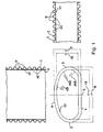
- FIG. 1 shows a schematic cross-sectional view of a first embodiment of the plastic pipe according to the invention with a vertical outer dimension 7 of 50 mm and a horizontal outer dimension 8 of 100 mm.
- the plane of symmetry is represented by a dash-dot line 3.
- the flat bottom wall 4 is at a Krümmungsinnenradius 14B of 15 mm in the side walls 5, and this at a radius of curvature 14A of 20 mm in the top wall 6, wherein the top wall 6 has a radius of curvature 15 of 85 mm.
- the transition between the bottom and side walls adjoins directly to the transition between the side and top wall, so that virtually no surface of the side wall 5 remains.
- the corrugated pipe is a corrugated pipe with parallel corrugation peaks 9 and valleys 10.
- the longitudinal profile of the corrugated pipes of the in FIG. 1 differ profile shown.
- FIG. 1 shows a preferred corrugated pipe with flattened wave crests 9; but there are also, for example, corrugated pipes conceivable in which the troughs 10 and 9 mountains are symmetrical.
- the radius of curvature 14A of the transitions between the top wall 6 and side walls 5 is greater, preferably about 30% to 70% greater, than the internal radius of curvature 14B of the transitions between the bottom wall 4 and the side walls 5. This optimizes the partly conflicting requirements for mechanical stability on the one hand and the low flow resistance on the other.
- the smaller radius of curvature in the region of the bottom wall creates a larger flow cross-section through an outward displacement of the corners, and the larger radius of curvature 14A at the transition to the top wall serves to better support this wall.
- FIG. 2 shows a second embodiment of the plastic pipe according to the invention with larger dimensions; the height 7 of the laid pipe is here 60 mm and its width 8 is 120 mm. With a constant wall thickness of about 5 mm thus results in a height inside dimension 12 of 50 mm and a width inside dimension 13 of 110 mm. Also in this embodiment, the transition between the bottom wall 4 and the side walls 5 connects almost directly to the transition between the side walls 5 and the top wall 6, so that practically only a narrow strip remains as the side wall 5. For the rest, the embodiment corresponds to FIG. 2 those of FIG. 1 ,
- FIG. 1 is designed for a flow rate of 25 m 3 / h at a flow rate of 2.26 m / s
- the embodiment of Figure 2 is provided for a flow rate of 52.2 m 3 / h at a flow rate of 2.9 m / s ,
- FIG. 3 shows schematic sectional views of a third embodiment of the plastic pipe according to the invention, which is designed for a flow rate of 55 m 3 / h at a flow rate of 2.9 m / s.
- the same height outside dimension 7 of 60 mm as the embodiment according to FIG. 2 The flow cross-section has been increased by choosing a larger outside width dimension of 130 mm and inside of 120 mm and, moreover, reducing the inside curvature radii 14A, 14B of the transitions between the bottom, side and top walls so that the corners are outward moved.
- the radius 15 of the curvature of the ceiling wall has been compared to the embodiment according to FIG. 2 increased.
- the increased flow cross-section is partly at the expense of mechanical stability compared to the above-acting mechanical compressive forces, wherein the embodiment shown still remains within the range of optimization according to the invention.
- the inner tube consists in a preferred embodiment of polyethylene. But there are also other plastic materials conceivable, such as polypropylene, the choice of the plastic material of the cost and other requirements, for example, for recycling, depends.
- the inner tube is thin and flexible. Its thickness in preferred embodiments is less than 1 mm, preferably less than 0.3 mm. In a preferred embodiment, the thickness of the inner tube is about 0.1 mm.
- the outer corrugated pipe is also made of polyethylene or polypropylene, for example. Admixtures are added to the plastic which serve its coloring, increased resistance to light and UV radiation and improved fire protection. For example, the plastic material is colored black.
- the production of the plastic pipes according to the invention is preferably carried out by coextrusion of the outer corrugated tube and the smooth inner tube such that the outer surfaces of the inner tube are firmly connected to the inner surfaces of the corrugated tube valleys.
- the materials of the corrugated pipe on the one hand and the inner tube on the other hand, as well as the process control during extrusion are chosen so that on the one hand to a sufficiently strong connection between the two components and on the other hand, the inner tube is not compressed, so that its inner surface remains smooth and even. It is also conceivable that the inner tube is connected to the outer corrugated tube so that it is under a tensile stress, which ensures a smoothing of the inner surface.
- a composite which additionally comprises an outer smooth hose on the outer sides of the corrugated pipe.
- an embodiment is conceivable which provides improved thermal insulation between the interior of the pipe and the environment.
- further layers are applied for thermal insulation outside of the corrugated pipe.
- the inner tube is constructed in multiple layers. It is also conceivable that the inner tube is connected by means of an adhesive layer with the corrugated tube.
- the inner tube is formed so that its inner sides are antistatic and / or antibacterial properties.
- the hose may for example consist of an antistatic material, for example, contain conductive particles.
- the inner surfaces may be coated or treated so as to have antistatic properties.
- the inner tube may be made of an antibacterial material, or its inner surfaces may be coated or treated so as to have antibacterial properties.
- a silver powder or silver granules could be extruded along with the plastic material. It could also be the necessary silver ions introduced by silver compounds in the plastic material or applied in the form of a coating on the insides.
- the plastic pipe according to the invention is preferably used for ventilation ducts in buildings, which are installed within the screed.
- the plastic pipes according to the invention are initially laid and fixed on a flat floor together with correspondingly adapted moldings, which allow connections and bends. Then the screed is poured, which encloses the plastic pipes.
Landscapes
- Engineering & Computer Science (AREA)
- General Engineering & Computer Science (AREA)
- Mechanical Engineering (AREA)
- Textile Engineering (AREA)
- Chemical & Material Sciences (AREA)
- Combustion & Propulsion (AREA)
- Rigid Pipes And Flexible Pipes (AREA)
Claims (5)
- Tube en matériau synthétique pour le transfert d'un fluide pour installations de climatisation et de ventilation, en particulier pour installation horizontale à l'intérieur d'une chape, constitué des éléments suivants :un tube ondulé flexible (1) d'une section transversale formée symétriquement par rapport à un plan de symétrie (3), dont la largeur en dimension interne (13) est, transversalement au plan de symétrie, supérieure à la hauteur en dimension interne (12) dans le plan de symétrie et dont la hauteur en dimension externe (7) ne dépasse pas une mesure prédéfinie, etun tuyau interne (2) raccordé aux surfaces internes des creux (10) du tube ondulé avec une surface interne (11) plane et lisse,caractérisé en ce que la section transversale est délimitée par une paroi de fond (4) plane, une paroi de recouvrement (6) opposée bombée en forme d'arc vers l'extérieur et des parois latérales (5) agencées entre elles, dans lequel le rayon (15) de la courbure de la paroi de recouvrement (6) correspondant à au moins 1,5 fois, mais au maximum à cinq fois, la hauteur en dimension interne (12), dans lequel la paroi de fond (4), les parois latérales (5) et la paroi de recouvrement (6) se fondent l'une dans l'autre en forme d'arc en section transversale de sorte qu'il résulte dans les transitions entre la paroi de fond (4) et les parois latérales (5), ainsi qu'entre les parois latérales (5) et la paroi de recouvrement (6), des rayons internes de courbure (14A, 14B) qui atteignent au moins un sixième de la hauteur en dimension interne.
- Tube en matériau synthétique selon la revendication 1, caractérisé en ce que le rayon (15) de la courbure de la paroi de recouvrement (6) correspond au moins au double, mais au maximum au triple, de la hauteur en dimension interne (12) et en ce que les rayons internes de courbure (14A, 14B) atteignent au moins un quart de la hauteur en dimension interne (12) dans les transitions entre la paroi de fond (4) et les parois latérales (5) et entre les parois latérales (5) et la paroi de recouvrement (6).
- Tube en matériau synthétique selon la revendication 2, caractérisé en ce que la mesure prédéfinie, qui ne dépasse pas la hauteur en dimension externe (7), se situe entre 50 et 60 mm et la hauteur en dimension interne (12) se situe entre 40 et 50 mm, dans lequel le rayon (15) de la courbure de la paroi de recouvrement se situe entre 80 mm et 150 mm et les rayons internes de courbure atteignent au moins 10 mm dans les transitions entre les parois (4, 5, 6).
- Tube en matériau synthétique selon l'une quelconque des revendications 1 à 3, caractérisé en ce que le tuyau interne (2) est constitué d'un matériau antistatique et/ou sa surface interne (11) est revêtue ou traitée de manière à présenter des propriétés antistatiques.
- Tube en matériau synthétique selon l'une quelconque des revendications 1 à 4, caractérisé en ce que le tuyau interne (2) est constitué d'un matériau à action antibactérienne et/ou sa surface interne (11) est revêtue ou traitée de manière à présenter des propriétés antibactériennes.
Applications Claiming Priority (1)
| Application Number | Priority Date | Filing Date | Title |
|---|---|---|---|
| DE102008002186A DE102008002186B4 (de) | 2008-06-03 | 2008-06-03 | Kunststoffwellrohr mit einem abgeflachten Querschnitt |
Publications (2)
| Publication Number | Publication Date |
|---|---|
| EP2131114A1 EP2131114A1 (fr) | 2009-12-09 |
| EP2131114B1 true EP2131114B1 (fr) | 2010-07-28 |
Family
ID=41063317
Family Applications (1)
| Application Number | Title | Priority Date | Filing Date |
|---|---|---|---|
| EP09156181A Active EP2131114B1 (fr) | 2008-06-03 | 2009-03-25 | Tube ondulé en plastique doté d'une section transversale aplatie |
Country Status (5)
| Country | Link |
|---|---|
| EP (1) | EP2131114B1 (fr) |
| AT (1) | ATE475847T1 (fr) |
| DE (2) | DE102008002186B4 (fr) |
| DK (1) | DK2131114T3 (fr) |
| ES (1) | ES2348970T3 (fr) |
Cited By (1)
| Publication number | Priority date | Publication date | Assignee | Title |
|---|---|---|---|---|
| DE202010012660U1 (de) | 2010-09-16 | 2010-12-02 | Stiebel Eltron Gmbh & Co. Kg | Rohr zur Leitung eines Fluids |
Families Citing this family (4)
| Publication number | Priority date | Publication date | Assignee | Title |
|---|---|---|---|---|
| EP2620683B1 (fr) | 2012-01-24 | 2015-03-04 | Ralph Peter Hegler | Tuyau composite pour la technique de climatisation et d'aération |
| SI24277A (sl) * | 2013-01-22 | 2014-07-31 | Timplast D.O.O. | Naprava za prezračevanje z rekuperacijo prednostno nadometni stropni razdelilec |
| FR3058205B1 (fr) * | 2016-10-28 | 2019-01-25 | Alstom Transport Technologies | Gaine d'air, notamment pour un dispositif de climatisation destine a equiper un vehicule ferroviaire |
| DE102018221508A1 (de) * | 2018-12-12 | 2020-06-18 | Ralph Peter Hegler | Verbundrohr für Klima- und Lüftungstechnik |
Family Cites Families (4)
| Publication number | Priority date | Publication date | Assignee | Title |
|---|---|---|---|---|
| FI20021198L (fi) * | 2002-06-19 | 2003-12-20 | Uponor Innovation Ab | Ilmanvaihtokanava ja sovitelma ilmanvaihtokanavan yhteydessä |
| DE202005005056U1 (de) * | 2005-03-31 | 2005-06-02 | Hegler, Ralph Peter, Dr.-Ing. | Kunststoff-Rohr für Klima- und Lüftungs-Technik |
| DE202005007835U1 (de) * | 2005-05-19 | 2005-07-21 | Zehnder Verkaufs- Und Verwaltungs-Ag | Rohr |
| DE102007034244A1 (de) * | 2007-07-23 | 2009-01-29 | Fränkische Rohrwerke Gebr. Kirchner Gmbh & Co. Kg | Rohr und Kombination zweier derartiger Rohre |
-
2008
- 2008-06-03 DE DE102008002186A patent/DE102008002186B4/de not_active Expired - Fee Related
-
2009
- 2009-03-25 DK DK09156181.1T patent/DK2131114T3/da active
- 2009-03-25 DE DE502009000050T patent/DE502009000050D1/de active Active
- 2009-03-25 AT AT09156181T patent/ATE475847T1/de active
- 2009-03-25 EP EP09156181A patent/EP2131114B1/fr active Active
- 2009-03-25 ES ES09156181T patent/ES2348970T3/es active Active
Cited By (3)
| Publication number | Priority date | Publication date | Assignee | Title |
|---|---|---|---|---|
| DE202010012660U1 (de) | 2010-09-16 | 2010-12-02 | Stiebel Eltron Gmbh & Co. Kg | Rohr zur Leitung eines Fluids |
| EP2431642A2 (fr) | 2010-09-16 | 2012-03-21 | STIEBEL ELTRON GmbH & Co. KG | Tuyau de guidage d'un fluide |
| EP2431642A3 (fr) * | 2010-09-16 | 2016-10-19 | STIEBEL ELTRON GmbH & Co. KG | Tuyau de guidage d'un fluide |
Also Published As
| Publication number | Publication date |
|---|---|
| EP2131114A1 (fr) | 2009-12-09 |
| ATE475847T1 (de) | 2010-08-15 |
| DE502009000050D1 (de) | 2010-09-09 |
| DK2131114T3 (da) | 2010-11-22 |
| DE102008002186A1 (de) | 2010-03-25 |
| DE102008002186B4 (de) | 2012-04-12 |
| ES2348970T3 (es) | 2010-12-17 |
Similar Documents
| Publication | Publication Date | Title |
|---|---|---|
| DE10225281C1 (de) | Container | |
| EP2431642B1 (fr) | Tuyau de guidage d'un fluide | |
| EP2870313B1 (fr) | Entretoise destinée à des vitrages isolants | |
| EP1370794B1 (fr) | Piece d'isolation sous forme de panneau ou de cylindre creux | |
| EP2131114B1 (fr) | Tube ondulé en plastique doté d'une section transversale aplatie | |
| EP0477484A1 (fr) | Faisceau de conduits tubulaires pour câbles et méthode de fabrication d'un ensemble de tubes pour faisceau de conduits tubulaires pour câbles | |
| AT513069A1 (de) | Vorrichtung zum Klimatisieren eines Raumes | |
| DE102016214312A1 (de) | Kunststoffschlauch für ein Sauggerät | |
| WO2008151771A2 (fr) | Conduite tubulaire destinée à connecter un collecteur solaire à un réservoir d'eau | |
| EP0158188B2 (fr) | Structure de bâtiment avec des conduites posées sur la dalle en béton | |
| EP1724508B1 (fr) | Tuyau | |
| DE4224743C1 (de) | Kabelschutzrohr | |
| DE10021523C2 (de) | Rohr | |
| EP2458295A1 (fr) | Element de conduit pliante avec encoches longitudinales le long d'arrêtes pliées | |
| EP4023919B1 (fr) | Conduite de fluide | |
| DE202005005056U1 (de) | Kunststoff-Rohr für Klima- und Lüftungs-Technik | |
| EP2620683A1 (fr) | Tuyau composite pour la technique de climatisation et d'aération | |
| EP3581835A1 (fr) | Système de distribution d'air pourvu de canalisation | |
| WO2024002854A1 (fr) | Composant multicouche pour un toit, procédé de fabrication d'un composant multicouche et utilisation de bandes de béton à armature textile | |
| EP3688358A1 (fr) | Tuyau pour systèmes de distribution d'air | |
| EP0773399B1 (fr) | Tuyau ou section de tuyau en matériau thermoplastique | |
| DE19920034A1 (de) | Armiertes Thermoplastrohr | |
| DE2801055A1 (de) | Flexibler und zusammendrueckbarer kanal und verfahren zu seiner herstellung | |
| EP2423551B1 (fr) | Tuyau ondulé composite | |
| DE10361421A1 (de) | Raumbegrenzungselement |
Legal Events
| Date | Code | Title | Description |
|---|---|---|---|
| PUAI | Public reference made under article 153(3) epc to a published international application that has entered the european phase |
Free format text: ORIGINAL CODE: 0009012 |
|
| AK | Designated contracting states |
Kind code of ref document: A1 Designated state(s): AT BE BG CH CY CZ DE DK EE ES FI FR GB GR HR HU IE IS IT LI LT LU LV MC MK MT NL NO PL PT RO SE SI SK TR |
|
| AX | Request for extension of the european patent |
Extension state: AL BA RS |
|
| 17P | Request for examination filed |
Effective date: 20091203 |
|
| GRAP | Despatch of communication of intention to grant a patent |
Free format text: ORIGINAL CODE: EPIDOSNIGR1 |
|
| GRAS | Grant fee paid |
Free format text: ORIGINAL CODE: EPIDOSNIGR3 |
|
| GRAA | (expected) grant |
Free format text: ORIGINAL CODE: 0009210 |
|
| AK | Designated contracting states |
Kind code of ref document: B1 Designated state(s): AT BE BG CH CY CZ DE DK EE ES FI FR GB GR HR HU IE IS IT LI LT LU LV MC MK MT NL NO PL PT RO SE SI SK TR |
|
| REG | Reference to a national code |
Ref country code: GB Ref legal event code: FG4D Free format text: NOT ENGLISH |
|
| REG | Reference to a national code |
Ref country code: CH Ref legal event code: EP |
|
| AKX | Designation fees paid |
Designated state(s): AT BE BG CH CY CZ DE DK EE ES FI FR GB GR HR HU IE IS IT LI LT LU LV MC MK MT NL NO PL PT RO SE SI SK TR |
|
| REG | Reference to a national code |
Ref country code: IE Ref legal event code: FG4D Free format text: LANGUAGE OF EP DOCUMENT: GERMAN |
|
| REF | Corresponds to: |
Ref document number: 502009000050 Country of ref document: DE Date of ref document: 20100909 Kind code of ref document: P |
|
| REG | Reference to a national code |
Ref country code: NL Ref legal event code: T3 |
|
| REG | Reference to a national code |
Ref country code: DK Ref legal event code: T3 |
|
| REG | Reference to a national code |
Ref country code: ES Ref legal event code: FG2A Effective date: 20101203 |
|
| LTIE | Lt: invalidation of european patent or patent extension |
Effective date: 20100728 |
|
| PG25 | Lapsed in a contracting state [announced via postgrant information from national office to epo] |
Ref country code: NO Free format text: LAPSE BECAUSE OF FAILURE TO SUBMIT A TRANSLATION OF THE DESCRIPTION OR TO PAY THE FEE WITHIN THE PRESCRIBED TIME-LIMIT Effective date: 20101028 Ref country code: FI Free format text: LAPSE BECAUSE OF FAILURE TO SUBMIT A TRANSLATION OF THE DESCRIPTION OR TO PAY THE FEE WITHIN THE PRESCRIBED TIME-LIMIT Effective date: 20100728 Ref country code: LT Free format text: LAPSE BECAUSE OF FAILURE TO SUBMIT A TRANSLATION OF THE DESCRIPTION OR TO PAY THE FEE WITHIN THE PRESCRIBED TIME-LIMIT Effective date: 20100728 |
|
| PG25 | Lapsed in a contracting state [announced via postgrant information from national office to epo] |
Ref country code: BG Free format text: LAPSE BECAUSE OF FAILURE TO SUBMIT A TRANSLATION OF THE DESCRIPTION OR TO PAY THE FEE WITHIN THE PRESCRIBED TIME-LIMIT Effective date: 20101028 Ref country code: IS Free format text: LAPSE BECAUSE OF FAILURE TO SUBMIT A TRANSLATION OF THE DESCRIPTION OR TO PAY THE FEE WITHIN THE PRESCRIBED TIME-LIMIT Effective date: 20101128 Ref country code: PL Free format text: LAPSE BECAUSE OF FAILURE TO SUBMIT A TRANSLATION OF THE DESCRIPTION OR TO PAY THE FEE WITHIN THE PRESCRIBED TIME-LIMIT Effective date: 20100728 Ref country code: SI Free format text: LAPSE BECAUSE OF FAILURE TO SUBMIT A TRANSLATION OF THE DESCRIPTION OR TO PAY THE FEE WITHIN THE PRESCRIBED TIME-LIMIT Effective date: 20100728 Ref country code: HR Free format text: LAPSE BECAUSE OF FAILURE TO SUBMIT A TRANSLATION OF THE DESCRIPTION OR TO PAY THE FEE WITHIN THE PRESCRIBED TIME-LIMIT Effective date: 20100728 Ref country code: CY Free format text: LAPSE BECAUSE OF FAILURE TO SUBMIT A TRANSLATION OF THE DESCRIPTION OR TO PAY THE FEE WITHIN THE PRESCRIBED TIME-LIMIT Effective date: 20100728 |
|
| PG25 | Lapsed in a contracting state [announced via postgrant information from national office to epo] |
Ref country code: LV Free format text: LAPSE BECAUSE OF FAILURE TO SUBMIT A TRANSLATION OF THE DESCRIPTION OR TO PAY THE FEE WITHIN THE PRESCRIBED TIME-LIMIT Effective date: 20100728 Ref country code: GR Free format text: LAPSE BECAUSE OF FAILURE TO SUBMIT A TRANSLATION OF THE DESCRIPTION OR TO PAY THE FEE WITHIN THE PRESCRIBED TIME-LIMIT Effective date: 20101029 Ref country code: SE Free format text: LAPSE BECAUSE OF FAILURE TO SUBMIT A TRANSLATION OF THE DESCRIPTION OR TO PAY THE FEE WITHIN THE PRESCRIBED TIME-LIMIT Effective date: 20100728 |
|
| PG25 | Lapsed in a contracting state [announced via postgrant information from national office to epo] |
Ref country code: CZ Free format text: LAPSE BECAUSE OF FAILURE TO SUBMIT A TRANSLATION OF THE DESCRIPTION OR TO PAY THE FEE WITHIN THE PRESCRIBED TIME-LIMIT Effective date: 20100728 Ref country code: SK Free format text: LAPSE BECAUSE OF FAILURE TO SUBMIT A TRANSLATION OF THE DESCRIPTION OR TO PAY THE FEE WITHIN THE PRESCRIBED TIME-LIMIT Effective date: 20100728 Ref country code: RO Free format text: LAPSE BECAUSE OF FAILURE TO SUBMIT A TRANSLATION OF THE DESCRIPTION OR TO PAY THE FEE WITHIN THE PRESCRIBED TIME-LIMIT Effective date: 20100728 Ref country code: EE Free format text: LAPSE BECAUSE OF FAILURE TO SUBMIT A TRANSLATION OF THE DESCRIPTION OR TO PAY THE FEE WITHIN THE PRESCRIBED TIME-LIMIT Effective date: 20100728 |
|
| PLBE | No opposition filed within time limit |
Free format text: ORIGINAL CODE: 0009261 |
|
| STAA | Information on the status of an ep patent application or granted ep patent |
Free format text: STATUS: NO OPPOSITION FILED WITHIN TIME LIMIT |
|
| 26N | No opposition filed |
Effective date: 20110429 |
|
| REG | Reference to a national code |
Ref country code: DE Ref legal event code: R097 Ref document number: 502009000050 Country of ref document: DE Effective date: 20110429 |
|
| PG25 | Lapsed in a contracting state [announced via postgrant information from national office to epo] |
Ref country code: MC Free format text: LAPSE BECAUSE OF NON-PAYMENT OF DUE FEES Effective date: 20110331 |
|
| PG25 | Lapsed in a contracting state [announced via postgrant information from national office to epo] |
Ref country code: MT Free format text: LAPSE BECAUSE OF FAILURE TO SUBMIT A TRANSLATION OF THE DESCRIPTION OR TO PAY THE FEE WITHIN THE PRESCRIBED TIME-LIMIT Effective date: 20100728 |
|
| PG25 | Lapsed in a contracting state [announced via postgrant information from national office to epo] |
Ref country code: MK Free format text: LAPSE BECAUSE OF FAILURE TO SUBMIT A TRANSLATION OF THE DESCRIPTION OR TO PAY THE FEE WITHIN THE PRESCRIBED TIME-LIMIT Effective date: 20100728 |
|
| PG25 | Lapsed in a contracting state [announced via postgrant information from national office to epo] |
Ref country code: LU Free format text: LAPSE BECAUSE OF NON-PAYMENT OF DUE FEES Effective date: 20110325 |
|
| PG25 | Lapsed in a contracting state [announced via postgrant information from national office to epo] |
Ref country code: PT Free format text: LAPSE BECAUSE OF NON-PAYMENT OF DUE FEES Effective date: 20100728 |
|
| PG25 | Lapsed in a contracting state [announced via postgrant information from national office to epo] |
Ref country code: TR Free format text: LAPSE BECAUSE OF FAILURE TO SUBMIT A TRANSLATION OF THE DESCRIPTION OR TO PAY THE FEE WITHIN THE PRESCRIBED TIME-LIMIT Effective date: 20100728 |
|
| PG25 | Lapsed in a contracting state [announced via postgrant information from national office to epo] |
Ref country code: HU Free format text: LAPSE BECAUSE OF FAILURE TO SUBMIT A TRANSLATION OF THE DESCRIPTION OR TO PAY THE FEE WITHIN THE PRESCRIBED TIME-LIMIT Effective date: 20100728 |
|
| REG | Reference to a national code |
Ref country code: FR Ref legal event code: PLFP Year of fee payment: 7 |
|
| REG | Reference to a national code |
Ref country code: FR Ref legal event code: PLFP Year of fee payment: 8 |
|
| REG | Reference to a national code |
Ref country code: FR Ref legal event code: PLFP Year of fee payment: 9 |
|
| REG | Reference to a national code |
Ref country code: FR Ref legal event code: PLFP Year of fee payment: 10 |
|
| PGFP | Annual fee paid to national office [announced via postgrant information from national office to epo] |
Ref country code: DK Payment date: 20200324 Year of fee payment: 12 |
|
| PGFP | Annual fee paid to national office [announced via postgrant information from national office to epo] |
Ref country code: CH Payment date: 20200319 Year of fee payment: 12 |
|
| REG | Reference to a national code |
Ref country code: CH Ref legal event code: PL |
|
| REG | Reference to a national code |
Ref country code: DK Ref legal event code: EBP Effective date: 20210331 |
|
| PG25 | Lapsed in a contracting state [announced via postgrant information from national office to epo] |
Ref country code: LI Free format text: LAPSE BECAUSE OF NON-PAYMENT OF DUE FEES Effective date: 20210331 Ref country code: CH Free format text: LAPSE BECAUSE OF NON-PAYMENT OF DUE FEES Effective date: 20210331 |
|
| PG25 | Lapsed in a contracting state [announced via postgrant information from national office to epo] |
Ref country code: DK Free format text: LAPSE BECAUSE OF NON-PAYMENT OF DUE FEES Effective date: 20210331 |
|
| P01 | Opt-out of the competence of the unified patent court (upc) registered |
Effective date: 20230414 |
|
| PGFP | Annual fee paid to national office [announced via postgrant information from national office to epo] |
Ref country code: NL Payment date: 20240320 Year of fee payment: 16 Ref country code: IE Payment date: 20240321 Year of fee payment: 16 |
|
| PGFP | Annual fee paid to national office [announced via postgrant information from national office to epo] |
Ref country code: AT Payment date: 20240321 Year of fee payment: 16 |
|
| PGFP | Annual fee paid to national office [announced via postgrant information from national office to epo] |
Ref country code: DE Payment date: 20240331 Year of fee payment: 16 Ref country code: GB Payment date: 20240320 Year of fee payment: 16 |
|
| PGFP | Annual fee paid to national office [announced via postgrant information from national office to epo] |
Ref country code: IT Payment date: 20240329 Year of fee payment: 16 Ref country code: FR Payment date: 20240322 Year of fee payment: 16 Ref country code: BE Payment date: 20240320 Year of fee payment: 16 |
|
| PGFP | Annual fee paid to national office [announced via postgrant information from national office to epo] |
Ref country code: ES Payment date: 20240426 Year of fee payment: 16 |
|
| REG | Reference to a national code |
Ref country code: DE Ref legal event code: R119 Ref document number: 502009000050 Country of ref document: DE |
|
| REG | Reference to a national code |
Ref country code: NL Ref legal event code: MM Effective date: 20250401 |
|
| REG | Reference to a national code |
Ref country code: AT Ref legal event code: MM01 Ref document number: 475847 Country of ref document: AT Kind code of ref document: T Effective date: 20250325 |
|
| GBPC | Gb: european patent ceased through non-payment of renewal fee |
Effective date: 20250325 |
|
| REG | Reference to a national code |
Ref country code: BE Ref legal event code: MM Effective date: 20250331 |
|
| PG25 | Lapsed in a contracting state [announced via postgrant information from national office to epo] |
Ref country code: NL Free format text: LAPSE BECAUSE OF NON-PAYMENT OF DUE FEES Effective date: 20250401 |
|
| PG25 | Lapsed in a contracting state [announced via postgrant information from national office to epo] |
Ref country code: DE Free format text: LAPSE BECAUSE OF NON-PAYMENT OF DUE FEES Effective date: 20251001 |
|
| PG25 | Lapsed in a contracting state [announced via postgrant information from national office to epo] |
Ref country code: GB Free format text: LAPSE BECAUSE OF NON-PAYMENT OF DUE FEES Effective date: 20250325 |
|
| PG25 | Lapsed in a contracting state [announced via postgrant information from national office to epo] |
Ref country code: AT Free format text: LAPSE BECAUSE OF NON-PAYMENT OF DUE FEES Effective date: 20250325 |
|
| PG25 | Lapsed in a contracting state [announced via postgrant information from national office to epo] |
Ref country code: FR Free format text: LAPSE BECAUSE OF NON-PAYMENT OF DUE FEES Effective date: 20250331 Ref country code: IT Free format text: LAPSE BECAUSE OF NON-PAYMENT OF DUE FEES Effective date: 20250325 |
|
| PG25 | Lapsed in a contracting state [announced via postgrant information from national office to epo] |
Ref country code: BE Free format text: LAPSE BECAUSE OF NON-PAYMENT OF DUE FEES Effective date: 20250331 |
|
| PG25 | Lapsed in a contracting state [announced via postgrant information from national office to epo] |
Ref country code: IE Free format text: LAPSE BECAUSE OF NON-PAYMENT OF DUE FEES Effective date: 20250325 |