EP2431642A2 - Tuyau de guidage d'un fluide - Google Patents
Tuyau de guidage d'un fluide Download PDFInfo
- Publication number
- EP2431642A2 EP2431642A2 EP11007561A EP11007561A EP2431642A2 EP 2431642 A2 EP2431642 A2 EP 2431642A2 EP 11007561 A EP11007561 A EP 11007561A EP 11007561 A EP11007561 A EP 11007561A EP 2431642 A2 EP2431642 A2 EP 2431642A2
- Authority
- EP
- European Patent Office
- Prior art keywords
- tube
- curvature
- region
- pipe
- radius
- Prior art date
- Legal status (The legal status is an assumption and is not a legal conclusion. Google has not performed a legal analysis and makes no representation as to the accuracy of the status listed.)
- Granted
Links
Images





Classifications
-
- F—MECHANICAL ENGINEERING; LIGHTING; HEATING; WEAPONS; BLASTING
- F16—ENGINEERING ELEMENTS AND UNITS; GENERAL MEASURES FOR PRODUCING AND MAINTAINING EFFECTIVE FUNCTIONING OF MACHINES OR INSTALLATIONS; THERMAL INSULATION IN GENERAL
- F16L—PIPES; JOINTS OR FITTINGS FOR PIPES; SUPPORTS FOR PIPES, CABLES OR PROTECTIVE TUBING; MEANS FOR THERMAL INSULATION IN GENERAL
- F16L9/00—Rigid pipes
- F16L9/006—Rigid pipes specially profiled
-
- F—MECHANICAL ENGINEERING; LIGHTING; HEATING; WEAPONS; BLASTING
- F16—ENGINEERING ELEMENTS AND UNITS; GENERAL MEASURES FOR PRODUCING AND MAINTAINING EFFECTIVE FUNCTIONING OF MACHINES OR INSTALLATIONS; THERMAL INSULATION IN GENERAL
- F16L—PIPES; JOINTS OR FITTINGS FOR PIPES; SUPPORTS FOR PIPES, CABLES OR PROTECTIVE TUBING; MEANS FOR THERMAL INSULATION IN GENERAL
- F16L11/00—Hoses, i.e. flexible pipes
- F16L11/04—Hoses, i.e. flexible pipes made of rubber or flexible plastics
- F16L11/11—Hoses, i.e. flexible pipes made of rubber or flexible plastics with corrugated wall
-
- F—MECHANICAL ENGINEERING; LIGHTING; HEATING; WEAPONS; BLASTING
- F16—ENGINEERING ELEMENTS AND UNITS; GENERAL MEASURES FOR PRODUCING AND MAINTAINING EFFECTIVE FUNCTIONING OF MACHINES OR INSTALLATIONS; THERMAL INSULATION IN GENERAL
- F16L—PIPES; JOINTS OR FITTINGS FOR PIPES; SUPPORTS FOR PIPES, CABLES OR PROTECTIVE TUBING; MEANS FOR THERMAL INSULATION IN GENERAL
- F16L11/00—Hoses, i.e. flexible pipes
- F16L11/04—Hoses, i.e. flexible pipes made of rubber or flexible plastics
- F16L11/12—Hoses, i.e. flexible pipes made of rubber or flexible plastics with arrangements for particular purposes, e.g. specially profiled, with protecting layer, heated, electrically conducting
- F16L11/121—Hoses, i.e. flexible pipes made of rubber or flexible plastics with arrangements for particular purposes, e.g. specially profiled, with protecting layer, heated, electrically conducting specially profiled cross sections
-
- F—MECHANICAL ENGINEERING; LIGHTING; HEATING; WEAPONS; BLASTING
- F16—ENGINEERING ELEMENTS AND UNITS; GENERAL MEASURES FOR PRODUCING AND MAINTAINING EFFECTIVE FUNCTIONING OF MACHINES OR INSTALLATIONS; THERMAL INSULATION IN GENERAL
- F16L—PIPES; JOINTS OR FITTINGS FOR PIPES; SUPPORTS FOR PIPES, CABLES OR PROTECTIVE TUBING; MEANS FOR THERMAL INSULATION IN GENERAL
- F16L11/00—Hoses, i.e. flexible pipes
- F16L11/14—Hoses, i.e. flexible pipes made of rigid material, e.g. metal or hard plastics
- F16L11/15—Hoses, i.e. flexible pipes made of rigid material, e.g. metal or hard plastics corrugated
-
- F—MECHANICAL ENGINEERING; LIGHTING; HEATING; WEAPONS; BLASTING
- F16—ENGINEERING ELEMENTS AND UNITS; GENERAL MEASURES FOR PRODUCING AND MAINTAINING EFFECTIVE FUNCTIONING OF MACHINES OR INSTALLATIONS; THERMAL INSULATION IN GENERAL
- F16L—PIPES; JOINTS OR FITTINGS FOR PIPES; SUPPORTS FOR PIPES, CABLES OR PROTECTIVE TUBING; MEANS FOR THERMAL INSULATION IN GENERAL
- F16L9/00—Rigid pipes
- F16L9/02—Rigid pipes of metal
- F16L9/06—Corrugated pipes
-
- F—MECHANICAL ENGINEERING; LIGHTING; HEATING; WEAPONS; BLASTING
- F24—HEATING; RANGES; VENTILATING
- F24D—DOMESTIC- OR SPACE-HEATING SYSTEMS, e.g. CENTRAL HEATING SYSTEMS; DOMESTIC HOT-WATER SUPPLY SYSTEMS; ELEMENTS OR COMPONENTS THEREFOR
- F24D3/00—Hot-water central heating systems
- F24D3/12—Tube and panel arrangements for ceiling, wall, or underfloor heating
- F24D3/14—Tube and panel arrangements for ceiling, wall, or underfloor heating incorporated in a ceiling, wall or floor
- F24D3/146—Tubes specially adapted for underfloor heating
-
- B—PERFORMING OPERATIONS; TRANSPORTING
- B29—WORKING OF PLASTICS; WORKING OF SUBSTANCES IN A PLASTIC STATE IN GENERAL
- B29C—SHAPING OR JOINING OF PLASTICS; SHAPING OF MATERIAL IN A PLASTIC STATE, NOT OTHERWISE PROVIDED FOR; AFTER-TREATMENT OF THE SHAPED PRODUCTS, e.g. REPAIRING
- B29C48/00—Extrusion moulding, i.e. expressing the moulding material through a die or nozzle which imparts the desired form; Apparatus therefor
- B29C48/03—Extrusion moulding, i.e. expressing the moulding material through a die or nozzle which imparts the desired form; Apparatus therefor characterised by the shape of the extruded material at extrusion
- B29C48/09—Articles with cross-sections having partially or fully enclosed cavities, e.g. pipes or channels
-
- B—PERFORMING OPERATIONS; TRANSPORTING
- B29—WORKING OF PLASTICS; WORKING OF SUBSTANCES IN A PLASTIC STATE IN GENERAL
- B29C—SHAPING OR JOINING OF PLASTICS; SHAPING OF MATERIAL IN A PLASTIC STATE, NOT OTHERWISE PROVIDED FOR; AFTER-TREATMENT OF THE SHAPED PRODUCTS, e.g. REPAIRING
- B29C48/00—Extrusion moulding, i.e. expressing the moulding material through a die or nozzle which imparts the desired form; Apparatus therefor
- B29C48/03—Extrusion moulding, i.e. expressing the moulding material through a die or nozzle which imparts the desired form; Apparatus therefor characterised by the shape of the extruded material at extrusion
- B29C48/13—Articles with a cross-section varying in the longitudinal direction, e.g. corrugated pipes
-
- B—PERFORMING OPERATIONS; TRANSPORTING
- B29—WORKING OF PLASTICS; WORKING OF SUBSTANCES IN A PLASTIC STATE IN GENERAL
- B29C—SHAPING OR JOINING OF PLASTICS; SHAPING OF MATERIAL IN A PLASTIC STATE, NOT OTHERWISE PROVIDED FOR; AFTER-TREATMENT OF THE SHAPED PRODUCTS, e.g. REPAIRING
- B29C48/00—Extrusion moulding, i.e. expressing the moulding material through a die or nozzle which imparts the desired form; Apparatus therefor
- B29C48/25—Component parts, details or accessories; Auxiliary operations
- B29C48/30—Extrusion nozzles or dies
- B29C48/303—Extrusion nozzles or dies using dies or die parts movable in a closed circuit, e.g. mounted on movable endless support
-
- Y—GENERAL TAGGING OF NEW TECHNOLOGICAL DEVELOPMENTS; GENERAL TAGGING OF CROSS-SECTIONAL TECHNOLOGIES SPANNING OVER SEVERAL SECTIONS OF THE IPC; TECHNICAL SUBJECTS COVERED BY FORMER USPC CROSS-REFERENCE ART COLLECTIONS [XRACs] AND DIGESTS
- Y02—TECHNOLOGIES OR APPLICATIONS FOR MITIGATION OR ADAPTATION AGAINST CLIMATE CHANGE
- Y02B—CLIMATE CHANGE MITIGATION TECHNOLOGIES RELATED TO BUILDINGS, e.g. HOUSING, HOUSE APPLIANCES OR RELATED END-USER APPLICATIONS
- Y02B30/00—Energy efficient heating, ventilation or air conditioning [HVAC]
Definitions
- the invention relates to a pipe for conducting a fluid, comprising a bottom wall, side connections and a ceiling wall.
- Such pipes are used in various areas, for example, as a sewer pipe or as an air duct in air conditioning and ventilation systems.
- a sewer pipe or as an air duct in air conditioning and ventilation systems.
- such a pipe is preferably laid horizontally within a screed of a building.
- the EP 2 019 242 A2 shows a tube having a cross section with a extending over the entire width of the tube rectilinear side, the two ends are connected by a curved like curved side.
- a plastic pipe for forwarding a fluid for air conditioning or ventilation systems which consists of a flexible corrugated pipe with a symmetrical to a plane of symmetry formed cross-section.
- the cross-section is delimited by a flat bottom wall and an opposite arcuately outwardly curved top wall and side walls arranged therebetween, the radius of curvature of the top wall being at least 1.5 times, but at most five times thecardininnenabunk corresponds.
- the bottom wall, the side walls and the ceiling walls go arcuately into each other.
- the present invention seeks to provide a pipe for conducting a fluid, on the one hand has a large flow cross-section, but on the other hand is static stable and resistant to cumbersome loads when installed within a screed. Furthermore, a pipe is to be provided which is compact and stackable and is easy to install within a screed.
- the invention has the object to provide a tube that is easily bendable.
- the top wall at least a first region and a second region, wherein the regions are interconnected and have different geometries.
- such a pipe is used in home appliances or systems, for example, for water pipe or as a heating pipe for a floor or wall heating.
- the pipe is used within a domestic appliance for the conduction of a fluid, for example for the connection of components of the device or for connection to a fluid network.
- the tube is used in a water heater or a hot water storage, which are connected via a flexible pipe to a water network.
- the tube is preferably used in a heat pump for fluid line, in particular of refrigerant, water or other heat transfer medium, for example for connection to a heating or service water system.
- the tube is used within a solar system, in particular for the connections and connection of collectors or the line of a heat transfer medium.
- the tube is used for the air duct in an air conditioning or ventilation system.
- the pipe is preferably laid within a screed.
- the width of the tube is about 100 to 150 mm, in particular about 130 to 140 mm, in particular 132.8 mm.
- the height of the tube is preferably about 40 to 60 mm, in particular about 50 to 55 mm, in particular 52 mm.
- the width of the tube is 132.8 mm and the height 52 mm.
- the tube consists of a corrugated tube with wave crests and troughs.
- an inner tube with a flat, smooth inner surface is preferably arranged, which is connected to the troughs.
- the wave crests preferably have a width of about 2 to 6 mm, in particular about 3 to 4 mm, in particular about 3.4 mm.
- the wave crests are arranged at a distance of about 4 to 8 mm, in particular about 5 to 6 mm, in particular about 5.7 mm, measured from the vertex, from each other.
- the height of the wave crests is preferably about 3 to 6 mm, in particular about 4 to 5 mm, preferably about 4.5 mm.
- the distance of the wave crests is about 5.7 mm, the width of the wave crests about 3.4 mm and the height of the wave crests about 4.5 mm.
- the tube and the inner tube made of a thermoplastic material which is capable of extrusion, preferably of polyethylene or polypropylene.
- the outer tube of high density polyethylene with the technical name PE-HD and the inner tube of low density polyethylene with the technical name PE-LD are provided.
- the outer tube made of PE-HD and the inner tube of ethylene vinyl acetate with the technical name EVA.
- the outer tube made of PE-HD and the inner tube made of PE-MD are identical to a further embodiment.
- the outer tube made of PE-MD and the inner tube made of EVA are identical to each other.
- both the outer tube and the inner tube made of PE-HD or PE-MD.
- the outer tube made of PE-LD and the inner tube made of PE-LD or EVA are identical to a further embodiment.
- the outer tube of Polyproplylen with the technical name PP and the inner tube of PE-LD, PP or EVA.
- the PE-HD has a density of about 940-970 kg / m 3 , the PE-MD of about 930-940 kg / m 3 , the PE-LD of about 915-930 kg / m 3 , the PP of about 900-915 kg / m 3 and the EVA of about 940 kg / m 3 on.
- the PE-HD has a melting point of 135 ° C, the PE-MD of 125 ° C, the PE-LD of 110 ° C, the PP of 160 ° C and the EVA of 105 ° C.
- the melting points of the materials preferably differ by a maximum of about 50 ° C, preferably from 0 ° C to about 30 ° C. This ensures that connect the outer tube and inner tube well together and the inner tube does not peel off again at a later date.
- the tube consists of a metal corrugated tube, preferably made of stainless steel, copper, aluminum or brass, in which an inner tube made of a thermoplastic extrusion-grade plastic or a metal foil, for example made of aluminum or stainless steel, inserted, in particular glued or welded.
- the top wall is arcuately curved, wherein the geometries are different in that the first area and the second area have different radii of curvature. This gives the pipe a large flow area, but remains resistant to treading loads.
- the radius of curvature of the first region is as large as possible and the radius of curvature of the second region is chosen to be as small as possible.
- the first radius of curvature corresponds to at least 5.5 times the height inside dimension of the tube and the second radius of curvature at most 1.4 times the height inside dimension.
- the cross section of the ceiling wall is given a largely trapezoidal shape.
- the first radius of curvature approaches infinity, so that the first area is made almost flat.
- Another embodiment represents a negative radius of curvature, ie an inward curvature, whereby the stackability of the tube is improved.
- the second area of the top wall is adjoined by a third area, which preferably has a third radius of curvature.
- a third area which preferably has a third radius of curvature.
- first area and the second area have different geometries insofar as the first area and the second area are formed by straight lines of different inclination.
- the ceiling wall is replaced by a roof-shaped cross-section.
- Advantageous embodiments of the invention are for example a gable roof shape, a pent roof shape or a hipped roof shape.
- the different geometries are formed by different shapes.
- the first area is curved and the second area is flat or vice versa.
- first region and the second region are formed by different parabolas.
- the top wall has different wall thicknesses in the first area and in the second area.
- the height of the wall is formed larger the first area, whereby the tube receives additional stability.
- the height of the wall in the first region is by a factor of 1.1 to 5.0 greater than in the second range, in particular by a factor of 1.5 to 3.0.
- the height of the wall in a third region, in the region of the side connections and / or in the region of the bottom wall is smaller than in the second region.
- the outer tube is formed in the region of the troughs and crests of different thicknesses in order to increase the flexibility of the tube, while maintaining the tread resistance.
- the wall thickness preferably varies between about 0.2 and 1.0 mm, in particular about 0.5 mm to 0.9 mm, preferably about 0.6 and 0.85 mm, wherein the thinnest point in the region of the wave crest and the thickest point is formed in the region of the wave trough.
- the wall thickness of the inner tube is preferably about 0.1 to 0.5 mm, in particular about 0.1 to 0.2 mm, in order to increase the flexibility of the tube.
- the bottom wall has a fourth radius of curvature.
- the bottom wall is slightly curved inwards. Due to this slight curvature, the pipe is not completely exposed during laying within a screed, but it has only two support points or lines. As a result, it is very stable on the screed, since it is suitable by this embodiment to compensate for any unevenness in the screed. Due to the only slight curvature of the flow cross-section of the tube 1 is not significantly reduced at the same time.
- the tube is flexible, so that it can be flexibly laid and also compensates for unevenness in the screed.
- the top wall on a plurality of areas with different radii of curvature.
- the radii of curvature change constantly and thus lead to a curvature-constant curvature of the ceiling wall.
- the side wall has a plurality of areas with different radii of curvature, so that from the bottom wall to the top wall and within the ceiling wall a curvature continuous course is given.
- the top wall is connected to the bottom wall via side connections.
- the side connections are formed by a further radius to produce a large flow area.
- the side connections are formed by a wall which is largely straight, whereby a good stackability of the tube is achieved.
- the tube has an outer circumference of about 200 mm ns 400 mm, in particular about 300 to 350 mm, preferably 315 mm, and a cross-sectional area based on the outer circumference of about 5000 to 7000 mm, in particular about 5500 to 6000 mm 2 , preferably 5750 mm 2 , on.
- the tube has an inner circumference of about 200 to 400 mm, in particular about 250 to 300 mm, preferably 278 mm, and a cross-sectional area based on the inner circumference of about 3000 to 5000 mm, in particular about 3800 to 4200 mm 2 , preferably 4011 mm 2 , on.
- the cross-sectional area based on the inner diameter corresponds to the area through which it is possible to flow.
- the specific gravity of the inner tube is preferably about 20-100 g / m, that of the outer tube preferably about 400-600 g / m.
- the top wall has at least a first region with a radius of curvature which corresponds to at least 5.5 times the height inside dimension of the tube.
- the tube is made by the extrusion process.
- This plastic is melted and then pressed under pressure through a specially shaped nozzle, whereby it receives a specific shape. Then the tube cools down while keeping its shape.
- the cooling pipe is sprayed with water.
- the cooling plastic crystallizes after production for about 24 hours. Deformation during this time is irreversible because the plastic always takes on the shape that it had during the cooling and Nachkristallisationsphase.
- the rapid cooling of the pipe by spraying with water spray makes the existing geometric at that time Condition and the further shrinkage by the Nachkristallisation is less harmful. By this measure, the tread resistance of the tube is improved.
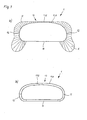
- Fig. 1 the cross section of a pipe 1 is shown in one embodiment.
- the tube 1 has a symmetrical to a plane of symmetry S-shaped cross-section.
- the width inside dimension B of the tube 1 is greater than the height inside dimension H.
- the tube 1 has a bottom wall 11, two side walls 12 and a top wall 13.
- the top wall 13 has a first area 131 and a second area 132.
- the first region 131 and the second region 132 are connected to each other and have different geometries.
- the geometries are different insofar as the first region 131 has a relatively large radius of curvature R1 in relation to the inside height dimension H of the tube 1 and the second region 132 has a comparatively small radius of curvature R2 relative to the inside height dimension H of the tube 1.
- the second region 132 is adjoined by a third region 133, which is connected to the side wall 12 and has a radius of curvature R3 which approximately corresponds to the radius of curvature R1 of the first region 131. This results in a largely trapezoidal cross-section the ceiling wall 13.
- the first radius of curvature R1 and the third radius of curvature R3 are approximately 7 times the inside height dimension H of the tube 1.
- the radius of curvature R2 corresponds approximately to the inside height dimension H of the tube 1.
- these dimensions can only be seen by way of example.
- other radii of curvature or straightness of the first region 131 and / or the third region 133 without radii of curvature R1, R3 are also encompassed by the invention.
- the largely trapezoidal design of the cross section of the top wall 13 supports the static stability of the tube 1.
- the side wall 12 has a radius of curvature R5, resulting in a good flow cross-section.
- a straight side wall 12 without radius of curvature R5 is also encompassed by the invention.
- the bottom wall 11 is straight in this embodiment, so that the tube is just placed on a floor or a ceiling.
- Fig. 2 shows the cross section of the tube 1 from Fig. 1 in a further embodiment.
- the bottom wall 11 also has a radius of curvature R4, which is relatively large in relation to the height inside dimension H of the tube 1 and here approximately corresponds to the radii R1, R3. Due to the slight curvature of the bottom wall 11 inside the tube has only two support points or lines and thus is more stable on a floor, as it is suitable by this embodiment, to compensate for any unevenness in the screed. Due to the only slight curvature of the flow cross-section of the tube 1 is not significantly reduced at the same time.
- Fig. 3 the cross section of the tube 1 is shown in a further embodiment.
- the tube 1 has wave crests 101 and wave troughs 102 on the outside.
- an inner tube 103 is arranged with a flat, smooth inner surface which is connected to the troughs 102.
- the tube 1 and the inner tube 103 made of a thermoplastic material which is extruded, preferably made of polyethylene or polypropylene.
- the tube 1 consists of a metal corrugated tube, preferably made of stainless steel, copper, aluminum or brass, in which an inner tube 103 made of a thermoplastic extrusionsrecten plastic or metal foil, for example, aluminum or stainless steel, inserted, in particular glued or welded.
- Fig. 4 represents the cross section of the tube 1 in a further embodiment.
- the installation of the tube 1 in a floor 5 is shown in a section.
- the Tube 1 rests on the screed 2.
- a thermal insulation 3 is arranged on both sides of the tube 1.
- Cavities between the thermal insulation 3 and the tube 1 are filled with a material 4. If the pipe 1 and the thermal insulation 3 are then covered with a further screed layer, the material 4 ensures that no cavities form under the screed and the screed does not crack.
- a material 4 for example, a perlite bed or a heat-insulating material is used. Due to the trapezoidal configuration of the top wall of the tube 1 of the resulting, to be filled with the material 4 cavity is kept relatively small.
- the cavity has a simple geometry, so that the material to be introduced 4 is easily cut to size, for example, by inserting a wedge shape. This facilitates the installation of the pipe 1 in the floor. 5
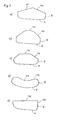
- the tube cross sections each have a bottom wall 11, side connections 12 and as a top wall a first region 131 and a second region 132.
- the first region 131 and the second region 132 are formed as straight lines and inclined to each other so as to form a roof-shaped cross section.
- the roof-shaped cross section has in Fig. 5a in the shape of a gable roof, in Fig. 5c the shape of a hipped roof and in Fig. 5e and 5f the shape of a pent roof.
- the first region 131 is formed as a straight line and the second region 132 is curved.
- both the first region 131 and the second region 132 are curved.
- the second region 132 has a negative radius of curvature, that is, it is curved inwards.
- Fig. 5g For example, both the first region 131 and the second region 132 are curved inward.
- Fig. 5h shows the tube Fig. 5g as a stacked arrangement.
- Fig. 6 shows different pipe cross sections with different wall thicknesses.
- Fig. 6a a section of the top wall 13 of a pipe is shown.
- the height of the wall in the first region 131 is greater than in the second region 132
- Fig. 6b is the pipe according to Fig. 1 shown.
- the wall is thickened.
- Fig. 6c shows a cross section of the tube 1 in a further embodiment.
- the height of the wall is greater than in the second region 132 and in the region of the side connections 12.
- the height of the wall is smaller than in the second region 132 and in the region of the side walls 12.
- Fig. 6d shows a tube 1 with a first Area 131, side connections 12 and a bottom wall 11.
- the height of the wall of the tube 1 is greater in the first region 131 than in the region of the side connections 12.
- the height of the wall is smaller than in the region of the side walls 12th
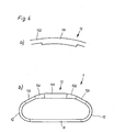
- Fig. 7 shows the cross section of the tube 11 in a further embodiment with a bottom wall 11, side connections 12 and a top wall 13.
- the curvature of the top wall 13 extends curvature continuous.
- the top wall has a plurality of regions 131, 132, ..., each having different radii of curvature.
- Fig. 7b shows the cross section of the tube 1
- Fig. 7a the cross section of the tube 1 in an enlarged view with a representation of the curvature K
- the radii given are merely exemplary, so that between the individual radii an indefinite number of other radii is.
- the side connection 12 has a plurality of regions with different radii of curvature, so that from the bottom wall 11 to the top wall 13 and within the top wall 13 a curvature continuous course is given.
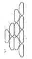
- Fig. 8 are different tubes 1 off Fig. 1 shown. From this is the good stackability of pipes 1 according to Fig. 1 recognizable due to the cross section.
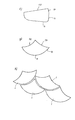
- Fig. 9 shows a section of the tube 1 with crests 101, between which a wave trough 102 is arranged. Furthermore, the tube 1 has an inner tube 103.
- the wall thickness of the wave peaks 101 and troughs 102 preferably varies between about 0.2 and 1.0 mm, in particular about 0.5 mm to 0.9 mm, preferably about 0.6 and 0.85 mm, wherein the thinnest point in the region of the wave crest 101 and the thickest point in the region of the wave trough 102 is formed.
- Fig. 9a shows an enlarged view of two peaks 101 and Fig. 9b an enlarged view of a wave peak 102.
Landscapes
- Engineering & Computer Science (AREA)
- General Engineering & Computer Science (AREA)
- Mechanical Engineering (AREA)
- Physics & Mathematics (AREA)
- Thermal Sciences (AREA)
- Chemical & Material Sciences (AREA)
- Combustion & Propulsion (AREA)
- Rigid Pipes And Flexible Pipes (AREA)
Priority Applications (1)
| Application Number | Priority Date | Filing Date | Title |
|---|---|---|---|
| PL11007561T PL2431642T3 (pl) | 2010-09-16 | 2011-09-16 | Rura do przewodzenia płynu |
Applications Claiming Priority (1)
| Application Number | Priority Date | Filing Date | Title |
|---|---|---|---|
| DE202010012660U DE202010012660U1 (de) | 2010-09-16 | 2010-09-16 | Rohr zur Leitung eines Fluids |
Publications (3)
| Publication Number | Publication Date |
|---|---|
| EP2431642A2 true EP2431642A2 (fr) | 2012-03-21 |
| EP2431642A3 EP2431642A3 (fr) | 2016-10-19 |
| EP2431642B1 EP2431642B1 (fr) | 2020-02-26 |
Family
ID=43299554
Family Applications (1)
| Application Number | Title | Priority Date | Filing Date |
|---|---|---|---|
| EP11007561.1A Active EP2431642B1 (fr) | 2010-09-16 | 2011-09-16 | Tuyau de guidage d'un fluide |
Country Status (5)
| Country | Link |
|---|---|
| EP (1) | EP2431642B1 (fr) |
| DE (1) | DE202010012660U1 (fr) |
| ES (1) | ES2791763T3 (fr) |
| LT (1) | LT2431642T (fr) |
| PL (1) | PL2431642T3 (fr) |
Cited By (6)
| Publication number | Priority date | Publication date | Assignee | Title |
|---|---|---|---|---|
| EP3667143A1 (fr) | 2018-12-12 | 2020-06-17 | Ralph Peter Hegler | Tube de raccordement pour la technique de climatisation et d'aération |
| EP3667144A1 (fr) | 2018-12-12 | 2020-06-17 | Ralph Peter Hegler | Ensemble pour établir un raccord entre deux tubes composite pour la climatisation et la ventilation. |
| US11015744B2 (en) * | 2017-03-17 | 2021-05-25 | Schlemmer Holding GmbH | Composite tube |
| DE102022113941A1 (de) | 2022-06-02 | 2023-12-07 | Stiebel Eltron Gmbh & Co. Kg | Luftverteilungssystem |
| EP4656921A1 (fr) * | 2024-05-27 | 2025-12-03 | UNICOR GmbH | Tuyau ondulé en matière plastique pour la technique de climatisation et/ou de ventilation |
| WO2025247904A1 (fr) * | 2024-05-27 | 2025-12-04 | Unicor Gmbh | Tube en plastique ondulé pour technologie de climatisation et/ou de ventilation |
Families Citing this family (4)
| Publication number | Priority date | Publication date | Assignee | Title |
|---|---|---|---|---|
| DE102011118939A1 (de) * | 2011-11-21 | 2013-05-23 | Westfalia Metallschlauchtechnik Gmbh & Co. Kg | Ausführungsform streckbarer Metallschläuche und zugehöriges Werkzeugelement |
| DE102017105265A1 (de) | 2017-03-13 | 2018-09-13 | Stiebel Eltron Gmbh & Co. Kg | Wärmeübertragerrohr und Wärmeübertrager-Baugruppe |
| CN107676896B (zh) * | 2017-10-09 | 2023-05-16 | 浙江星光电科智能家居科技有限公司 | 一种真空送气制冷制热管路结构 |
| CH718744A2 (de) | 2021-06-16 | 2022-12-30 | Zehnder Group Int Ag | Rohr zum Transport eines wärmetragenden Fluides. |
Citations (4)
| Publication number | Priority date | Publication date | Assignee | Title |
|---|---|---|---|---|
| DE2752622A1 (de) | 1977-11-25 | 1979-05-31 | Roehl Georg | Luftfuehrungskanal fuer abluftsysteme |
| DE102008013013A1 (de) | 2007-03-21 | 2008-11-20 | Frank & Krah Wickelrohr Gmbh | Wärmeübertragendes Rohr |
| EP2019242A2 (fr) | 2007-07-23 | 2009-01-28 | FRÄNKISCHE ROHRWERKE GEBR. KIRCHNER GmbH & Co KG | Tuyau et association de deux tuyaux de ce type |
| EP2131114A1 (fr) | 2008-06-03 | 2009-12-09 | Centrotherm Systemtechnik GmbH | Tube ondulé en plastique doté d'une section transversale aplatie |
Family Cites Families (8)
| Publication number | Priority date | Publication date | Assignee | Title |
|---|---|---|---|---|
| GB191227782A (en) * | 1912-12-03 | 1913-06-12 | Jean Gallay | Improved Radiator for Automobiles and the like. |
| DE1775675A1 (de) * | 1968-09-09 | 1971-09-09 | Juergen Reichardt | Unterflurrohrleitung aus Kunststoff |
| DE2918058A1 (de) * | 1979-05-04 | 1980-11-13 | Roehl Georg | Rohr fuer eine ent- oder belueftungsleitung |
| DE4122388A1 (de) * | 1991-07-06 | 1993-01-14 | Weth Nikolaus Dipl Kaufm | Schlauch oder rohr fuer begasungs- oder belueftungszwecke |
| JP3099185B2 (ja) * | 1997-05-26 | 2000-10-16 | 東拓工業株式会社 | 合成樹脂管体 |
| FI20021198A7 (fi) * | 2002-06-19 | 2003-12-20 | Uponor Innovation Ab | Ilmanvaihtokanava ja sovitelma ilmanvaihtokanavan yhteydessä |
| US7785514B2 (en) * | 2006-05-18 | 2010-08-31 | Mccarthy Peter T | Snorkels, flexible tubes, mouthpieces and methods |
| CA2653137C (fr) * | 2009-02-09 | 2016-01-12 | Manfred A. A. Lupke | Profile de conduit non circulaire |
-
2010
- 2010-09-16 DE DE202010012660U patent/DE202010012660U1/de not_active Expired - Lifetime
-
2011
- 2011-09-16 EP EP11007561.1A patent/EP2431642B1/fr active Active
- 2011-09-16 ES ES11007561T patent/ES2791763T3/es active Active
- 2011-09-16 LT LTEP11007561.1T patent/LT2431642T/lt unknown
- 2011-09-16 PL PL11007561T patent/PL2431642T3/pl unknown
Patent Citations (5)
| Publication number | Priority date | Publication date | Assignee | Title |
|---|---|---|---|---|
| DE2752622A1 (de) | 1977-11-25 | 1979-05-31 | Roehl Georg | Luftfuehrungskanal fuer abluftsysteme |
| DE102008013013A1 (de) | 2007-03-21 | 2008-11-20 | Frank & Krah Wickelrohr Gmbh | Wärmeübertragendes Rohr |
| EP2019242A2 (fr) | 2007-07-23 | 2009-01-28 | FRÄNKISCHE ROHRWERKE GEBR. KIRCHNER GmbH & Co KG | Tuyau et association de deux tuyaux de ce type |
| EP2131114A1 (fr) | 2008-06-03 | 2009-12-09 | Centrotherm Systemtechnik GmbH | Tube ondulé en plastique doté d'une section transversale aplatie |
| EP2131114B1 (fr) | 2008-06-03 | 2010-07-28 | Centrotherm Systemtechnik GmbH | Tube ondulé en plastique doté d'une section transversale aplatie |
Cited By (9)
| Publication number | Priority date | Publication date | Assignee | Title |
|---|---|---|---|---|
| US11015744B2 (en) * | 2017-03-17 | 2021-05-25 | Schlemmer Holding GmbH | Composite tube |
| EP3667143A1 (fr) | 2018-12-12 | 2020-06-17 | Ralph Peter Hegler | Tube de raccordement pour la technique de climatisation et d'aération |
| EP3667144A1 (fr) | 2018-12-12 | 2020-06-17 | Ralph Peter Hegler | Ensemble pour établir un raccord entre deux tubes composite pour la climatisation et la ventilation. |
| DE102018221506A1 (de) | 2018-12-12 | 2020-06-18 | Ralph Peter Hegler | Bausatz zur Herstellung einer Verbindung zwischen zwei Verbundrohren für Klima- und Lüftungstechnik |
| DE102018221508A1 (de) | 2018-12-12 | 2020-06-18 | Ralph Peter Hegler | Verbundrohr für Klima- und Lüftungstechnik |
| DE102022113941A1 (de) | 2022-06-02 | 2023-12-07 | Stiebel Eltron Gmbh & Co. Kg | Luftverteilungssystem |
| EP4656921A1 (fr) * | 2024-05-27 | 2025-12-03 | UNICOR GmbH | Tuyau ondulé en matière plastique pour la technique de climatisation et/ou de ventilation |
| EP4656922A1 (fr) * | 2024-05-27 | 2025-12-03 | UNICOR GmbH | Tuyau ondulé en matière plastique pour la technique de climatisation et/ou de ventilation |
| WO2025247904A1 (fr) * | 2024-05-27 | 2025-12-04 | Unicor Gmbh | Tube en plastique ondulé pour technologie de climatisation et/ou de ventilation |
Also Published As
| Publication number | Publication date |
|---|---|
| EP2431642B1 (fr) | 2020-02-26 |
| PL2431642T3 (pl) | 2020-07-27 |
| ES2791763T3 (es) | 2020-11-05 |
| EP2431642A3 (fr) | 2016-10-19 |
| LT2431642T (lt) | 2020-05-11 |
| DE202010012660U1 (de) | 2010-12-02 |
Similar Documents
| Publication | Publication Date | Title |
|---|---|---|
| EP2431642B1 (fr) | Tuyau de guidage d'un fluide | |
| DE2728971C3 (de) | Einsatz für ein Wärmetauscherrohr | |
| DE102017012049B4 (de) | Erdwärmesonde in Form einer Koaxialsonde mit Doppelrohr-Schlauch und Herstellungsverfahren hierfür | |
| DE102008013013A1 (de) | Wärmeübertragendes Rohr | |
| DE3124048A1 (de) | Heizkoerper fuer warmwasser-flaechenbeheizung, insbesondere fuer boden- oder wandbeheizung | |
| CH666538A5 (de) | Waermeuebertrager mit mehreren parallelen rohren und auf diesen angebrachten rippen. | |
| DE3034888A1 (de) | Aus einem flexiblen oder steifen kunststoff bestehendes rohr zum transport eines waermetraegers | |
| DE2837802A1 (de) | Mit grosser uebertragungsflaeche versehene koerper, welche bei der herstellung von waermeaustauschapparaturen angewendet werden | |
| DE3126618A1 (de) | Vorrichtung, bei welcher waerme durch hohlfaeden uebertragen wird | |
| WO2011128051A1 (fr) | Système de tuyaux pour installation intérieure et son utilisation | |
| DE102008002186B4 (de) | Kunststoffwellrohr mit einem abgeflachten Querschnitt | |
| EP0537319B1 (fr) | Tuyau en plastique | |
| EP1724508B1 (fr) | Tuyau | |
| EP2829833B1 (fr) | Dispositif de dissipation de la chaleur d'eaux usées | |
| DE2531907A1 (de) | System zur nutzung der sonnenenergie | |
| EP0601443A1 (fr) | Collecteur solaire avec conduites de distribution internes | |
| DE202005005056U1 (de) | Kunststoff-Rohr für Klima- und Lüftungs-Technik | |
| DE202014101774U1 (de) | Flüssigkeitsverteileinrichtung | |
| EP2801766A1 (fr) | Collecteur solaire pour le chauffage d'un caloporteur | |
| DE102010006371B4 (de) | Wärmetauscher | |
| DE202006011151U1 (de) | Plattenförmige Vorrichtung zur Aufnahme von Leitungen | |
| DE2821090A1 (de) | Absorberbauteil fuer einen sonnenkollektor | |
| DE2542934A1 (de) | Fussboden-warmluftheizung | |
| DE102010015851A1 (de) | Solarheizung | |
| DE2532174A1 (de) | System zur nutzung der sonnenenergie |
Legal Events
| Date | Code | Title | Description |
|---|---|---|---|
| PUAI | Public reference made under article 153(3) epc to a published international application that has entered the european phase |
Free format text: ORIGINAL CODE: 0009012 |
|
| AK | Designated contracting states |
Kind code of ref document: A2 Designated state(s): AL AT BE BG CH CY CZ DE DK EE ES FI FR GB GR HR HU IE IS IT LI LT LU LV MC MK MT NL NO PL PT RO RS SE SI SK SM TR |
|
| AX | Request for extension of the european patent |
Extension state: BA ME |
|
| RAP1 | Party data changed (applicant data changed or rights of an application transferred) |
Owner name: FRAENKISCHE INDUSTRIAL PIPES GMBH & CO. KG |
|
| RAP1 | Party data changed (applicant data changed or rights of an application transferred) |
Owner name: STIEBEL ELTRON GMBH & CO. KG Owner name: FRAENKISCHE INDUSTRIAL PIPES GMBH & CO. KG |
|
| PUAL | Search report despatched |
Free format text: ORIGINAL CODE: 0009013 |
|
| AK | Designated contracting states |
Kind code of ref document: A3 Designated state(s): AL AT BE BG CH CY CZ DE DK EE ES FI FR GB GR HR HU IE IS IT LI LT LU LV MC MK MT NL NO PL PT RO RS SE SI SK SM TR |
|
| AX | Request for extension of the european patent |
Extension state: BA ME |
|
| RIC1 | Information provided on ipc code assigned before grant |
Ipc: F24D 3/14 20060101ALI20160914BHEP Ipc: F16L 11/11 20060101AFI20160914BHEP Ipc: F16L 9/00 20060101ALI20160914BHEP Ipc: F16L 11/15 20060101ALI20160914BHEP Ipc: B29C 47/00 20060101ALN20160914BHEP Ipc: F16L 9/06 20060101ALI20160914BHEP Ipc: B29C 47/12 20060101ALN20160914BHEP Ipc: F16L 11/12 20060101ALI20160914BHEP |
|
| STAA | Information on the status of an ep patent application or granted ep patent |
Free format text: STATUS: REQUEST FOR EXAMINATION WAS MADE |
|
| 17P | Request for examination filed |
Effective date: 20170419 |
|
| RBV | Designated contracting states (corrected) |
Designated state(s): AL AT BE BG CH CY CZ DE DK EE ES FI FR GB GR HR HU IE IS IT LI LT LU LV MC MK MT NL NO PL PT RO RS SE SI SK SM TR |
|
| STAA | Information on the status of an ep patent application or granted ep patent |
Free format text: STATUS: EXAMINATION IS IN PROGRESS |
|
| 17Q | First examination report despatched |
Effective date: 20171109 |
|
| TPAC | Observations filed by third parties |
Free format text: ORIGINAL CODE: EPIDOSNTIPA |
|
| REG | Reference to a national code |
Ref country code: DE Ref legal event code: R079 Ref document number: 502011016487 Country of ref document: DE Free format text: PREVIOUS MAIN CLASS: F16L0009000000 Ipc: F16L0011110000 |
|
| RIC1 | Information provided on ipc code assigned before grant |
Ipc: B29C 48/09 20190101ALN20190729BHEP Ipc: F16L 9/00 20060101ALI20190729BHEP Ipc: F16L 9/06 20060101ALI20190729BHEP Ipc: B29C 48/13 20190101ALN20190729BHEP Ipc: F16L 11/11 20060101AFI20190729BHEP Ipc: F24D 3/14 20060101ALI20190729BHEP Ipc: F16L 11/15 20060101ALI20190729BHEP Ipc: F16L 11/12 20060101ALI20190729BHEP |
|
| GRAP | Despatch of communication of intention to grant a patent |
Free format text: ORIGINAL CODE: EPIDOSNIGR1 |
|
| STAA | Information on the status of an ep patent application or granted ep patent |
Free format text: STATUS: GRANT OF PATENT IS INTENDED |
|
| INTG | Intention to grant announced |
Effective date: 20190918 |
|
| GRAS | Grant fee paid |
Free format text: ORIGINAL CODE: EPIDOSNIGR3 |
|
| GRAA | (expected) grant |
Free format text: ORIGINAL CODE: 0009210 |
|
| STAA | Information on the status of an ep patent application or granted ep patent |
Free format text: STATUS: THE PATENT HAS BEEN GRANTED |
|
| AK | Designated contracting states |
Kind code of ref document: B1 Designated state(s): AL AT BE BG CH CY CZ DE DK EE ES FI FR GB GR HR HU IE IS IT LI LT LU LV MC MK MT NL NO PL PT RO RS SE SI SK SM TR |
|
| REG | Reference to a national code |
Ref country code: GB Ref legal event code: FG4D Free format text: NOT ENGLISH |
|
| REG | Reference to a national code |
Ref country code: CH Ref legal event code: EP |
|
| REG | Reference to a national code |
Ref country code: AT Ref legal event code: REF Ref document number: 1238045 Country of ref document: AT Kind code of ref document: T Effective date: 20200315 |
|
| REG | Reference to a national code |
Ref country code: IE Ref legal event code: FG4D Free format text: LANGUAGE OF EP DOCUMENT: GERMAN |
|
| REG | Reference to a national code |
Ref country code: DE Ref legal event code: R096 Ref document number: 502011016487 Country of ref document: DE |
|
| REG | Reference to a national code |
Ref country code: NL Ref legal event code: FP |
|
| REG | Reference to a national code |
Ref country code: EE Ref legal event code: FG4A Ref document number: E019236 Country of ref document: EE Effective date: 20200506 |
|
| PG25 | Lapsed in a contracting state [announced via postgrant information from national office to epo] |
Ref country code: FI Free format text: LAPSE BECAUSE OF FAILURE TO SUBMIT A TRANSLATION OF THE DESCRIPTION OR TO PAY THE FEE WITHIN THE PRESCRIBED TIME-LIMIT Effective date: 20200226 Ref country code: RS Free format text: LAPSE BECAUSE OF FAILURE TO SUBMIT A TRANSLATION OF THE DESCRIPTION OR TO PAY THE FEE WITHIN THE PRESCRIBED TIME-LIMIT Effective date: 20200226 Ref country code: NO Free format text: LAPSE BECAUSE OF FAILURE TO SUBMIT A TRANSLATION OF THE DESCRIPTION OR TO PAY THE FEE WITHIN THE PRESCRIBED TIME-LIMIT Effective date: 20200526 |
|
| PG25 | Lapsed in a contracting state [announced via postgrant information from national office to epo] |
Ref country code: IS Free format text: LAPSE BECAUSE OF FAILURE TO SUBMIT A TRANSLATION OF THE DESCRIPTION OR TO PAY THE FEE WITHIN THE PRESCRIBED TIME-LIMIT Effective date: 20200626 Ref country code: BG Free format text: LAPSE BECAUSE OF FAILURE TO SUBMIT A TRANSLATION OF THE DESCRIPTION OR TO PAY THE FEE WITHIN THE PRESCRIBED TIME-LIMIT Effective date: 20200526 Ref country code: SE Free format text: LAPSE BECAUSE OF FAILURE TO SUBMIT A TRANSLATION OF THE DESCRIPTION OR TO PAY THE FEE WITHIN THE PRESCRIBED TIME-LIMIT Effective date: 20200226 Ref country code: LV Free format text: LAPSE BECAUSE OF FAILURE TO SUBMIT A TRANSLATION OF THE DESCRIPTION OR TO PAY THE FEE WITHIN THE PRESCRIBED TIME-LIMIT Effective date: 20200226 Ref country code: GR Free format text: LAPSE BECAUSE OF FAILURE TO SUBMIT A TRANSLATION OF THE DESCRIPTION OR TO PAY THE FEE WITHIN THE PRESCRIBED TIME-LIMIT Effective date: 20200527 Ref country code: HR Free format text: LAPSE BECAUSE OF FAILURE TO SUBMIT A TRANSLATION OF THE DESCRIPTION OR TO PAY THE FEE WITHIN THE PRESCRIBED TIME-LIMIT Effective date: 20200226 |
|
| PG25 | Lapsed in a contracting state [announced via postgrant information from national office to epo] |
Ref country code: PT Free format text: LAPSE BECAUSE OF FAILURE TO SUBMIT A TRANSLATION OF THE DESCRIPTION OR TO PAY THE FEE WITHIN THE PRESCRIBED TIME-LIMIT Effective date: 20200719 Ref country code: DK Free format text: LAPSE BECAUSE OF FAILURE TO SUBMIT A TRANSLATION OF THE DESCRIPTION OR TO PAY THE FEE WITHIN THE PRESCRIBED TIME-LIMIT Effective date: 20200226 Ref country code: SM Free format text: LAPSE BECAUSE OF FAILURE TO SUBMIT A TRANSLATION OF THE DESCRIPTION OR TO PAY THE FEE WITHIN THE PRESCRIBED TIME-LIMIT Effective date: 20200226 Ref country code: RO Free format text: LAPSE BECAUSE OF FAILURE TO SUBMIT A TRANSLATION OF THE DESCRIPTION OR TO PAY THE FEE WITHIN THE PRESCRIBED TIME-LIMIT Effective date: 20200226 Ref country code: SK Free format text: LAPSE BECAUSE OF FAILURE TO SUBMIT A TRANSLATION OF THE DESCRIPTION OR TO PAY THE FEE WITHIN THE PRESCRIBED TIME-LIMIT Effective date: 20200226 |
|
| REG | Reference to a national code |
Ref country code: ES Ref legal event code: FG2A Ref document number: 2791763 Country of ref document: ES Kind code of ref document: T3 Effective date: 20201105 |
|
| REG | Reference to a national code |
Ref country code: DE Ref legal event code: R097 Ref document number: 502011016487 Country of ref document: DE |
|
| PLBE | No opposition filed within time limit |
Free format text: ORIGINAL CODE: 0009261 |
|
| STAA | Information on the status of an ep patent application or granted ep patent |
Free format text: STATUS: NO OPPOSITION FILED WITHIN TIME LIMIT |
|
| 26N | No opposition filed |
Effective date: 20201127 |
|
| PG25 | Lapsed in a contracting state [announced via postgrant information from national office to epo] |
Ref country code: SI Free format text: LAPSE BECAUSE OF FAILURE TO SUBMIT A TRANSLATION OF THE DESCRIPTION OR TO PAY THE FEE WITHIN THE PRESCRIBED TIME-LIMIT Effective date: 20200226 |
|
| PG25 | Lapsed in a contracting state [announced via postgrant information from national office to epo] |
Ref country code: MC Free format text: LAPSE BECAUSE OF FAILURE TO SUBMIT A TRANSLATION OF THE DESCRIPTION OR TO PAY THE FEE WITHIN THE PRESCRIBED TIME-LIMIT Effective date: 20200226 |
|
| PG25 | Lapsed in a contracting state [announced via postgrant information from national office to epo] |
Ref country code: IE Free format text: LAPSE BECAUSE OF NON-PAYMENT OF DUE FEES Effective date: 20200916 |
|
| PG25 | Lapsed in a contracting state [announced via postgrant information from national office to epo] |
Ref country code: TR Free format text: LAPSE BECAUSE OF FAILURE TO SUBMIT A TRANSLATION OF THE DESCRIPTION OR TO PAY THE FEE WITHIN THE PRESCRIBED TIME-LIMIT Effective date: 20200226 Ref country code: MT Free format text: LAPSE BECAUSE OF FAILURE TO SUBMIT A TRANSLATION OF THE DESCRIPTION OR TO PAY THE FEE WITHIN THE PRESCRIBED TIME-LIMIT Effective date: 20200226 Ref country code: CY Free format text: LAPSE BECAUSE OF FAILURE TO SUBMIT A TRANSLATION OF THE DESCRIPTION OR TO PAY THE FEE WITHIN THE PRESCRIBED TIME-LIMIT Effective date: 20200226 |
|
| PG25 | Lapsed in a contracting state [announced via postgrant information from national office to epo] |
Ref country code: MK Free format text: LAPSE BECAUSE OF FAILURE TO SUBMIT A TRANSLATION OF THE DESCRIPTION OR TO PAY THE FEE WITHIN THE PRESCRIBED TIME-LIMIT Effective date: 20200226 Ref country code: AL Free format text: LAPSE BECAUSE OF FAILURE TO SUBMIT A TRANSLATION OF THE DESCRIPTION OR TO PAY THE FEE WITHIN THE PRESCRIBED TIME-LIMIT Effective date: 20200226 |
|
| P01 | Opt-out of the competence of the unified patent court (upc) registered |
Effective date: 20230519 |
|
| P02 | Opt-out of the competence of the unified patent court (upc) changed |
Effective date: 20230526 |
|
| PGFP | Annual fee paid to national office [announced via postgrant information from national office to epo] |
Ref country code: NL Payment date: 20230920 Year of fee payment: 13 Ref country code: LU Payment date: 20230918 Year of fee payment: 13 Ref country code: AT Payment date: 20230915 Year of fee payment: 13 |
|
| PGFP | Annual fee paid to national office [announced via postgrant information from national office to epo] |
Ref country code: FR Payment date: 20230918 Year of fee payment: 13 |
|
| PGFP | Annual fee paid to national office [announced via postgrant information from national office to epo] |
Ref country code: ES Payment date: 20231019 Year of fee payment: 13 |
|
| PGFP | Annual fee paid to national office [announced via postgrant information from national office to epo] |
Ref country code: CH Payment date: 20231001 Year of fee payment: 13 |
|
| PGFP | Annual fee paid to national office [announced via postgrant information from national office to epo] |
Ref country code: CZ Payment date: 20250314 Year of fee payment: 14 Ref country code: PL Payment date: 20250314 Year of fee payment: 14 |
|
| REG | Reference to a national code |
Ref country code: CH Ref legal event code: PL |
|
| REG | Reference to a national code |
Ref country code: NL Ref legal event code: MM Effective date: 20241001 |
|
| REG | Reference to a national code |
Ref country code: AT Ref legal event code: MM01 Ref document number: 1238045 Country of ref document: AT Kind code of ref document: T Effective date: 20240916 |
|
| PG25 | Lapsed in a contracting state [announced via postgrant information from national office to epo] |
Ref country code: LU Free format text: LAPSE BECAUSE OF NON-PAYMENT OF DUE FEES Effective date: 20240916 |
|
| GBPC | Gb: european patent ceased through non-payment of renewal fee |
Effective date: 20240916 |
|
| REG | Reference to a national code |
Ref country code: GB Ref legal event code: S28 Free format text: APPLICATION FILED |
|
| PG25 | Lapsed in a contracting state [announced via postgrant information from national office to epo] |
Ref country code: NL Free format text: LAPSE BECAUSE OF NON-PAYMENT OF DUE FEES Effective date: 20241001 |
|
| PG25 | Lapsed in a contracting state [announced via postgrant information from national office to epo] |
Ref country code: GB Free format text: LAPSE BECAUSE OF NON-PAYMENT OF DUE FEES Effective date: 20240916 |
|
| PG25 | Lapsed in a contracting state [announced via postgrant information from national office to epo] |
Ref country code: FR Free format text: LAPSE BECAUSE OF NON-PAYMENT OF DUE FEES Effective date: 20240930 |
|
| PG25 | Lapsed in a contracting state [announced via postgrant information from national office to epo] |
Ref country code: CH Free format text: LAPSE BECAUSE OF NON-PAYMENT OF DUE FEES Effective date: 20240930 |
|
| PG25 | Lapsed in a contracting state [announced via postgrant information from national office to epo] |
Ref country code: AT Free format text: LAPSE BECAUSE OF NON-PAYMENT OF DUE FEES Effective date: 20240916 |
|
| REG | Reference to a national code |
Ref country code: GB Ref legal event code: S28 Free format text: RESTORATION ALLOWED Effective date: 20250717 |
|
| PG25 | Lapsed in a contracting state [announced via postgrant information from national office to epo] |
Ref country code: GB Free format text: LAPSE BECAUSE OF NON-PAYMENT OF DUE FEES Effective date: 20240916 |
|
| PGFP | Annual fee paid to national office [announced via postgrant information from national office to epo] |
Ref country code: BE Payment date: 20250919 Year of fee payment: 15 Ref country code: GB Payment date: 20250923 Year of fee payment: 15 |
|
| PGRI | Patent reinstated in contracting state [announced from national office to epo] |
Ref country code: GB Effective date: 20250717 |
|
| PGFP | Annual fee paid to national office [announced via postgrant information from national office to epo] |
Ref country code: EE Payment date: 20250922 Year of fee payment: 15 |
|
| REG | Reference to a national code |
Ref country code: ES Ref legal event code: FD2A Effective date: 20251030 |
|
| PGFP | Annual fee paid to national office [announced via postgrant information from national office to epo] |
Ref country code: DE Payment date: 20251007 Year of fee payment: 15 |
|
| PGFP | Annual fee paid to national office [announced via postgrant information from national office to epo] |
Ref country code: LT Payment date: 20251006 Year of fee payment: 15 |
|
| PGFP | Annual fee paid to national office [announced via postgrant information from national office to epo] |
Ref country code: IT Payment date: 20250930 Year of fee payment: 15 |
|
| PG25 | Lapsed in a contracting state [announced via postgrant information from national office to epo] |
Ref country code: ES Free format text: LAPSE BECAUSE OF NON-PAYMENT OF DUE FEES Effective date: 20240917 |
|
| PG25 | Lapsed in a contracting state [announced via postgrant information from national office to epo] |
Ref country code: CZ Free format text: LAPSE BECAUSE OF NON-PAYMENT OF DUE FEES Effective date: 20250916 |