EP2131167B1 - Dispositif d'établissement de l'état de chargement de véhicules - Google Patents
Dispositif d'établissement de l'état de chargement de véhicules Download PDFInfo
- Publication number
- EP2131167B1 EP2131167B1 EP20090007409 EP09007409A EP2131167B1 EP 2131167 B1 EP2131167 B1 EP 2131167B1 EP 20090007409 EP20090007409 EP 20090007409 EP 09007409 A EP09007409 A EP 09007409A EP 2131167 B1 EP2131167 B1 EP 2131167B1
- Authority
- EP
- European Patent Office
- Prior art keywords
- reference plate
- laser beam
- distance
- bogie
- vehicle
- Prior art date
- Legal status (The legal status is an assumption and is not a legal conclusion. Google has not performed a legal analysis and makes no representation as to the accuracy of the status listed.)
- Active
Links
- 238000005259 measurement Methods 0.000 claims description 8
- 239000003990 capacitor Substances 0.000 claims description 3
- 238000005286 illumination Methods 0.000 claims 1
- 238000004891 communication Methods 0.000 description 8
- 239000000725 suspension Substances 0.000 description 5
- 230000006835 compression Effects 0.000 description 3
- 238000007906 compression Methods 0.000 description 3
- 238000009420 retrofitting Methods 0.000 description 3
- 230000001419 dependent effect Effects 0.000 description 2
- 238000010586 diagram Methods 0.000 description 2
- 238000012423 maintenance Methods 0.000 description 2
- 241000196324 Embryophyta Species 0.000 description 1
- 230000004888 barrier function Effects 0.000 description 1
- 238000005452 bending Methods 0.000 description 1
- 230000000903 blocking effect Effects 0.000 description 1
- 238000006243 chemical reaction Methods 0.000 description 1
- 238000010276 construction Methods 0.000 description 1
- 238000013461 design Methods 0.000 description 1
- 230000005611 electricity Effects 0.000 description 1
- 238000005516 engineering process Methods 0.000 description 1
- 230000010354 integration Effects 0.000 description 1
- 238000005461 lubrication Methods 0.000 description 1
- 238000000034 method Methods 0.000 description 1
- 230000000737 periodic effect Effects 0.000 description 1
- 238000010992 reflux Methods 0.000 description 1
- 230000001105 regulatory effect Effects 0.000 description 1
- 238000005096 rolling process Methods 0.000 description 1
- 238000004904 shortening Methods 0.000 description 1
- 238000012360 testing method Methods 0.000 description 1
Images

Classifications
-
- G—PHYSICS
- G01—MEASURING; TESTING
- G01G—WEIGHING
- G01G23/00—Auxiliary devices for weighing apparatus
- G01G23/007—Integrated arrangements for generating electrical power, e.g. solar cells
-
- G—PHYSICS
- G01—MEASURING; TESTING
- G01G—WEIGHING
- G01G19/00—Weighing apparatus or methods adapted for special purposes not provided for in the preceding groups
- G01G19/02—Weighing apparatus or methods adapted for special purposes not provided for in the preceding groups for weighing wheeled or rolling bodies, e.g. vehicles
- G01G19/04—Weighing apparatus or methods adapted for special purposes not provided for in the preceding groups for weighing wheeled or rolling bodies, e.g. vehicles for weighing railway vehicles
- G01G19/042—Weighing apparatus or methods adapted for special purposes not provided for in the preceding groups for weighing wheeled or rolling bodies, e.g. vehicles for weighing railway vehicles having electrical weight-sensitive devices
-
- G—PHYSICS
- G01—MEASURING; TESTING
- G01G—WEIGHING
- G01G19/00—Weighing apparatus or methods adapted for special purposes not provided for in the preceding groups
- G01G19/08—Weighing apparatus or methods adapted for special purposes not provided for in the preceding groups for incorporation in vehicles
- G01G19/12—Weighing apparatus or methods adapted for special purposes not provided for in the preceding groups for incorporation in vehicles having electrical weight-sensitive devices
-
- G—PHYSICS
- G01—MEASURING; TESTING
- G01G—WEIGHING
- G01G23/00—Auxiliary devices for weighing apparatus
-
- G—PHYSICS
- G01—MEASURING; TESTING
- G01G—WEIGHING
- G01G23/00—Auxiliary devices for weighing apparatus
- G01G23/18—Indicating devices, e.g. for remote indication; Recording devices; Scales, e.g. graduated
- G01G23/36—Indicating the weight by electrical means, e.g. using photoelectric cells
- G01G23/37—Indicating the weight by electrical means, e.g. using photoelectric cells involving digital counting
- G01G23/3728—Indicating the weight by electrical means, e.g. using photoelectric cells involving digital counting with wireless means
- G01G23/3735—Indicating the weight by electrical means, e.g. using photoelectric cells involving digital counting with wireless means using a digital network
- G01G23/3742—Indicating the weight by electrical means, e.g. using photoelectric cells involving digital counting with wireless means using a digital network using a mobile telephone network
-
- G—PHYSICS
- G01—MEASURING; TESTING
- G01S—RADIO DIRECTION-FINDING; RADIO NAVIGATION; DETERMINING DISTANCE OR VELOCITY BY USE OF RADIO WAVES; LOCATING OR PRESENCE-DETECTING BY USE OF THE REFLECTION OR RERADIATION OF RADIO WAVES; ANALOGOUS ARRANGEMENTS USING OTHER WAVES
- G01S17/00—Systems using the reflection or reradiation of electromagnetic waves other than radio waves, e.g. lidar systems
- G01S17/88—Lidar systems specially adapted for specific applications
-
- G—PHYSICS
- G01—MEASURING; TESTING
- G01S—RADIO DIRECTION-FINDING; RADIO NAVIGATION; DETERMINING DISTANCE OR VELOCITY BY USE OF RADIO WAVES; LOCATING OR PRESENCE-DETECTING BY USE OF THE REFLECTION OR RERADIATION OF RADIO WAVES; ANALOGOUS ARRANGEMENTS USING OTHER WAVES
- G01S7/00—Details of systems according to groups G01S13/00, G01S15/00, G01S17/00
- G01S7/003—Transmission of data between radar, sonar or lidar systems and remote stations
Definitions
- the invention relates to a device for determining the state of charge of vehicles, in particular railway vehicles.
- the previously known load sensors for freight cars do not meet the current requirements in rough practice. Accordingly, the load sensor should be maintenance-free and be viable in the harsh environment of transport and in particular the railroad. Furthermore, it is necessary that the device for determining the state of charge for various types of wagons are used, such. Waggons for bulk goods and wagons for car transport etc.
- the wheel bearings are arranged in a known manner from the outside accessible on the ends of the axles and are slightly ahead of the wheels, so that the wheel bearing, whose housing does not rotate with the wheel, is available as a reference point.
- the distance measuring device comprises a laser beam source fixed to the vehicle body and a laser beam sensor, as well as a reference plate fixed to the wheel bearing and illuminated by the laser beam source, the travel time of the laser beam being used to calculate the distance by means of a computing unit.
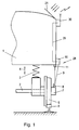
- FIG. 1 shows a schematic partial cross-section through a railway car, the railway elements are only indicated.
- FIG. 2 shows schematically in oblique view the arrangement on a bogie with two wheel axles,
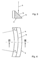
- FIG. 3 an enlarged view of the reference plate in section and
- FIG. 4 shows a plan view of this reference plate.
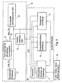
- FIG. 5 shows in the block diagram the integration of the device in a messaging system.
- FIG. 1 shows schematically the application of the device to a freight car.
- the vehicle body 1 serves to receive the load and is sprung relative to the axles 2 of the vehicle, which is indicated by the compression spring 3.
- the deflection is illustrated by the double arrow 4.
- the suspension and suspension of the wheels is made under the vehicle body.
- These may be pneumatic or hydraulic suspensions, flat springs or other suspension types. It is only essential that this reduces its distance from the wheel axle 2 due to the loading of the vehicle body.
- the wheel bearing 7 This sits on the axis 2 and houses the corresponding support for the rotating wheel 5 or the axis 2.
- the wheel bearing 7 is for maintenance, lubrication, etc. easily accessible from the outside and is therefore also available in a simple way for retrofitting with the device according to the invention.
- a reference plate 8 is arranged, which can be formed either by the wheel bearing housing itself or is an additional attached component.
- the reference plate 8 is arranged such that the laser beam 9 impinges on a laser beam source 10 and that light reflected from the reference plate can be picked up by the laser beam sensor 11.
- the laser beam source is shown as a separate unit to the laser beam sensor. This makes it possible to determine the optimal position for both parts of this distance measuring device 28 according to the structural conditions. But it may also be advantageous, the laser beam source and to combine the laser beam sensor into a common housing. In any case, it is important that the laser beam and its running time reach the required level again in the laser beam sensor. In this regard, it is not necessary that the reference plate 8 is formed particularly reflective. The modern sensor technology allows accurate readings on these lines with an accuracy in the millimeter range, wherein the reflection surface can also be dark or unreflective in the conventional sense.
- the signal of the distance measuring device 28 is fed via the line 29 to a location and communication device 30.
- This and all measuring arrangements are powered by a solar panel 21 with electricity.
- the device 30 sends the signal of the distance measuring device 28 and also other signals such as location data as an SMS, GPRS or UMTS message to a central receiving station.
- the function of the distance measuring device is self-explanatory.
- the vehicle body 1 When the vehicle is unloaded, the vehicle body 1 is maximally removed from the wheel axle 2 and thus also away from the reference plate 8.
- the distance measuring device consisting of the laser beam source 10, the laser beam sensor 11 and the associated accounting unit, measure a relatively long distance.
- the calculation of the distance is usually carried out by measuring the transit time between sending the laser beam to the laser beam source and arrival of this signal at the laser beam sensor 11 after reflection at the reference plate. 8
- FIG. 2 shown schematically, for better representation of the vehicle body and all other parts of the bogie are omitted. Shown are the four wheels 5 and the axis of rotation 12 of the bogie. When cornering, the entire bogie rotates with all four wheels about this axis of rotation 12, which is to be expected in the occurring in practice bending radii of the tracks, for example, a maximum deflection of 10 °. The deflection is also dependent on the wagon type.
- the reference plate 8 is provided on one of the wheel bearings. Furthermore, the laser beam 9, which is emitted by the laser beam source 10, can be seen schematically, as well as the reflection beam 13 to the laser beam sensor 11.
- the reference plate When turning the bogie about the axis of rotation 12, the reference plate describes a circular arc around the axis of rotation 12 and this arc is indicated by the reference numeral 14.
- the bow 14 is of course only theoretically available, since a bogie is never rotated by 360 ° while driving, but always undergoes only a small deflection, as mentioned above.
- the reference plate is preferably designed such that it covers a small section of the arch 14 in practice over the deflection of the bogie sweeps over, wherein the reference plate is formed such that no change in the distance measurement occurs by the fact of pivoting the bogie.
- the reference plate is bent, like the FIG. 4 can be seen in supervision.
- the radius corresponds to the radius R of the arc 14 to the axis of rotation 12 of the bogie and 14 is the impact track or light track of the laser light is located.
- the length of the reference plate must be adapted to the maximum deflection, ie the swivel angle of the bogie.
- FIG. 3 shows the cross section along the line III-III in FIG. 4 ,
- the reflection surface 15 is inclined relative to the horizontal, which brings with it the advantage that the freight car always falling down cargo or dirt does not stick but slips off.
- the measuring accuracy is not affected by this because the laser distance measuring devices of modern design are not affected by the reflection properties of the Reflection surface are dependent. In any case, at least one diffused scattered light is produced, which suffices for the measurement.
- a distance measuring device with respect to one of the wheel bearings of the vehicle is provided in each case. It may be advantageous to provide two or more such arrangements on a vehicle or wagon to have additional control.
- FIG. 5 shows a preferred application of the device according to the invention for determining the state of charge of a railway vehicle.
- This system is in the previously published Austrian patent application A 1466/2005 described in detail and this publication is expressly incorporated by reference.
- the device comprises the power supply 16, an electrical control unit 17, the communication module 18 and the locating module 19. Furthermore, a motion sensor 20 is provided. All of these parts, except for the solar panel, can be located inside the housing of the locating device.
- the solar panel 21 provides depending on the sunlight power with a voltage of 0 to 12 volts.
- the current of the solar panel is down regulated with the interposition of a reflux barrier diode by a supply voltage regulator 23 to the maximum voltage of the subsequent energy buffer 24.
- the maximum voltage of the energy buffer is 7.5 volts.
- a capacitor arrangement is preferably provided, which consists for example of three capacitors with 350 F connected in series.
- As a supply voltage regulator 23 such is used with the lowest possible voltage drop.
- the current decrease for the power supply of the device takes place at the branch point 25 between supply voltage regulator 23 and energy buffer 24 preferably via a constant voltage regulator 26.
- the constant voltage regulator 26 regulates the current down to an operating current of about 3.3 volts, which by the electronic control unit 17 is monitored.
- the electronic control unit 17 is also driven by the travel sensor 20, which is preferably a vibration sensor, which may also be housed in the housing.
- the ride sensor 20 responds when ride vibrations occur and indicate that the device is in motion with the object. Furthermore, it is reported when the object is stationary and thus no vibrations occur.
- the electronic control unit 17 operates with a wake-up logic.
- the wake-up logic is based on a periodic test of the motion sensor 20. When a preset value is repeatedly reached as the movement threshold, the device is supplied with operating voltage from the energy buffer or from the power source directly.
- the locating module 19 provides the locating coordinates and these are sent by the communication module 18 as a short message on the mobile telephone network. The short message is transmitted to a central short message receiver, not shown here, and further evaluated.
- the locating module 19 may be a GPS module and the communication module 18 may be a GSM module.
- these modules can be set up according to the respectively available global positioning systems (eg the future Gallileo system) and mobile telephone networks (eg also UMTS).
- the distance measuring device 28 also provides the distance measuring device 28 a load state reproducing signal to the controller 17.
- the loading state is sent together with the other data via the communication module and can be evaluated by a receiving station.
- the location and communication device can all the elements of FIG. 5 Also accommodate in a housing, with only the solar panel 21 and the laser beam source 10 and the sensor 11 must be arranged at appropriate locations of the vehicle.
- the invention is particularly suitable for retrofitting existing vehicle stock and is in combination with the solar power supply independent of external power sources.
- the reference plate is attached to the outer wheel bearing of a railway car, the maintenance is particularly facilitated.
- the entire arrangement of the distance measuring device 28 can also be provided at the place where the deflection of the vehicle body can be determined.
- the reference plate may be attached to an unsprung portion of the chassis, such as e.g. be arranged an axle bearing.
- the measurements of the distance measuring device can take place continuously or at certain time intervals.
- the measurement can also take place when requested by the microcontroller as a control unit 17.
Landscapes
- Physics & Mathematics (AREA)
- General Physics & Mathematics (AREA)
- Engineering & Computer Science (AREA)
- Computer Networks & Wireless Communication (AREA)
- Electromagnetism (AREA)
- Radar, Positioning & Navigation (AREA)
- Remote Sensing (AREA)
- Life Sciences & Earth Sciences (AREA)
- Sustainable Development (AREA)
- Sustainable Energy (AREA)
- Optical Radar Systems And Details Thereof (AREA)
- Length Measuring Devices By Optical Means (AREA)
Claims (10)
- Dispositif pour déterminer l'état de chargement de véhicules, en particulier de véhicules ferroviaires, dans lequel il est prévu un appareil de mesure de distance (28) pour mesurer la distance entre la carrosserie de véhicule (1) et le roulement de roue (7) ou une partie non suspendue du châssis, et l'appareil de mesure de distance (28) comprend une source de faisceau laser (10), pouvant être fixée à la carrosserie de véhicule (1), et un capteur de faisceau laser (11), ainsi qu'une plaque de référence (8), pouvant être fixée au roulement de roue (7) ou à une partie du châssis et irradiée par la source de faisceau laser (10), et le temps de parcours du faisceau laser (9) est utilisé pour calculer la distance à l'aide d'une unité de calcul, la plaque de référence (8) pouvant être disposée sur un roulement de roue (7) qui fait partie d'un bogie, en particulier d'un wagon ferroviaire, caractérisé en ce que la plaque de référence (8) est incurvée, le centre de courbure coïncidant avec l'axe de rotation (12) du bogie du véhicule.
- Dispositif selon la revendication 1, caractérisé en ce que la plaque de référence (8) est agencée pour l'irradiation avec la lumière laser, le long d'un arc (14).
- Dispositif selon la revendication 1 ou 2, caractérisé en ce que la plaque de référence (8) présente une dimension qui est adaptée à l'angle de pivotement du bogie et autorise un pivotement, de préférence d'au moins 5° et de préférence d'au moins 10°, en conservant l'irradiation.
- Dispositif selon une des revendications précédentes, caractérisé en ce que la plaque de référence (8) sur le roulement de roue (7) est inclinée par rapport à l'horizontale et incurvée.
- Dispositif selon une des revendications 1 à 4, caractérisé en ce qu'il est conçu pour une mesure de distance à des intervalles de temps prédéterminés.
- Dispositif selon une des revendications 1 à 5, caractérisé en ce que la mesure de distance est effectuée en cas de demande par un signal d'interrogation.
- Dispositif selon une des revendications 1 à 6, caractérisé en ce que l'alimentation en courant est assurée par un accumulateur électrique à condensateur, alimenté par l'énergie solaire.
- Dispositif selon une des revendications 1 à 7, caractérisé en ce que l'état de chargement, calculé par l'unité de calcul, est transmis à une unité d'émission en vue de la transmission sans fil.
- Dispositif selon la revendication 8, caractérisé en ce que la transmission a lieu sous la forme d'un message SMS, GPRS ou UMTS.
- Dispositif selon la revendication 9, caractérisé en ce que le message SMS fait partie d'un message qui comporte également les indications du lieu géographique du véhicule.
Applications Claiming Priority (1)
| Application Number | Priority Date | Filing Date | Title |
|---|---|---|---|
| AT8972008A AT506832B1 (de) | 2008-06-04 | 2008-06-04 | Vorrichtung zur ermittlung des ladezustandes von fahrzeugen |
Publications (2)
| Publication Number | Publication Date |
|---|---|
| EP2131167A1 EP2131167A1 (fr) | 2009-12-09 |
| EP2131167B1 true EP2131167B1 (fr) | 2012-12-26 |
Family
ID=41131723
Family Applications (1)
| Application Number | Title | Priority Date | Filing Date |
|---|---|---|---|
| EP20090007409 Active EP2131167B1 (fr) | 2008-06-04 | 2009-06-04 | Dispositif d'établissement de l'état de chargement de véhicules |
Country Status (2)
| Country | Link |
|---|---|
| EP (1) | EP2131167B1 (fr) |
| AT (1) | AT506832B1 (fr) |
Families Citing this family (8)
| Publication number | Priority date | Publication date | Assignee | Title |
|---|---|---|---|---|
| US9707982B1 (en) * | 2014-07-24 | 2017-07-18 | Leo Byford | Railcar bearing and wheel monitoring system |
| US10507851B1 (en) | 2014-07-24 | 2019-12-17 | Leo Byford | Railcar bearing and wheel monitoring system |
| DE102015109291B4 (de) * | 2015-06-11 | 2018-02-08 | Franz Kaminski Waggonbau Gmbh | Verfahren zur automatischen Messung und Anzeige des Zuladegewichts eines Schienenfahrzeugs |
| DE102016219176B4 (de) | 2016-10-04 | 2025-09-25 | Contitech Vibration Control Gmbh | Transportfahrzeug oder Transportfahrzeugverbund |
| US11300440B2 (en) * | 2019-11-14 | 2022-04-12 | Blackberry Limited | Method and system for determining the weight of a load on a chassis |
| CN111599156B (zh) * | 2020-06-02 | 2021-02-23 | 苏州金迪智能科技有限公司 | 一种汽车超载监测系统及应用方法 |
| CN112729510A (zh) * | 2020-12-17 | 2021-04-30 | 江铃汽车股份有限公司 | 两轴汽车载重称量系统 |
| CN117705248B (zh) * | 2024-02-06 | 2024-04-26 | 中大智能科技股份有限公司 | 一种车载式检测超载联网报警系统 |
Family Cites Families (6)
| Publication number | Priority date | Publication date | Assignee | Title |
|---|---|---|---|---|
| US3428139A (en) * | 1968-06-10 | 1969-02-18 | Earl C Nolan | Ultrasonic type net weight load indicator for vehicles |
| US5603556A (en) * | 1995-11-20 | 1997-02-18 | Technical Services And Marketing, Inc. | Rail car load sensor |
| DE10025075C2 (de) * | 2000-05-20 | 2002-03-21 | Thales Instr Gmbh | Vorrichtung zum Ermitteln des Gewichtes eines Gutes, insbesondere eines Schüttgutes |
| US6339397B1 (en) * | 2000-06-01 | 2002-01-15 | Lat-Lon, Llc | Portable self-contained tracking unit and GPS tracking system |
| WO2002016890A1 (fr) * | 2000-08-21 | 2002-02-28 | De Klerk, Johannes, Diderick | Indicateur de surcharge de véhicule |
| AT502346B1 (de) * | 2005-09-08 | 2008-12-15 | Tarter Philipp Dipl Ing | Ortungsgerät |
-
2008
- 2008-06-04 AT AT8972008A patent/AT506832B1/de not_active IP Right Cessation
-
2009
- 2009-06-04 EP EP20090007409 patent/EP2131167B1/fr active Active
Also Published As
| Publication number | Publication date |
|---|---|
| AT506832A1 (de) | 2009-12-15 |
| EP2131167A1 (fr) | 2009-12-09 |
| AT506832B1 (de) | 2010-02-15 |
Similar Documents
| Publication | Publication Date | Title |
|---|---|---|
| EP2131167B1 (fr) | Dispositif d'établissement de l'état de chargement de véhicules | |
| WO2010057623A2 (fr) | Dispositif et procédé pour un véhicule ferroviaire | |
| EP2188167B1 (fr) | Procédé pour faire fonctionner une formation de véhicules, dispositifs de communication, véhicule moteur, véhicule et formation de véhicules | |
| EP2218624B1 (fr) | Capteur de roue, installation de voie ferrée dotée d'au moins un capteur de roue ainsi que procédé de fonctionnement d'une installation de voie ferrée | |
| EP2679967B1 (fr) | Dispositif de mesure et d'affichage du poids de chargement d'un véhicule ferroviaire | |
| CN115335271A (zh) | 用于验证轨道车位置的系统和方法 | |
| EP3310637B1 (fr) | Dispositif de contrôle et procédé de contrôle d'un profil défini d'un convoi composé de véhicules, notamment de véhicules ferroviaires | |
| DE4408261A1 (de) | Einrichtung und Verfahren zur Überwachung von Schienenfahrzeugen, insbesondere von Güterwaggons | |
| WO2014131624A1 (fr) | Système de transport de conteneurs sur une installation de transbordement d'un port à conteneurs | |
| DE102010023559A1 (de) | Verfahren und Einrichtung zum Überwachen einer Strecke | |
| EP3515787A1 (fr) | Procédé de détermination de la position d'un véhicule ferroviaire et véhicule ferroviaire avec système de détermination de position | |
| AT502346B1 (de) | Ortungsgerät | |
| DE202005005278U1 (de) | Vorrichtung zur Überwachung der Radsatzlagertemperatur an Schienenfahrzeugen zur Vermeidung von Heißläufer-Entgleisungen | |
| DE4330571C2 (de) | Schienenabtastung für Spurkranzschmieranlagen | |
| DE102004023721B3 (de) | Zug- und/oder Puffervorrichtung | |
| AT411982B (de) | Vorrichtung und verfahren zum messen des einflusses von seitenwind auf eine seilbahn | |
| DE102018220153A1 (de) | Verfahren zum Betreiben eines schienengebundenen Konvois | |
| DE10014951A1 (de) | LKW Be- und Entladevorrichtung im Eisenbahngüterverkehr | |
| EP4448367A1 (fr) | Système de rails avec ensemble broche à capteur intégré | |
| DE202022002087U1 (de) | Spindelbaugruppe im Eisenbahnbereich mit integriertem Sensor | |
| DE102005015312B4 (de) | Verfahren und Vorrichtung zur Überwachung der Radsatzlagertemperatur an Schienenfahrzeugen zur Vermeidung von Heißläufer-Entgleisungen | |
| AT527623B1 (de) | Sicherheitsvorrichtung für ein Schienenfahrzeug | |
| WO2013135507A1 (fr) | Installation de transport de triage ainsi que chariot de transport pour celle-ci | |
| AT519972B1 (de) | Anordnung zur Wagenzustandsmessung | |
| EP2209690B1 (fr) | Véhicule de traction |
Legal Events
| Date | Code | Title | Description |
|---|---|---|---|
| PUAI | Public reference made under article 153(3) epc to a published international application that has entered the european phase |
Free format text: ORIGINAL CODE: 0009012 |
|
| AK | Designated contracting states |
Kind code of ref document: A1 Designated state(s): AT BE BG CH CY CZ DE DK EE ES FI FR GB GR HR HU IE IS IT LI LT LU LV MC MK MT NL NO PL PT RO SE SI SK TR |
|
| 17P | Request for examination filed |
Effective date: 20100225 |
|
| REG | Reference to a national code |
Ref country code: HK Ref legal event code: DE Ref document number: 1138366 Country of ref document: HK |
|
| REG | Reference to a national code |
Ref country code: DE Ref legal event code: R079 Ref document number: 502009005768 Country of ref document: DE Free format text: PREVIOUS MAIN CLASS: G01G0019040000 Ipc: G01G0019120000 |
|
| GRAP | Despatch of communication of intention to grant a patent |
Free format text: ORIGINAL CODE: EPIDOSNIGR1 |
|
| RIC1 | Information provided on ipc code assigned before grant |
Ipc: G01G 23/00 20060101ALI20120625BHEP Ipc: G01S 7/00 20060101ALI20120625BHEP Ipc: G01G 19/12 20060101AFI20120625BHEP Ipc: G01G 19/04 20060101ALI20120625BHEP Ipc: G01G 23/37 20060101ALI20120625BHEP Ipc: G01S 17/88 20060101ALI20120625BHEP |
|
| GRAS | Grant fee paid |
Free format text: ORIGINAL CODE: EPIDOSNIGR3 |
|
| GRAA | (expected) grant |
Free format text: ORIGINAL CODE: 0009210 |
|
| AK | Designated contracting states |
Kind code of ref document: B1 Designated state(s): AT BE BG CH CY CZ DE DK EE ES FI FR GB GR HR HU IE IS IT LI LT LU LV MC MK MT NL NO PL PT RO SE SI SK TR |
|
| AX | Request for extension of the european patent |
Extension state: AL BA RS |
|
| REG | Reference to a national code |
Ref country code: GB Ref legal event code: FG4D Free format text: NOT ENGLISH |
|
| REG | Reference to a national code |
Ref country code: CH Ref legal event code: EP |
|
| REG | Reference to a national code |
Ref country code: AT Ref legal event code: REF Ref document number: 590724 Country of ref document: AT Kind code of ref document: T Effective date: 20130115 |
|
| REG | Reference to a national code |
Ref country code: DE Ref legal event code: R096 Ref document number: 502009005768 Country of ref document: DE Effective date: 20130228 |
|
| PG25 | Lapsed in a contracting state [announced via postgrant information from national office to epo] |
Ref country code: LT Free format text: LAPSE BECAUSE OF FAILURE TO SUBMIT A TRANSLATION OF THE DESCRIPTION OR TO PAY THE FEE WITHIN THE PRESCRIBED TIME-LIMIT Effective date: 20121226 Ref country code: NO Free format text: LAPSE BECAUSE OF FAILURE TO SUBMIT A TRANSLATION OF THE DESCRIPTION OR TO PAY THE FEE WITHIN THE PRESCRIBED TIME-LIMIT Effective date: 20130326 Ref country code: FI Free format text: LAPSE BECAUSE OF FAILURE TO SUBMIT A TRANSLATION OF THE DESCRIPTION OR TO PAY THE FEE WITHIN THE PRESCRIBED TIME-LIMIT Effective date: 20121226 Ref country code: HR Free format text: LAPSE BECAUSE OF FAILURE TO SUBMIT A TRANSLATION OF THE DESCRIPTION OR TO PAY THE FEE WITHIN THE PRESCRIBED TIME-LIMIT Effective date: 20121226 Ref country code: SE Free format text: LAPSE BECAUSE OF FAILURE TO SUBMIT A TRANSLATION OF THE DESCRIPTION OR TO PAY THE FEE WITHIN THE PRESCRIBED TIME-LIMIT Effective date: 20121226 |
|
| REG | Reference to a national code |
Ref country code: LT Ref legal event code: MG4D |
|
| REG | Reference to a national code |
Ref country code: NL Ref legal event code: VDEP Effective date: 20121226 |
|
| PG25 | Lapsed in a contracting state [announced via postgrant information from national office to epo] |
Ref country code: SI Free format text: LAPSE BECAUSE OF FAILURE TO SUBMIT A TRANSLATION OF THE DESCRIPTION OR TO PAY THE FEE WITHIN THE PRESCRIBED TIME-LIMIT Effective date: 20121226 Ref country code: GR Free format text: LAPSE BECAUSE OF FAILURE TO SUBMIT A TRANSLATION OF THE DESCRIPTION OR TO PAY THE FEE WITHIN THE PRESCRIBED TIME-LIMIT Effective date: 20130327 Ref country code: LV Free format text: LAPSE BECAUSE OF FAILURE TO SUBMIT A TRANSLATION OF THE DESCRIPTION OR TO PAY THE FEE WITHIN THE PRESCRIBED TIME-LIMIT Effective date: 20121226 |
|
| PG25 | Lapsed in a contracting state [announced via postgrant information from national office to epo] |
Ref country code: BG Free format text: LAPSE BECAUSE OF FAILURE TO SUBMIT A TRANSLATION OF THE DESCRIPTION OR TO PAY THE FEE WITHIN THE PRESCRIBED TIME-LIMIT Effective date: 20130326 Ref country code: CZ Free format text: LAPSE BECAUSE OF FAILURE TO SUBMIT A TRANSLATION OF THE DESCRIPTION OR TO PAY THE FEE WITHIN THE PRESCRIBED TIME-LIMIT Effective date: 20121226 Ref country code: IS Free format text: LAPSE BECAUSE OF FAILURE TO SUBMIT A TRANSLATION OF THE DESCRIPTION OR TO PAY THE FEE WITHIN THE PRESCRIBED TIME-LIMIT Effective date: 20130426 Ref country code: SK Free format text: LAPSE BECAUSE OF FAILURE TO SUBMIT A TRANSLATION OF THE DESCRIPTION OR TO PAY THE FEE WITHIN THE PRESCRIBED TIME-LIMIT Effective date: 20121226 Ref country code: ES Free format text: LAPSE BECAUSE OF FAILURE TO SUBMIT A TRANSLATION OF THE DESCRIPTION OR TO PAY THE FEE WITHIN THE PRESCRIBED TIME-LIMIT Effective date: 20130406 Ref country code: EE Free format text: LAPSE BECAUSE OF FAILURE TO SUBMIT A TRANSLATION OF THE DESCRIPTION OR TO PAY THE FEE WITHIN THE PRESCRIBED TIME-LIMIT Effective date: 20121226 |
|
| PG25 | Lapsed in a contracting state [announced via postgrant information from national office to epo] |
Ref country code: PT Free format text: LAPSE BECAUSE OF FAILURE TO SUBMIT A TRANSLATION OF THE DESCRIPTION OR TO PAY THE FEE WITHIN THE PRESCRIBED TIME-LIMIT Effective date: 20130426 Ref country code: RO Free format text: LAPSE BECAUSE OF FAILURE TO SUBMIT A TRANSLATION OF THE DESCRIPTION OR TO PAY THE FEE WITHIN THE PRESCRIBED TIME-LIMIT Effective date: 20121226 Ref country code: NL Free format text: LAPSE BECAUSE OF FAILURE TO SUBMIT A TRANSLATION OF THE DESCRIPTION OR TO PAY THE FEE WITHIN THE PRESCRIBED TIME-LIMIT Effective date: 20121226 Ref country code: PL Free format text: LAPSE BECAUSE OF FAILURE TO SUBMIT A TRANSLATION OF THE DESCRIPTION OR TO PAY THE FEE WITHIN THE PRESCRIBED TIME-LIMIT Effective date: 20121226 |
|
| PG25 | Lapsed in a contracting state [announced via postgrant information from national office to epo] |
Ref country code: DK Free format text: LAPSE BECAUSE OF FAILURE TO SUBMIT A TRANSLATION OF THE DESCRIPTION OR TO PAY THE FEE WITHIN THE PRESCRIBED TIME-LIMIT Effective date: 20121226 |
|
| PLBE | No opposition filed within time limit |
Free format text: ORIGINAL CODE: 0009261 |
|
| STAA | Information on the status of an ep patent application or granted ep patent |
Free format text: STATUS: NO OPPOSITION FILED WITHIN TIME LIMIT |
|
| PG25 | Lapsed in a contracting state [announced via postgrant information from national office to epo] |
Ref country code: CY Free format text: LAPSE BECAUSE OF FAILURE TO SUBMIT A TRANSLATION OF THE DESCRIPTION OR TO PAY THE FEE WITHIN THE PRESCRIBED TIME-LIMIT Effective date: 20121226 |
|
| 26N | No opposition filed |
Effective date: 20130927 |
|
| BERE | Be: lapsed |
Owner name: TARTER, PHILIPP Effective date: 20130630 |
|
| PG25 | Lapsed in a contracting state [announced via postgrant information from national office to epo] |
Ref country code: IT Free format text: LAPSE BECAUSE OF FAILURE TO SUBMIT A TRANSLATION OF THE DESCRIPTION OR TO PAY THE FEE WITHIN THE PRESCRIBED TIME-LIMIT Effective date: 20121226 |
|
| REG | Reference to a national code |
Ref country code: DE Ref legal event code: R097 Ref document number: 502009005768 Country of ref document: DE Effective date: 20130927 |
|
| PG25 | Lapsed in a contracting state [announced via postgrant information from national office to epo] |
Ref country code: MC Free format text: LAPSE BECAUSE OF FAILURE TO SUBMIT A TRANSLATION OF THE DESCRIPTION OR TO PAY THE FEE WITHIN THE PRESCRIBED TIME-LIMIT Effective date: 20121226 |
|
| REG | Reference to a national code |
Ref country code: CH Ref legal event code: PL |
|
| GBPC | Gb: european patent ceased through non-payment of renewal fee |
Effective date: 20130604 |
|
| REG | Reference to a national code |
Ref country code: IE Ref legal event code: MM4A |
|
| REG | Reference to a national code |
Ref country code: FR Ref legal event code: ST Effective date: 20140228 |
|
| PG25 | Lapsed in a contracting state [announced via postgrant information from national office to epo] |
Ref country code: BE Free format text: LAPSE BECAUSE OF NON-PAYMENT OF DUE FEES Effective date: 20130630 |
|
| PG25 | Lapsed in a contracting state [announced via postgrant information from national office to epo] |
Ref country code: GB Free format text: LAPSE BECAUSE OF NON-PAYMENT OF DUE FEES Effective date: 20130604 Ref country code: IE Free format text: LAPSE BECAUSE OF NON-PAYMENT OF DUE FEES Effective date: 20130604 Ref country code: LI Free format text: LAPSE BECAUSE OF NON-PAYMENT OF DUE FEES Effective date: 20130630 Ref country code: CH Free format text: LAPSE BECAUSE OF NON-PAYMENT OF DUE FEES Effective date: 20130630 |
|
| PG25 | Lapsed in a contracting state [announced via postgrant information from national office to epo] |
Ref country code: FR Free format text: LAPSE BECAUSE OF NON-PAYMENT OF DUE FEES Effective date: 20130701 |
|
| PGFP | Annual fee paid to national office [announced via postgrant information from national office to epo] |
Ref country code: DE Payment date: 20140627 Year of fee payment: 6 |
|
| PG25 | Lapsed in a contracting state [announced via postgrant information from national office to epo] |
Ref country code: MT Free format text: LAPSE BECAUSE OF FAILURE TO SUBMIT A TRANSLATION OF THE DESCRIPTION OR TO PAY THE FEE WITHIN THE PRESCRIBED TIME-LIMIT Effective date: 20121226 |
|
| PG25 | Lapsed in a contracting state [announced via postgrant information from national office to epo] |
Ref country code: TR Free format text: LAPSE BECAUSE OF FAILURE TO SUBMIT A TRANSLATION OF THE DESCRIPTION OR TO PAY THE FEE WITHIN THE PRESCRIBED TIME-LIMIT Effective date: 20121226 |
|
| PG25 | Lapsed in a contracting state [announced via postgrant information from national office to epo] |
Ref country code: MK Free format text: LAPSE BECAUSE OF FAILURE TO SUBMIT A TRANSLATION OF THE DESCRIPTION OR TO PAY THE FEE WITHIN THE PRESCRIBED TIME-LIMIT Effective date: 20121226 Ref country code: LU Free format text: LAPSE BECAUSE OF NON-PAYMENT OF DUE FEES Effective date: 20130604 Ref country code: HU Free format text: LAPSE BECAUSE OF FAILURE TO SUBMIT A TRANSLATION OF THE DESCRIPTION OR TO PAY THE FEE WITHIN THE PRESCRIBED TIME-LIMIT; INVALID AB INITIO Effective date: 20090604 |
|
| REG | Reference to a national code |
Ref country code: AT Ref legal event code: MM01 Ref document number: 590724 Country of ref document: AT Kind code of ref document: T Effective date: 20140604 |
|
| PG25 | Lapsed in a contracting state [announced via postgrant information from national office to epo] |
Ref country code: AT Free format text: LAPSE BECAUSE OF NON-PAYMENT OF DUE FEES Effective date: 20140604 |
|
| REG | Reference to a national code |
Ref country code: DE Ref legal event code: R119 Ref document number: 502009005768 Country of ref document: DE |
|
| PG25 | Lapsed in a contracting state [announced via postgrant information from national office to epo] |
Ref country code: DE Free format text: LAPSE BECAUSE OF NON-PAYMENT OF DUE FEES Effective date: 20160101 |
|
| REG | Reference to a national code |
Ref country code: HK Ref legal event code: WD Ref document number: 1138366 Country of ref document: HK |