EP2132009B1 - Schneidemesser, insbesondere zum schneiden von lebensmitteln - Google Patents
Schneidemesser, insbesondere zum schneiden von lebensmitteln Download PDFInfo
- Publication number
- EP2132009B1 EP2132009B1 EP08717549A EP08717549A EP2132009B1 EP 2132009 B1 EP2132009 B1 EP 2132009B1 EP 08717549 A EP08717549 A EP 08717549A EP 08717549 A EP08717549 A EP 08717549A EP 2132009 B1 EP2132009 B1 EP 2132009B1
- Authority
- EP
- European Patent Office
- Prior art keywords
- blade
- rotor
- knife
- stator
- cutting
- Prior art date
- Legal status (The legal status is an assumption and is not a legal conclusion. Google has not performed a legal analysis and makes no representation as to the accuracy of the status listed.)
- Not-in-force
Links
- 238000005520 cutting process Methods 0.000 title claims abstract description 152
- 235000013305 food Nutrition 0.000 title claims abstract description 10
- 125000006850 spacer group Chemical group 0.000 claims description 30
- 230000001360 synchronised effect Effects 0.000 claims description 10
- 238000004804 winding Methods 0.000 claims description 10
- 239000003990 capacitor Substances 0.000 claims description 8
- 238000003860 storage Methods 0.000 claims description 3
- 239000012535 impurity Substances 0.000 claims description 2
- 238000010276 construction Methods 0.000 abstract description 2
- 239000000463 material Substances 0.000 description 21
- 230000008878 coupling Effects 0.000 description 7
- 238000010168 coupling process Methods 0.000 description 7
- 238000005859 coupling reaction Methods 0.000 description 7
- 238000004146 energy storage Methods 0.000 description 6
- 238000005461 lubrication Methods 0.000 description 6
- 238000010586 diagram Methods 0.000 description 5
- 238000005538 encapsulation Methods 0.000 description 5
- 208000027418 Wounds and injury Diseases 0.000 description 4
- 239000000919 ceramic Substances 0.000 description 4
- 238000013461 design Methods 0.000 description 4
- 230000001105 regulatory effect Effects 0.000 description 4
- 241000251468 Actinopterygii Species 0.000 description 3
- 238000012937 correction Methods 0.000 description 3
- 235000013372 meat Nutrition 0.000 description 3
- XEEYBQQBJWHFJM-UHFFFAOYSA-N Iron Chemical compound [Fe] XEEYBQQBJWHFJM-UHFFFAOYSA-N 0.000 description 2
- 230000005540 biological transmission Effects 0.000 description 2
- 238000004140 cleaning Methods 0.000 description 2
- 230000006378 damage Effects 0.000 description 2
- 230000005284 excitation Effects 0.000 description 2
- 208000014674 injury Diseases 0.000 description 2
- RZVAJINKPMORJF-UHFFFAOYSA-N Acetaminophen Chemical compound CC(=O)NC1=CC=C(O)C=C1 RZVAJINKPMORJF-UHFFFAOYSA-N 0.000 description 1
- 241001494479 Pecora Species 0.000 description 1
- 229910000831 Steel Inorganic materials 0.000 description 1
- 238000013459 approach Methods 0.000 description 1
- 230000033228 biological regulation Effects 0.000 description 1
- 230000015572 biosynthetic process Effects 0.000 description 1
- 239000011248 coating agent Substances 0.000 description 1
- 238000000576 coating method Methods 0.000 description 1
- 239000000356 contaminant Substances 0.000 description 1
- 238000011109 contamination Methods 0.000 description 1
- 238000001816 cooling Methods 0.000 description 1
- 230000002950 deficient Effects 0.000 description 1
- 238000011161 development Methods 0.000 description 1
- 238000006073 displacement reaction Methods 0.000 description 1
- 230000009977 dual effect Effects 0.000 description 1
- 230000001747 exhibiting effect Effects 0.000 description 1
- 238000007373 indentation Methods 0.000 description 1
- 229910052742 iron Inorganic materials 0.000 description 1
- 239000000314 lubricant Substances 0.000 description 1
- 238000012423 maintenance Methods 0.000 description 1
- 238000004519 manufacturing process Methods 0.000 description 1
- 238000000034 method Methods 0.000 description 1
- 238000002156 mixing Methods 0.000 description 1
- 238000012544 monitoring process Methods 0.000 description 1
- 238000003825 pressing Methods 0.000 description 1
- 230000000630 rising effect Effects 0.000 description 1
- 238000005096 rolling process Methods 0.000 description 1
- 238000010008 shearing Methods 0.000 description 1
- 239000010959 steel Substances 0.000 description 1
- 238000003756 stirring Methods 0.000 description 1
- 239000000126 substance Substances 0.000 description 1
- 230000003827 upregulation Effects 0.000 description 1
- 235000015112 vegetable and seed oil Nutrition 0.000 description 1
- 239000008158 vegetable oil Substances 0.000 description 1
- 239000002918 waste heat Substances 0.000 description 1
Images









Classifications
-
- B—PERFORMING OPERATIONS; TRANSPORTING
- B26—HAND CUTTING TOOLS; CUTTING; SEVERING
- B26B—HAND-HELD CUTTING TOOLS NOT OTHERWISE PROVIDED FOR
- B26B25/00—Hand cutting tools involving disc blades, e.g. motor-driven
- B26B25/002—Motor-driven knives with a rotating annular blade
Definitions
- the invention relates to a cutting knife, in particular for cutting food according to the preamble of claim 1.
- Such a cutting knife has a blade arranged rotatably about a rotation axis and an electric drive designed as an electric motor, which has a revolved rotor and a fixed stator which cooperate for driving the blade and set the blade in rotation during operation of the cutting knife.
- an electric drive designed as an electric motor, which has a revolved rotor and a fixed stator which cooperate for driving the blade and set the blade in rotation during operation of the cutting knife.
- Such a cutting knife is used for cutting food, especially meat or fish.
- One from the EP 0 743 145 B1 Known cutting blade is connected via a torque transmitting, flexible shaft with an external electric drive, wherein the flexible shaft drives a mechanical gear of the cutting blade, which engages via a gear in a circumferential toothing on a rotating blade mounted on the cutting blade.
- the flexible drive shaft displaces the gearwheel of the gearbox in a rotational movement which, by engaging in the toothing on the rotating blade, causes the blade to rotate.
- the electric drive has been moved into the handle of the Schneidemessers and drives via a drive shaft to a gear which engages in a circumferential toothing on a rotating blade mounted on the cutting blade.
- the electrical drive in the form of an electric motor in the grip of the cutting blade is powered by an external power supply unit in the form of a transformer with electrical power, the power supply unit is installed locally and connected via a cable of limited length with the cutting blade.
- both the EP 0 689 905 B1 as well as the EP 0 743 145 B1 a coupling with an external drive or an external power supply unit before, so that the cutting blade can be used only in a limited range to the external drive and not at any location, is limited in its use in the range and can not be carried arbitrarily.
- the object of the present invention is to provide a cutting blade which is improved in its construction such that the drive of the blade is simplified and the handling of the cutting blade is improved.
- the invention is based on the basic idea to provide a cutting knife that uses a direct drive that does not require an additional gear for coupling the electric drive with the blade. It is envisaged that the rotor of the drive formed from the rotor and the stator is rotatably mounted and rotates about the axis of rotation, wherein the blade is coupled to the rotor and is rotated together with the rotor in a rotational movement. Rotor and stator cooperate here by an electric motor, wherein the rotor rotates in operation relative to the stator and thereby drives the blade rotatably connected to the rotor.
- a significant advantage of the arrangement according to the invention is that no additional gear for coupling the drive with the blade must be provided.
- eliminates the need for additional gears that engage in a toothing on the blade so that on the one hand, the structure of the drive and on the other hand, the geometry of the blade can be significantly simplified.
- the fact that it can be dispensed with a transmission reduces the number of consumable parts required Schneidemessers considerably, so that there is an efficient and friction, maintenance and wear-resistant cutting knife.
- Due to the fact that, moreover, no toothing has to be provided on the blade the blade can be manufactured considerably cheaper and easier, which in particular significantly reduces the costs for the operation of the cutting blade when exchanging worn or defective blades.
- the blade is rotatably mounted on the rotor, so no longer needs to be stored separately on the cutting blade, but rotates in operation rather together with the rotor to the stator.
- a lubrication of the blade is no longer required, so that it can be ruled out that lubricant in the operation of the cutting blade comes into contact with the blade, so that the hygienic conditions are significantly improved, especially when cutting living substances.
- the stator, the rotor and the blade are formed substantially annular and arranged concentrically with each other.
- the rotor can in this case be rotatably mounted on the stator via a ball bearing, in particular a ceramic ball bearing.
- a ball bearing By using such a ball bearing can be completely dispensed with lubrication of the rotor mounted on the stator, so that a total lubrication of individual parts of the Schneidemessers is no longer required.
- an open ball bearing in particular a ceramic ball bearing or a steel ball bearing, it is also ensured that the bearing of the rotor on the stator without additional lubrication has low friction and also allows long storage life, without affecting the operational readiness of the cutting blade.
- the rotor is arranged radially inside the stator in the manner of an internal rotor and the blade is arranged radially inside the rotor on the inside of the rotor.
- the stator thus forms an outer ring on which the rotor is rotatably mounted on the inside and holds on its inside the blade.
- the coupling of the blade with the rotor is rotationally fixed, so that the blade rotates during operation of the cutting blade together with the rotor in the stator.
- the blade can be held positively or non-positively on the rotor for attachment, wherein the connection between the rotor and the blade is advantageously detachable.
- the blade is then inserted, for example, from above into the rotor and engages, for example via a snap lock with the rotor into engagement, which holds the blade against rotation.
- the snap closure can For example, be formed on formed on the rotor projections, which engage in recesses on the blade.
- connection between the rotor and the blade is such that it automatically tightens during operation of the cutting knife.
- This can be achieved, for example, that the recesses on the blade, engage in the projections of the rotor for fastening, be provided with a slope which is directed against the direction of rotation of the rotor, so that the projections in a rotational movement of the rotor together with run the blade on the slope and in this way consolidate the attachment of the blade to the rotor.
- an electric drive is provided in the manner of a direct drive, the rotor is coupled directly to the blade and thus requires no gear for driving the blade.
- electric motors with a stator and a rotor are known in principle and can be used.
- the drive can be designed, for example, in the manner of a permanent-magnet three-phase synchronous motor in which permanent magnets on the rotor permanent magnets on the stator armature windings having armature coils are arranged, which cooperate such that a current flow caused by the armature coils rotation of the rotor.
- three armature coils which are associated with two permanent magnets of the rotor, can be arranged in an angular section of the stator.
- the armature coils are then each traversed by a time-varying sinusoidal current during operation of the cutting blade, wherein the phases of the current in the armature coils of the angle section differ such that there is a rotating rotating field.
- the polarity of the permanent magnets in the angle section is selected so that in each case alternately the north pole of one permanent magnet and the south pole of the adjacent other permanent magnet from the rotor faces the stator, so that the permanent magnets generate a field excitation that cooperates with the rotating rotating field of the armature coils in that the rotor follows the rotating field of the armature coils during operation of the cutting blade.
- stator According to the principle of a synchronous motor is thus generated in the stator by feeding the armature coils a rotating rotating field that cooperates with the field of the permanent magnets of the rotor for driving the rotor, wherein the rotor rotates synchronously with the rotating field of the stator.
- the stator is here as magnetic inference formed and has teeth, each carrying an armature coil for generating the rotating field of the stator.
- the armature coils of the stator are supplied with a phase-connected sinusoidal current, resulting in a rotating rotating field on the stator.
- the supply of the armature coils in this case takes place via an electronic control device arranged in the grip of the cutting blade, which on the one hand takes over the supply and control of the electric motor, and on the other hand also the entire operation control of the cutting blade.
- the fact that the electronic control device is arranged in the handle of the cutting blade on the one hand a space-saving arrangement for the electronic control device can be provided and on the other hand, a complete encapsulation of the electronic control device can be provided by the electronic control device is enclosed and covered by the handle.
- Such encapsulation of the electronic control device is particularly advantageous in order to avoid the entry of moisture and contaminants into the electronic control device during operation of the cutting blade.
- the housing may in this case be such that it encapsulates the stator to the outside and thus substantially gap-free to the rotor, that only the connection of the blade with the rotor is made possible, the area between the rotor and stator, in particular the bearing of the rotor on Stator is protected, however. In this way it can be prevented that impurities, for example in the form of residues of the material to be cut, can penetrate into the area of the rotor and stator.
- impurities for example in the form of residues of the material to be cut
- two switches can be arranged for switching on the cutting knife on the handle, wherein the one switch at a rear end of the handle and the other switch in a region of the handle on which a user touches in operation, for example on a bottom in a front of the handle, and the cutting blade is switched on only by a simultaneous actuation of both switches.
- Such an arrangement is particularly advantageous to ensure safe commissioning of the cutting blade, without any risk of injury from the rotating blade for a user. This is achieved by the cutting blade is switched on only by simultaneously pressing both switches, wherein the one hand of the user must be on the first switch and the second hand of the user on the second switch.
- one of the switches is designed as a proximity switch, wherein the cutting blade is only operable when a user's hand is in the vicinity of this proximity switch.
- This embodiment is advantageous for preventing the user from removing his hand from the handle of the cutting knife during operation and bringing it into the area of the blade of the cutting knife or causing the cutting knife, for example, when dropped.
- the design of the switch as a proximity switch for example, as a capacitive or as a sensor exhibiting confusesschatter, a control of the Schneidemessers is possible, in which the cutting blade automatically turns off when the user's hand away from the proximity switch. This offers the greatest possible safety for the user during the switch-on process as well as in the operation of the cutting blade.
- the cutting blade also has a spacer which is connected via an adjusting device with a fixed portion, for example, the handle of the Schneidemessers, wherein the spacer is adjustable by means of the adjusting device in the direction of the axis of rotation relative to the blade and the adjustment on the fixed section of the cutting knife is held.
- This spacer is spaced from the blade at the fixed portion of the cutting blade and provides a measure of the depth of the cut material to be cut.
- the cut material is cut by the blade and passed between the blade and the spacer, wherein the distance between the spacer and the blade determines the depth or thickness of the cut material to be cut.
- this spacer is connected via an adjusting device with the fixed portion of the cutting blade, an advantageous connection of the spacer with the fixed portion of the cutting blade is created, in which the adjusting fulfills a dual function and on the one hand ensures the adjustability of the spacer relative to the cutting blade and on the other hand produces the connection of the spacer to the cutting blade.
- the fixed portion of the cutting knife is formed by the handle of the cutting knife on which the spacer is arranged and on which a user can grip and guide the cutting knife.
- the spacer is spaced apart from the blade mounted rotatably about the rotor on the stator.
- the blade rotates relative to the fixed spacer, the distance between the spacer and the blade defining the depth of the cut material to be cut.
- the spacer has an annular portion substantially concentric with the rotatably mounted blade, in operation passing the cut material between the annular portion and the blade and thus the distance between the annular portion of the spacer and the rotatably mounted blade sets the measure for the depth of the cut material to be cut.
- the concentrically arranged to the rotatably mounted blade, annular portion of the spacer may be connected via a bracket with the adjustment and the adjustment with the fixed, for example, formed by the handle of the cutting blade section of the cutting knife.
- the spacer thus extends over the bracket from the handle into the region of the rotatably mounted blade, so that the annular portion of the spacer is positioned as desired to the blade.
- the electric drive formed by the rotor and stator is arranged directly on the cutting blade as a direct drive.
- the cutting blade is advantageously connected to an external energy storage, which is formed for example as a capacitive accumulator with at least one capacitor for the capacitive storage of electrical energy.
- This external energy storage in the form of the accumulator can be designed to be portable, so that the accumulator can be carried in operation by a user in a simple and easy to handle manner.
- the external energy storage is here with the Cutting knife connected and supplies the cutting blade with energy.
- the energy storage can be solved by the cutting blade and charged via an external charging station.
- the accumulator can then in turn be used to supply the Schneidemessers, the operation of the Schneidemessers can be continued even in the charging time by a thatakkumulator.
- a capacitive accumulator for example, high-performance capacitors can be used which can withstand a large number of charging cycles without influencing their operating performance, require an extremely short charging time and withstand an impulse load with large currents.
- Such capacitive accumulators offer advantages in particular in the possible number of charging cycles and the charging time over conventional electrochemical accumulators.
- Fig. 1 to 4 show an embodiment of a cutting knife 1 with a rotatably mounted on the cutting blade 1, rotatable blade 33, which rotates in the operation of the cutting blade 1 about an axis of rotation A and is guided by a user along a product to be cut.
- the cutting blade 1 has a handle 4, on which the user can grip and guide the cutting blade 1.
- the cutting blade 1 is used for cutting in particular of foods such as meat or fish, is portable and can be handled by one-user with one hand.
- the user engages the blade 1 on the handle 4 and leads the blade 1 with the downwardly projecting blade 33 (see Fig. 1 ) along the cutting material to be cut.
- the blade 33 is offset by an electric drive in a rotational movement about the axis of rotation A.
- this electric drive is in this case in the form of a direct drive, which is coupled directly to the blade 33 and connects to the front end of the handle 4.
- the electric drive has, as for example Fig. 2 it can be seen, an outer stator 31, a rotatably mounted to the stator 31 rotor 32 and a blade 33 which is rotatably connected to the rotor 32.
- the stator 31, the rotor 32 and the blade 33 together form a cutting device 3, the rotating blade 33 is guided during operation of the cutting blade 1 along the cutting material to be cut and with which the cutting material to be machined is sliced.
- a spacer 2 is arranged, which is coupled via an adjusting device 24 in the manner of an adjusting screw with the handle 4 and an annular portion 22 which is connected via a bracket 21 with the adjusting device 24 and arranged concentrically to the blade 33 is.
- the annular portion 22 of the spacer 2 is spaced from the blade 33, wherein the distance between the annular portion 22 and the blade 33 determines the depth or thickness of the cut material to be cut.
- the adjusting device 24 of the spacer 2 is connected to the one hand with the handle 4 and held on the handle 4 and on the other in the direction of the axis of rotation A relative to the blade 33 adjustable, so that the decency between the annular portion 22 of the spacer 2 and the blade 33 for cutting cutting material of different thickness can be changed.
- the spacer 2 is fixed to the handle 4 and exclusively in the direction of the axis of rotation A. adjustable. A displacement or an adjustment of the spacer 2 in the plane perpendicular to the axis of rotation A is excluded.
- the cutting blade 1 has a handle 4, on which a user can touch and guide the cutting blade 1. It is conceivable in this context to provide the handle 4 with handles, which can be replaced. Depending on the size of a user's hand then different handles with different diameters can be used, by means of which the handle 4 can be adjusted in diameter to the user. For example, a user with a small hand can use a small diameter grip, while a user with a larger hand uses a larger diameter grip. By using these different handles, the ease of use and the tangibility of the cutting blade 1 for a user can be improved.
- the electric drive of the cutting blade 1 is designed in the manner of a direct drive with a stator 31 and a rotor 32 and equipped with a rotatably connected to the rotor 32 blade 33, which guided during operation of the cutting blade 1 along the material to be machined is and cuts the cutting material in the desired manner.
- the stator 31, the rotor 32 and the blade 33 are substantially annular in shape and arranged concentric with the axis of rotation A, about which the rotor 32 and the blade 33 coupled to the rotor 32 are rotatable.
- the electric drive consisting of the stator 31 and the rotor 32, in the embodiment according to Fig. 1 to 4 formed in the manner of a permanent-magnet synchronous motor and will be described in detail below. It is noted, however, that, of course, other types of electric motors, such as brush-commutated DC motors or the like, are conceivable and usable instead of the specific embodiment of the electric drive 31, 32 described here. It is essential in the presented invention that the electric drive is designed as a direct drive, in which the rotor 32 is rotatably mounted about the rotation axis A, rotatably connected to the blade 33 and in operation of the cutting blade 1 together with the blade 33 about the axis of rotation A revolves.
- FIG. 1 to 4 illustrated embodiment is used as an electric drive, an electric motor in the manner of a permanent-magnet synchronous motor, the following reference to Fig. 5 to 12 should be explained.
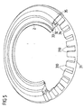
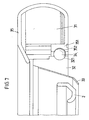
- Show here Fig. 5 to 7 first partial sectional views of the structure of the cutting device 3 with the stator 31, the rotor 32, the blade 33 and the Abstands confronter 2
- Fig. 8 a schematic diagram of the operation of the permanent magnet synchronous motor
- Fig. 9 to 12 Views of individual components of the cutting device 3.
- Fig. 5 to 7 the electric drive to a stator 31 and a rotor 32, which are arranged concentrically to each other, wherein the rotor 32 is rotatably mounted about a rotational axis A on the stator 31 via a ball bearing 34.
- the ball bearing 34 is designed as a ceramic ball bearing, in which ceramic balls are arranged rolling in grooves 321, 352 on the rotor 32 and on the stator 31 and provide a ball bearing between the rotor 32 and the stationary stator 31.
- the stator 32 is enclosed by a housing 35, which comprises the stator 31 and is only spaced over a narrow gap to the rotor 32 (see Figure 7 ).
- the stator 31 enclosing housing 35 is fixedly connected to the stator 31 and has a bearing portion 351, in which the stator-side groove 352 is formed for the ball bearing 34.
- the ball bearing 34 for rotatably supporting the rotor 32 on the stator 31 is a low-friction, almost wear-free arrangement is created, which also requires no additional lubrication. Due to the encapsulation of the stator 31 in the housing 35 and the almost gap-free termination between the housing 35 and the rotor 32, a self-contained arrangement is further created, which has minimal gaps, in which no residues of cut material can settle. In addition, since the encapsulation of the stator 31 and the rotor 32 and in particular the protected arrangement of the ball bearing 34 between the stator 31 and rotor 32 allows easy cleaning of the cutting blade, the hygienic conditions during operation of the cutting blade are significantly improved.
- the blade 33 On the inside of the rotor 32, which rotates about the axis of rotation A in the manner of an internal rotor in the operation of the cutting blade 1, the blade 33 is arranged, which has a lower section (see FIG Fig. 6 and 7 ), protrudes beyond the underside of the rotor 32 and can be brought into contact with the material to be cut for cutting the material to be cut. Radially within the blade 33 is the spacer 2 with its annular portion 22 (see for example Fig. 2 ) and has a distance to the blade 33, which defines a measure of the depth or thickness of the cut material to be cut off.
- Each tooth 310 of the stator 31 carries an armature coil 316a, 316b, 316c with each three armature windings 317, which is fed during operation of the cutting blade 1 with a time-varying sinusoidal current.
- the phase position of the current through the armature coils 316a, 316b, 316c differs here in the manner of a three-phase synchronous motor such that a rotating field is generated, which rotates about the stator 31.
- the rotary field generated in this way cooperates with the permanent magnets 324, 325 arranged on the rotor 32, which poles are reversed relative to one another, so that the north pole N of one permanent magnet 324 and the south pole S of the other permanent magnet 325 point towards the stator 31.
- the excitation field generated by the permanent magnets 324, 325 follows the rotating field generated by the armature coils 316a, 316b, 316c and thus causes a synchronous rotational movement of the rotor 32 about the rotational axis A subsequent to the rotating field of the stator 31.
- the direction of rotation of the rotating field can be selected and thus the direction of rotation of the blade can be specified.
- a direction of rotation of the blade 33 about the axis of rotation A counterclockwise be advantageous so that in operation of the Schneidemessers 1 upon contact of the cut material to be cut with the blade 33 at its front side facing away from the handle 4 (as is usually done) the cutting blade 1 experiences a force away from the user.
- a clockwise direction of rotation may be advantageous. It is also conceivable to design the direction of rotation by variable specification of the phase position switchable, so that during operation of the cutting blade 1, the direction of rotation can be changed.
- the arrangement of the permanent magnets 324, 325 on the rotor 32 and the armature coils 316 316b, 316c repeats periodically in each of the further angular sections, wherein the phase relationship of the currents in the armature coils 316a, 316b, 316c periodically corresponds.
- the number of permanent magnets used 324, 325 and armature coils 316a, 316b, 316c arbitrary, wherein in the illustrated embodiment, three armature coils 316a, 316b, 316c two permanent magnets 324, 325 are assigned.
- the number of armature coils 316a, 316b, 316c and permanent magnets 324, 325 may be selected, for example, depending on the power of the cutting blade 1 to be provided and the torque to be applied.
- FIG. 9 shows first a drawing of the stator 31 on which individual teeth 310 are formed.
- the stator 31 is formed of a plurality of layers of cut iron sheet which are stacked and form a magnetic return for the fields generated in the stator 31 and the rotor 32.
- the multilayer design of the stator 31 reduces the eddy current losses occurring in the stator 31 in a known manner.
- the armature coils 316a, 316b, 316c On the teeth 310 of the stator 31, as in Fig. 8 illustrated, the armature coils 316a, 316b, 316c arranged.
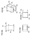
- the armature windings 317 of the armature coils 316a, 316b, 316c are arranged on bobbins 311 which are shown in individual views in FIG Fig. 10a to 10d are shown.
- the bobbins 311 have winding surfaces 314 on which the armature windings 317 are wound and on which the armature windings 317 are held by means of projections 313.
- the bobbin 311 are then inserted with the wound armature windings 317 on each tooth 310 of the stator 31, wherein the tooth 310 engages in a corresponding opening 312 of the bobbin 311 and is held on the stator 31 via a snap closure 315.
- Fig. 11a to 11d the design of the rotor 32 is shown in detail.
- the rotor 32 which is rotatably mounted on the stator 31 via the ball bearing 34, has on its radially outward-facing side a groove 321, in which the balls of the ball bearing 34 engage to support the rotor 32 on the stator 31.
- the rotor 32 is formed substantially annular and has on its inside projections 322, which, as in the enlarged detail views according to FIG Fig. 11c and 11d is shown projecting inwardly from the inside of the rotor 32 and having an inclined edge 322.
- the projections 322 on the rotor 32 are used to attach the blade 33 to the rotor 32.
- the formation of the blade 33 is in detail in Fig. 12a to 12d shown.
- the blade 33 has, for example, out Fig. 12b can be seen, an upper portion 332 of the rotor 32 abuts and a lower portion 333, which is angled relative to the upper portion 332 and sharpened to form a cutting edge.
- the lower section 333 (see FIG Fig. 1 ) from the Cutting device 3 and is brought into contact with the cutting material to be cut for cutting.
- Fig. 12a At the upper edge of the upper portion 332 of the blade 33 are, as in Fig. 12a are recesses 331 arranged, which can be brought to the attachment of the blade 33 on the rotor 32 with the projections 322 on the rotor 32 in engagement. As from the enlarged detail view according to Fig. 12c it can be seen, the recesses 331 also have an oblique edge 334, which in its slope corresponds to the slope of the edge 323 of the projections 322. For attachment of the blade 33 to the rotor 32, the blade 33 from above (see, for example Fig.
- the bevels of the edges 323, 334 on the projections 322 and the recesses 331 are such that they are formed in their slope rising against the direction of rotation of the rotor 32 and the blade 33, the recess 331 at the upper edge of the blade 33 itself So deepened-contrary to the direction of rotation of the blade 33. If the rotary blade 33 is brought into contact with the material to be cut in the feed of the cutting knife 1, the blade 33 experiences a resistance, as a result of which the blade 33 can twist slightly relative to the rotor 32.
- the protrusions 322 assigned to the recesses 331 each travel up the oblique edges 334 of the recesses 331, whereby the blade 33 is pressed into the rotor 32 and thus secured in its connection with the rotor 32.
- the connection between the blade 33 and the rotor 32 thus contracts automatically during operation of the cutting blade 1, so that a release of the connection between the blade 33 and the rotor 32 is counteracted.
- an electrical connection 41 is arranged on the handle 4 of the cutting blade 1 at the end of the handle 4 facing away from the cutting device 3, which serves for the connection of the cutting blade 1 with an external power supply unit.
- an electronic control device 42 is further arranged, which serves to power the electric drive, in particular for supplying the armature coils 316a, 316b, 316c of the stator 31 and at the same time takes over the entire control of the operation of the cutting blade 1.
- switches 51, 52 are arranged on the handle, wherein the switch 51 is arranged on the underside of the handle 4 in the vicinity of the cutting device 3 facing the end and the switch 52 on the rear, the cutting device 3 opposite end of the handle 4.
- the switches 51, 52 cooperate in such a way that for switching on the cutting blade 1, both switches 51, 52 must be actuated simultaneously. This requires that a user with one hand, the switch 51 and the other hand, the switch 52 operated so that it is impossible that a user's hand when putting the cutting blade 1 is in the cutting device 3 and thus the risk of injury a user is considerably reduced during commissioning.
- the switch 51 may be formed as microscoperüngsschalter and capacitive or detect by means of a suitable sensor, whether a user's hand is in the operation of the Schneidemessers 1 in the vicinity of the switch 51.
- the cutting blade 1 may be controlled such that the cutting blade 1 automatically shuts off as soon as the user's hand moves away from the switch 5 1. This prevents that, for example, when the user unintentionally drops the cutting blade 1, the blade 33 continues to rotate.
- the control of the switches 51, 52 can be taken over by the-arranged in the handle 4 control device 42.
- the switch 52 may be formed as a tactile and control switch, via which the speed and performance of the cutting blade 1 can be adjusted.
- the electrical supply of the cutting blade 1 is made via the electrical connection 41 provided on the handle 4. It is conceivable, for example, to connect the cutting blade 1 to an external, permanently installed supply unit, for example a transformer. It is advantageous, however, if external, portable energy storage in the form of capacitive accumulators are used for the electrical supply of the cutting blade 1, which are portable, have stored energy for the operation of the Schneidemessers 1 and after exhausting their energy reserve are rechargeable.
- FIG. 13a . 13b and 14 An embodiment of such accumulators is in Fig. 13a . 13b and 14 shown.
- an accumulator 6 is connected via a connecting line 61 to the electrical connection 41 of the cutting blade 1 and supplies this with electrical energy.
- the accumulator 6 is portable and can be worn by a user B, for example, on the belt.
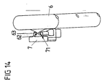
- the accumulator is as in Fig. 14 is suspended via a contact device 7 on the belt of the user B, wherein the accumulator 6 is held via a plug 62 in a receptacle 71 of the contact device 7 and is electrically connected via contacts 63 to the contact device 7.
- the connecting line 61 can be inserted via a plug into the contact device 7 so as to establish the connection of the rechargeable battery 6 to the cutting blade 1.
- the charger is as in Fig. 13a is arranged in the immediate vicinity of the user's workplace B, wherein the accumulator 6 is connected to the charger via a similar contact device 7, as it is also used to connect the accumulator 6 with the Schmeidemesser 1 (see Fig. 13a with the back of the user B on a charger, not shown for charging arranged accumulators 6).
- the --Akkumulatoren 6 are advantageously capacitive and have high performance capacitors with capacities in the order of 350 Farad.
- a schematic schematic diagram of a capacitive accumulator 6 is shown in FIG Fig. 15 shown, in which capacitors C1 to C12, which are in particular designed as double-layer capacitors, are each connected in series with a resistor R1 to R12 connected in parallel and at the terminals +, - provide an output voltage which is the added voltage of the capacitances C1 to C12 corresponds.
- Such capacitive accumulators 6 offer the advantage that they allow a large number of charging cycles, for example of 500,000, require a small charging time of the order of 30 to 60 seconds and also withstand a high current impulse loading load.
- Fig. 16 shows a schematic representation of a charger 8 for charging the capacitive accumulators 6.
- the charger 8 can be designed for a continuous output power of 900W.
- the charger 8 is designed as a switching power supply, which, contrary to a classic linearly regulated power supply with transformer and longitudinally regulated power transistors on the one hand no large and heavy toroidal transformer and on the other hand no active Cooling for the removal of the resulting waste heat to the power transistors requires.
- the charger 8 is designed as a half-bridge push-pull converter with regard to its switched-mode power supply topology and has an active power factor correction (PFC).
- PFC active power factor correction
- a line filter 81 at the AC voltage input prevents high-frequency interference from the switching power supply to the network or vice versa.
- the filtered AC voltage is rectified by a rectifier 82 in the form of a diode bridge and then passes to an input stage with an active power factor correction circuit 83 which primarily provides an up-regulation of the input voltage and at the same time provides a near in-phase current to the input voltage.
- the up-regulated voltage is used to supply a DC intermediate circuit, which in turn provides the input voltage to a half-bridge push-pull converter 84 and to an auxiliary switching power supply 86. Due to the upwards regulation of the mains voltage, it is possible to operate the charger on networks with different voltages.
- the half-bridge push-pull converter 84 breaks down the DC voltage and generates a rectangular, high-frequency AC voltage, which is transmitted via a high-frequency transformer 841 to the output circuit 85 in a fixed ratio.
- the output voltage Ua which is galvanically isolated by the transformer 841, is rectified and smoothed in the output circuit 85 by a two-way rectifier 851 and a filter circuit 852.
- a pulse width modulation control circuit 88, an optocoupler 89 and a control circuit 90 are provided to control the charger 8 circuits 87 to 90 in the form of a PFC control circuit 87.
- a pulse width modulation control circuit 88, an optocoupler 89 and a control circuit 90 are provided to control the charger 8 circuits 87 to 90 in the form of a PFC control circuit 87.
- the auxiliary voltages required for the power supply of the control and monitoring circuits 87 to 90 are generated by an auxiliary switching power supply 86.
- the accumulator 6 is applied to the output terminals of the output circuit 85 and charged via the output voltage Ua.
- the charger 8 is advantageously designed to be mobile, to be carried for use at different locations and to be connected to the existing power grid on site.
- the idea underlying the invention is not limited to the embodiments described above, but can also be used in completely different embodiments.
- the invention is not limited to the use of the described electric drive in the form of a permanent-magnet synchronous motor.
- the use of the presented cutting blade is not limited to the cutting of food. It is also conceivable use of a device with a similar type of drive as a versatile food processor, with which not only food can be cut, but also the züm- stirring or mixing a mass can be used.
- the cutting blade for cutting completely different things, for example, for shearing sheep.
Landscapes
- Life Sciences & Earth Sciences (AREA)
- Forests & Forestry (AREA)
- Engineering & Computer Science (AREA)
- Mechanical Engineering (AREA)
- Food-Manufacturing Devices (AREA)
- Surgical Instruments (AREA)
- Knives (AREA)
- Sawing (AREA)
- Scissors And Nippers (AREA)
Description
- Die Erfindung betrifft ein Schneidemesser insbesondere zum Schneiden von Lebensmitteln nach dem Oberbegriff des Anspruchs 1.
- Ein derartiges Schneidemesser weist eine um eine Rotationsachse drehbar angeordnete Klinge und einen als Elektromotor ausgebildeten elektrischen Antrieb auf, der einen umlaufenen Rotor und einen feststehenden Stator aufweist, die zum Antreiben der Klinge zusammenwirken und die Klinge im Betrieb des Schneidemessers in eine Rotationsbewegung versetzten. Ein derartiges Schneidemesser dient zum Schneiden von Lebensmitteln, insbesondere von Fleisch oder Fisch.
- Ein aus der
EP 0 743 145 B1 bekanntes Schneidemesser ist über eine ein Drehmoment übertragende, flexible Welle mit einem externen elektrischen Antrieb verbunden, wobei die flexible Welle ein mechanisches Getriebe des Schneidemessers antreibt, das über ein Zahnrad in eine umlaufende Verzahnung an einer rotierend an dem Schneidemesser gelagerten Klinge eingreift. Im Betrieb des Schneidemessers versetzt die flexible Antriebswelle das Zahnrad des Getriebes in eine Drehbewegung, die durch ihren Eingriff in die Verzahnung an der rotierend gelagerten Klinge die Klinge in eine Rotationsbewegung versetzt. - Bei einem aus der
EP 0 689 905 B1 bekannten Schneidemesser ist der elektrische Antrieb in den Griff des Schneidemessers verlegt worden und treibt über eine Antriebswelle ein Zahnrad an, das in eine umlaufende Verzahnung an einer rotierend am Schneidemesser gelagerten Klinge eingreift. Der elektrische Antrieb in Form eines Elektromotors im Griff des Schneidemessers wird über eine externe Stromversorgungseinheit in Form eines Transformators mit elektrischer Leistung versorgt, wobei die Stromversorgungseinheit örtlich fest installiert und über ein Kabel begrenzter Länge mit dem Schneidemesser verbunden ist. - Diverse Nachteile ergeben sich bei den aus der
EP 0 689 905 B1 und derEP 0 743 145 B1 bekannten Anordnungen. Das Schneidemesser sowohl derEP 0 689 905 B1 als auch derEP 0 743 145 B1 sind in ihrem Aufbau, insbesondere in der Kopplung des elektrischen Antriebs mit der Klinge, komplex, störanfällig und wartungsintensiv. Insbesondere ist zur Kopplung des elektrischen Antriebs mit der Klinge ein Getriebe erforderlich, das mit einem Zahnrad in eine Verzahnung an der rotierenden Klinge eingreift und diese Verzahnung kämt, um die rotierende Klinge anzutreiben. Dieses bedingt zum einen einen komplizierten Aufbau der verwendeten Klinge, die mit einer Verzahnung versehen werden muss, was die Herstellung der Klinge verkompliziert und verteuert. Zum zweiten erfordert die Lagerung der Klinge und die Kopplung der Klinge mit dem Zahnrad eine ständige Schmierung, die beim Einsatz des Schneidemessers zum Schneiden von Lebensmitteln wie Fleisch oder Fisch herkömmlicherweise mit Pflanzenöl erfolgt, jedoch hygienisch von Nachteil ist. Zum dritten sehen sowohl dieEP 0 689 905 B1 als auch dieEP 0 743 145 B1 eine Kopplung mit einem externen Antrieb oder einer externen Stromversorgungseinheit vor, so dass das Schneidemesser nur in einer begrenzten Reichweite um den externen Antrieb und nicht an beliebigen Orten verwendet werden kann, in seinem Einsatz in der Reichweite begrenzt ist und nicht beliebig mitgeführt werden kann. - Aufgabe der vorliegenden Erfindung ist es, ein Schneidemesser zur Verfügung zu stellen, das hinsichtlich seines Aufbaus derart verbessert ist, dass der Antrieb der Klinge vereinfacht und die Handhabbarkeit des Schneidemessers verbessert ist.
- Diese Aufgabe wird durch einen Gegenstand mit den Merkmalen des Anspruchs 1 gelöst. Erfindungsgemäß ist bei einem Schneidemesser der eingangs genannten Art vorgesehen, dass der Rotor um die Rotationsachse drehbar ist, drehfest mit der Klinge verbunden ist und im Betrieb des Schneidemessers zusammen mit der Klinge um die Rotationsachse umläuft.
- Die Erfindung geht von dem Grundgedanken aus, ein Schneidemesser zur Verfügung zu stellen, das einen Direktantrieb verwendet, das ohne ein zusätzliches Getriebe zur Kopplung des elektrischen Antriebs mit der Klinge auskommt. Vorgesehen ist hierbei, dass der Rotor des aus dem Rotor und dem Stator gebildeten Antriebs drehbar gelagert ist und um die Rotationsachse umläuft, wobei die Klinge mit dem Rotor gekoppelt ist und zusammen mit dem Rotor in eine Drehbewegung versetzt wird. Rotor und Stator wirken hierbei elektromotorisch zusammen, wobei der Rotor im Betrieb relativ zum Stator rotiert und dadurch die drehfest mit dem Rotor verbundene Klinge antreibt.
- Ein wesentlicher Vorteil der erfindungsgemäßen Anordnung ist, dass kein zusätzliches Getriebe zur Kopplung des Antriebs mit der Klinge vorgesehen sein muss. Insbesondere entfällt die Notwendigkeit für zusätzliche Zahnräder, die in eine Verzahnung an der Klinge eingreifen, so dass sich zum einen der Aufbau des Antriebs und zum anderen die Geometrie der Klinge wesentlich vereinfacht werden kann. Dadurch, dass auf ein Getriebe verzichtet werden kann, reduziert sich die Anzahl der erforderlichen Verschleißteile des Schneidemessers erheblich, so dass sich ein effizientes und reibungs-, wartungs- und verschleißarmes Schneidemesser ergibt. Dadurch, dass zudem an der Klinge keine Verzahnung mehr vorgesehen sein muss, kann die Klinge erheblich kostengünstiger und einfacher hergestellt werden, wodurch sich insbesondere die Kosten für den Betrieb des Schneidemessers bei Austausch abgenutzter oder fehlerhafter Klingen erheblich reduzieren.
- Zudem ist die Klinge drehfest am Rotor angeordnet, muss somit nicht mehr gesondert an dem Schneidemesser gelagert werden, sondern rotiert im Betrieb vielmehr zusammen mit dem Rotor um den Stator. Dadurch ist eine Schmierung der Klinge nicht mehr erforderlich, so dass auch ausgeschlossen werden kann, dass Schmiermittel im Betrieb des Schneidemessers in Kontakt mit der Klinge kommt, so dass die hygienischen Bedingen insbesondere beim Schneiden von Lebnesmitteln erheblich verbessert sind.
- Bevorzugt sind der Stator, der Rotor und die Klinge im Wesentlichen ringförmig ausgebildet und konzentrisch zueinander angeordnet. Der Rotor kann hierbei über ein Kugellager, insbesondere ein Keramikkugellager drehbar am Stator gelagert sein. Durch Verwendung eines solchen kugellagers kann vollständig auf eine Schmierung des am Stator gelagerten Rotors verzichtet werden, so dass eine Schmierung einzelner Teile des Schneidemessers insgesamt nicht mehr erforderlich ist. Durch Verwendung eines offenen Kugellagers, insbesondere eines Keramikkugellagers oder auch eines Stahlkugellagers, wird zudem gewährleistet, dass die Lagerung des Rotors am Stator ohne Zusatzschmierung eine geringe Reibung aufweist und auch lange Lagerstandzeiten ermöglicht, ohne die Betriebsbereitschaft des Schneidemessers zu beeinflussen.
- Vorteilhafterweise ist der Rotor nach Art eines Innenläufers radial innerhalb des Stators und die Klinge radial innerhalb des Rotors an der Innenseite des Rotors angeordnet. Der Stator bildet somit einen äußeren Ring, an dem der Rotor innenliegend drehbar gelagert ist und an seiner Innenseite die Klinge hält. Die Kopplung der Klinge mit dem Rotor erfolgt hierbei drehfest, so dass die Klinge im Betrieb des Schneidemessers zusammen mit dem Rotor im Stator umläuft.
- Die Klinge kann zur Befestigung form- oder kraftschlüssig an dem Rotor gehalten werden, wobei die Verbindung zwischen dem Rotor und der Klinge vorteilhafterweise lösbar ausgebildet ist. Zur Befestigung der Klinge an dem Rotor wird die Klinge dann beispielsweise von oben in den Rotor eingesteckt und gerät beispielsweise über einen Schnappverschluss mit dem Rotor in Eingriff, der die Klinge drehfest hält. Der Schnappverschluss kann beispielsweise über am Rotor ausgebildete Vorsprünge ausgebildet sein, die in Aussparungen an der Klinge eingreifen.
- In einer vorteilhaften Ausgestaltung ist die Verbindung zwischen dem Rotor und der Klinge derart beschaffen, dass sie sich im Betrieb des Schneidemessers selbsttätig festzieht. Dieses kann beispielsweise dadurch erreicht werden, dass die Aussparungen an der Klinge, in die Vorsprünge des Rotors zur Befestigung eingreifen, mit einer Schräge versehen werden, die-entgegen der Drehrichtung des Rotors gerichtete ist, so dass die Vorsprünge bei einer Drehbewegung des Rotors zusammen mit der Klinge auf die Schräge auflaufen und auf diese Weise die Befestigung der Klinge am Rotor festigen.
- Erfindungsgemäß ist ein elektrischer Antrieb nach Art eines Direktantriebs vorgesehen, dessen Rotor unmittelbar mit der Klinge gekoppelt ist und somit kein Getriebe zum Antreiben der Klinge erfordert. Unterschiedliche Ausgestaltungen von Elektromotoren mit einem Stator und einem Rotor sind prinzipiell bekannt und können eingesetzt werden. In einer konkreten Ausgestaltung, auf die die Erfindung jedoch nicht beschränkt ist, kann der Antrieb beispielsweise nach Art eines permanenterregten Dreiphasen-Synchronmotors ausgebildet sein, bei dem am Rotor zur Permanenterregung Permanentmagneten am Stator Ankerwicklungen aufweisende Ankerspulen angeordnet sind, die derart zusammenwirken, dass ein Stromfluss durch die Ankerspulen eine Rotationsbewegung des Rotors verursacht. Beispielsweise- können -hierbei in einen Winkelabschnitt des Stators drei Ankerspulen angeordnet sein, die zwei Permanentmagneten des Rotors zugeordnet sind. Die Ankerspulen werden dann im Betrieb des Schneidemessers jeweils von einem zeitlich veränderlichen sinusförmigen Strom durchflossen, wobei sich die Phasen des Stroms in den Ankerspulen des Winkelabschnitts derart unterscheiden, dass sich ein umlaufendes Drehfeld ergibt. Die Polung der Permanentmagneten in dem Winkelabschnitt ist so gewählt, dass jeweils abwechselnd der Nordpol des einen Permanentmagneten und der Südpol des benachbarten anderen Permanentmagneten vom Rotor zum Stator hin weist, so dass die Permanentmagneten ein Erregerfeld erzeugen, dass mit dem umlaufenden Drehfeld der Ankerspulen derart zusammenwirkt, dass der Rotor im Betrieb des Schneidemessers dem Drehfeld der Ankerspulen nachfolgt.
- Nach dem Prinzip eines Synchronmotors wird im Stator wird somit durch Speisung der Ankerspulen ein umlaufendes Drehfeld erzeugt, dass mit dem Feld der Permanentmagneten des Rotors zum Antreiben des Rotors zusammenwirkt, wobei der Rotor synchron mit dem Drehfeld des Stators umläuft. Der Stator ist hierbei als magnetischer Rückschluss ausgebildet und weist Zähne auf, die jeweils eine Ankerspule zur Erzeugung des Drehfelds des Stators tragen.
- Im Betrieb des Schneidemessers werden die Ankerspulen des Stators mit einem mit einer Phase behafteten sinusförmigen Strom gespeist, so dass sich ein umlaufendes Drehfeld am Stator ergibt. Vorteilhafterweise erfolgt die Speisung der Ankerspulen hierbei über eine im Griff des Schneidemessers angeordnete elektronische Steuervorrichtung, die zum einen die Speisung--und Steuerung des Elektromotors, -zum anderen aber auch die gesamte Betriebsteuerung des Schneidemessers übernimmt. Dadurch, dass die elektronische Steuervorrichtung im Griff des Schneidemessers angeordnet ist, kann zum einen eine platzsparende Anordnung für die elektronische Steuervorrichtung bereitgestellt und zum anderen eine vollständige Kapselung der elektronischen Steuervorrichtung zur Verfügung gestellt werden, indem die elektronische Steuervorrichtung vom Griff eingeschlossen und abgedeckt ist. Eine derartige Kapselung der elektronischen Steuervorrichtung ist insbesondere vorteilhaft, um den Eintritt von Feuchtigkeit und Verunreinigungen in die elektronische Steuervorrichtung im Betrieb des Schneidemessers zu vermeiden.
- Vorteilhaft ist weiterhin, den aus dem Rotor und dem Stator gebildeten Antrieb in ein Gehäuse zum Schutz gegen Verunreinigungen einzufassen. Das Gehäuse kann hierbei derart beschaffen sein, dass es den Stator nach außen hin einkapselt und derart im Wesentlichen spaltfrei zum Rotor abschließt, dass lediglich die Verbindung der Klinge mit dem Rotor ermöglicht wird, der Bereich zwischen Rotor und Stator, insbesondere die Lagerung des Rotors am Stator jedoch geschützt ist. Auf diese Weise kann verhindert werden, dass Verunreinigungen beispielsweise in Form von Resten des Schneidguts in den Bereich des Rotors und Stators eindringen können. Gleichermaßen ermöglicht die Kapselung des Rotors und des Stators durch das Gehäuse eine einfache Reinigung des Schneidemessers, ohne dass Rotor und Stator auseinander genommen werden müssen.
- In einer Weiterbildung des Schneidemessers können zwei Schalter zum Einschalten des Schneidemessers am Griff angeordnet sein, wobei sich der eine Schalter an einem hinteren Ende des Griffs und der andere Schalter in einem Bereich des Griffs, an dem ein Benutzer im Betrieb anfasst, beispielsweise an einer Unterseite in einem vorderen des Griffs, befindet und das Schneidemesser nur durch ein gleichzeitiges Betätigen beider Schalter einschaltbar ist. Eine derartige Anordnung ist insbesondere vorteilhaft, um eine sichere Inbetriebnahme des Schneidemessers zu gewährleisten, ohne dass eine Verletzungsgefahr durch die rotierende Klinge für einen Benutzer besteht. Dieses wird erreicht, indem das Schneidemesser nur durch ein gleichzeitiges Betätigen beider Schalter einschaltbar ist, wobei sich die eine Hand des Benutzers am ersten Schalter und die zweite Hand des Benutzers am zweiten Schalter befinden muss. Dadurch, dass die Schalter an unterschiedlichen Orten des Griffes angeordnet werden, ist ein gleichzeitiges Betätigen beider Schalter durch nur eine Hand ausgeschlossen und somit gewährleistet, dass bei Inbetriebnahme des Schneidemessers in der Tat beide Hände des Benutzers im Bereich der Schalter und außerhalb des Bereichs der Klinge des Schneidemessers angeordnet sind. Selbstverständlich ist grundlegend auch das Vorsehen nur eines Schalters möglich, mit dem das Schneidemesser eingeschaltet und geregelt werden kann.
- In einer vorteilhaften Ausgestaltung ist einer der Schalter als Näherungsschalter ausgebildet, wobei das Schneidemesser nur betätigbar ist, wenn sich eine Hand des Benutzers in der Nähe dieses Näherungsschalters befindet. Diese Ausgestaltung ist vorteilhaft, um zu verhindern, dass der Benutzer im Betrieb seine Hand vom Griff des Schneidemessers entfernt und in den Bereich der Klinge des Schneidemessers bringt oder das Schneidemesser beispielsweise beim Fallenlassen Verletzung verursacht. Durch die Ausbildung des Schalters als Näherungsschalters, beispielsweise als kapazitiver oder als einen Sensor aufweisender Näherangsschatter, wird eine Steüerung des Schneidemessers ermöglicht, bei der sich das Schneidemesser automatisch abschaltet, sobald sich die Hand des Benutzer von dem Näherungsschalter entfernt. Dieses bietet eine größtmögliche Sicherheit für den Benutzer sowohl beim Einschaltvorgang als auch im Betrieb des Schneidemessers.
- In einer bevorzugten Ausgestaltung weist das Schneidemesser zudem einen Abstandshalter auf, der über eine Verstellvorrichtung mit einem feststehenden Abschnitt, beispielsweise dem Griff des Schneidemessers verbunden ist, wobei der Abstandshalter mittels der Verstellvorrichtung in Richtung der Rotationsachse relativ zur Klinge verstellbar ist und über die Verstellvorrichtung an dem feststehenden Abschnitt des Schneidemessers gehalten wird. Dieser Abstandshalter ist mit Abstand zur Klinge an dem feststehenden Abschnitt des Schneidemessers angeordnet und gibt ein Maß für die Tiefe des abzuschneidenden Schneidgutes vor. Das Schneidgut wird durch die Klinge abgeschnitten und zwischen der Klinge und dem Abstandshalter hindurchgeführt, wobei der Abstand zwischen dem Abstandshalter und der Klinge die Tiefe bzw. Dicke des abgeschnittenen Schneidgutes bestimmt. Dadurch, dass dieser Abstandshalter über eine Verstellvorrichtung mit dem feststehenden Abschnitt des Schneidmessers verbunden wird, wird eine vorteilhafte Verbindung des Abstandshalters mit dem feststehenden Abschnitts des Schneidemessers geschaffen, in dem die Verstellvorrichtung eine Doppelfunktion erfüllt und einerseits die Verstellbarkeit des Abstandhalters relativ zum Schneidemesser gewährleistet und andererseits die Anbindung des Abstandshalters an das Schneidemesser herstellt. Mittels einer derartigen Anordnung kann auf die Verwendung zusätzlicher Feststellschrauben zur Verbindung des Abstandshalters mit dem feststehenden Abschnitts des Schneidemessers verzichtet und die Anbindung allein über die Verstellvorrichtung hergestellt werden.
- Bevorzugt ist der feststehende Abschnitt des Schneidemessers durch den Griff des Schneidemessers ausgebildet, an dem der Abstandshalter angeordnet ist und an dem ein Benutzer das Schneidemesser greifen und führen-kann.
- Bei dem Schneidemesser ist der Abstandshalter mit Abstand zur drehbar über dem Rotor an dem Stator gelagerten Klinge angeordnet. Im Betrieb des Schneidemessers rotiert die Klinge relativ zu dem feststehenden Abstandshalter, wobei der Abstand zwischen dem Abstandshalter und der Klinge die Tiefe des abzuschneidenden Schneidgutes definiert. Bevorzugt weist der Abstandshalter einen ringförmigen Abschnitt auf, der im Wesentlichen konzentrisch zu der drehbar gelagerten Klinge angeordnet ist, wobei im Betrieb das abzuschneidende bzw. abgeschnittene Schneidgut zwischen dem ringförmigen Abschnitt und der Klinge hindurchgeführt wird und somit der Abstand zwischen dem ringförmigen Abschnitt des Abstandshalters und der drehbar gelagerten Klinge das Maß für die Tiefe des abgeschnittenen Schneidgutes vorgibt.
- Der konzentrisch zu der drehbar gelagerten Klinge angeordnete, ringförmige Abschnitt des Abstandhalters kann über einen Bügel mit der Verstellvorrichtung und über die Verstellvorrichtung mit dem feststehenden, beispielsweise durch den Griff des Schneidemessers ausgebildeten Abschnitt des Schneidemessers verbunden sein. Der Abstandshalter erstreckt sich somit über den Bügel vom Griff in den Bereich der drehbar gelagerten Klinge, so dass der ringförmige Abschnitt des Abstandshalters in gewünschter Weise zur Klinge positioniert ist.
- Bei dem erfindungsgemäßen Schneidemesser ist der durch den Rotor und Stator gebildete elektrische Antrieb als Direktantrieb unmittelbar am Schneidemesser angeordnet. Um diesen elektrischen Antrieb mit elektrischer Leistung zu versorgen, ist das Schneidemesser vorteilhafterweise mit einem externen Energiespeicher, der beispielsweise als kapazitiver Akkumulator mit mindestens einem Kondensator zur kapazitiven Speicherung elektrischer Energie ausgebildet ist, verbindbar. Dieser externe Energiespeicher in Form des Akkumulators kann hierbei tragbar ausgebildet sein, so dass der Akkumulator im Betrieb durch einen Benutzer auf einfache und leicht handhabbare Weise mitgeführt werden kann. Zum Betrieb des Schneidemessers wird der externe Energiespeicher hierbei mit dem Schneidemesser verbunden und versorgt das Schneidemesser mit Energie. Nachdem sich die Energiereserve des als Akkumulator ausgebildeten Energiespeichers erschöpft hat, kann der Energiespeicher von dem Schneidemesser gelöst werden und über eine externe Ladestation aufgeladen werden. Nach dem Aufladen des Akkumulators kann der Akkumulator dann wiederum zur Versorgung des Schneidemessers eingesetzt werden, wobei der Betrieb des Schneidemessers auch in der Aufladezeit durch einen Austauschakkumulator fortgeführt werden kann. Für einen derartigen kapazitiven Akkumulator könne beispielsweise Hochleistungskondensatoren eingesetzt werden, die eine große Anzahl von Ladezyklen ohne Beeinflussung ihrer Betriebsleistung aushalten, eine extrem kurze Ladezeit erfordern und einer Impulsbelastung mit großen Strömen standhalten. Derartige kapazitive Akkumulatoren bieten insbesondere in der möglichen Anzahl der Ladezyklen und der Ladezeit Vorteile gegenüber herkömmlichen elektrochemischen Akkumutatoren.
- Der der Erfindung zugrunde liegende Gedanke soll nachfolgend anhand der in den Figuren dargestellten Ausführungsbeispiele näher erläutert werden. Es zeigen:
- fig. 1
- eine perspektivische Ansicht eines Schneidemessers von der Seite;
- Fig. 2
- eine perspektivische Ansicht des Schneidemessers gemäß
Fig. 1 von oben; - Fig. 3
- eine perspektivische Ansicht des Schneidemessers gemäß
Fig. 1 und2 schräg von oben; - Fig. 4
- eine perspektivische Ansicht des Schneidemessers gemäß
Fig. 1 bis 3 schräg von unten; - Fig. 5
- eine teilweise freigeschnittene, perspektivische Ansicht des elektrischen Antriebs des Schneidemessers mit einem Stator, einem Rotor und einer Klinge;
- Fig. 6
- eine perspektivische Teilschnittansicht durch den Stator, den Rotor und die Klinge;
- Fig. 7
- eine weitere Teilschnittansicht des Stators, des Rotors und der Klinge;
- Fig. 8
- eine schematische Darstellung der Anordnung der Permanentmagneten
- -
- am Rotor und der Arikerspulen am Stator;
- Fig. 9
- eine schematische Querschnittsansicht eines Winkelausschnitts des Stators;
- Fig. 10a bis 10d
- gesonderte Ansichten des Spulenkörpers zur Anordnung der Ankerspulen auf dem Stator;
- Fig. 11 a
- perspektivische Ansicht des Rotors;
- Fig. 11 b
- seitliche Teilschnittansicht des Rotors;
- Fig. 11c
- Ansicht des Rotors in Ausschnitt IV gemäß
Fig. 11b ; - Fig. 11 d
- Ansicht des Rotors in Ausschnitt III gemäß
Fig. 11 b;fig. 12a perspektivische Ansicht der Klinge; - Fig. 12b
- seitliche Teilschnittansicht der Klinge;
- Fig. 12c
- Ansicht der Klinge in Ausschnitt VI gemäß
Fig. 12b ; - Fig. 12d
- Ansicht der Klinge in Ausschnitt V gemäß
Fig. 12b ; - Fig. 13a
- eine schematische Darstellung des Betriebs des Schneidemessers durch einen Benutzer;
- Fig. 13b
- eine vergrößerte Darstellung des durch einen Benutzer betriebenen Schneidemessers;
- Fig. 14
- eine perspektivische Ansicht eines Akkumulators in einer Kontaktvorrichtung;
- Fig. 15
- eine schematische Schaltskizze des Aufbaus des Akkumulators und
- Fig. 16
- eine schematische Schaltskizze des Aufbaus des Ladegeräts.
-
Fig. 1 bis 4 zeigen eine Ausführungsform eines Schneidemessers 1 mit einer rotierend an dem Schneidemesser 1 angeordneten, drehbaren Klinge 33, die sich im Betrieb des Schneidemessers 1 um eine Rotationsachse A dreht und von einem Benutzer entlang einer zu schneidenden Ware geführt wird. Das Schneidemesser 1 weist einen Griff 4 auf, an dem der Benutzer das Schneidemesser 1 greifen und führen kann. Das Schneidemesser 1 dient zum Schneiden insbesondere von Lebensmitteln wie Fleisch oder Fisch, ist portabel ausgeführt und ist von-einem- Benutzer mit einer Hand handhabbar. Der Benutzer greift hierbei das Schneidemesser 1 am Griff 4 und führt das Schneidemesser 1 mit der nach unten vorstehenden Klinge 33 (sieheFig. 1 ) entlang des zu schneidenden Schneidgutes. - Im Betrieb des Schneidemessers 1 wird die Klinge 33 durch einen elektrischen Antrieb in eine Rotationsbewegung um die Rotationsachse A versetzt. Bei dem in
Fig. 1 bis 4 dargestellten Schneidemesser 1 ist dieser elektrische Antrieb hierbei in Form eines Direktantriebs ausgebildet, der direkt mit der Klinge 33 gekoppelt ist und an das vordere Ende des Griffs 4 anschließt. Der elektrische Antrieb weist, wie beispielsweise ausFig. 2 ersichtlich ist, einen äußeren Stator 31, einen drehbar zum Stator 31 gelagerten Rotor 32 -und eine Klinge 33 auf, die drehfest mit dem Rotor 32 verbunden ist. Der Stator 31, der Rotor 32 und die Klinge 33 bilden zusammen eine Schneidevorrichtung 3 aus, deren rotierende Klinge 33 im Betrieb des Schneidemessers 1 entlang des zu schneidenden Schneidgutes geführt wird und mit der das zu bearbeitende Schneidgutes in Scheiben geschnitten wird. - Am Griff 4 des Schneidemessers 1 ist ein Abstandshalter 2 angeordnet, der über eine Verstellvorrichtung 24 nach Art einer Verstellschraube mit dem Griff 4 gekoppelt ist und einen ringförmigen Abschnitt 22 aufweist, der über einen Bügel 21 mit der Verstellvorrichtung 24 verbunden und konzentrisch zur Klinge 33 angeordnet ist. Der ringförmige Abschnitt 22 des Abstandshalters 2 ist mit Abstand zur Klinge 33 angeordnet, wobei der Abstand zwischen dem ringförmigen Abschnitt 22 und der Klinge 33 die Tiefe bzw. Dicke des abzuschneidenden Schneidgutes bestimmt.
- Über die Verstellvorrichtung 24 ist der Abstandshalter 2 zum Einen mit dem Griff 4 verbunden und an dem Griff 4 gehalten und zum Anderen in Richtung der Rotationsachse A relativ zur Klinge 33 verstellbar, so dass der Anstand zwischen dem ringförmigen Abschnitt 22 des Abstandshalters 2 und der Klinge 33 zum Schneiden von Schneidgut unterschiedlicher Dicke verändert werden kann. Mittels der Verstellvorrichtung 24 ist der Abstandshalter 2 am Griff 4 festgelegt und ausschließlich in Richtung der Rotationsachse A einstellbar. Ein Verschieben oder eine Verstellung des Abstandshalters 2 in der Ebene senkrecht zur Rotationsachse A ist ausgeschlossen.
- Das Schneidemesser 1 weist einen Griff 4 auf, an dem ein Benutzer das Schneidemesser 1 anfassen und führen kann. Denkbar ist in diesem Zusammenhang, den Griff 4 mit Griffschalen zu versehen, die ausgetauscht werden können. Abhängig von der Handgröße eines Benutzers können dann unterschiedliche Griffschalen mit unterschiedlichen Durchmessern verwendet werden, mittels derer der Griff 4 in seinem Durchmesser dem Benutzer angepasst werden kann. Ein Benutzer mit einer kleinen Hand kann dann beispielsweise eine Griffschale mit einem kleinen Durchmesser verwenden, während ein Benutzer mit einer größeren Hand eine Griffschale mit einem entsprechend größeren Durchmesser benutzt. Durch Verwendung dieser unterschiedlichen Griffschalen kann der Bedienungskomfort und die Greifbarkeit des Schneidemessers 1 für einen Benutzer verbessert werden.
- Wie vorangehend bereits erwähnt, ist der elektrische Antrieb des Schneidemessers 1 nach Art eines Direktantriebs mit einem Stator 31 und einem Rotor 32 ausgebildet und mit einer drehfest mit dem Rotor 32 verbundenen Klinge 33 ausgestattet, die im Betrieb des Schneidemessers 1 entlang des zu bearbeitenden Schneidgutes geführt wird und das Schneidgut in gewünschter Weise schneidet. Der Stator 31, der Rotor 32 und die Klinge 33 sind im Wesentlichen ringförmig ausgebildet und konzentrisch zur Rotationsachse A, um die der Rotor 32 und die mit dem Rotor 32 gekoppelte Klinge 33 drehbar sind, angeordnet.
- Der elektrische Antrieb, bestehend aus dem Stator 31 und dem Rotor 32, ist bei dem Ausführungsbeispiel gemäß
Fig. 1 bis 4 nach Art eines permanenterregten Synchronmotors ausgebildet und soll nachfolgend im Detail beschrieben werden. Es wird jedoch angemerkt, dass selbstverständlich anstelle der hier konkret beschriebenen Ausführungsform des elektrischen Antriebs 31, 32 auch andere Bauformen von Elektromotoren, beispielsweise bürstenkommutierte Gleichstrommotoren oder dergleichen, denkbar und einsetzbar sind. Wesentlich bei der vorgestellten Erfindung ist, dass der elektrische Antrieb als Direktantrieb ausgebildet ist, bei dem der Rotor 32 um die Rotationsachse A drehbar gelagert ist, drehfest mit der Klinge 33 verbunden ist und im Betrieb des Schneidemessers 1 zusammen mit der Klinge 33 um die Rotationsachse A umläuft. - Bei dem in
Fig. 1 bis 4 dargestellten Ausführungsbeispiel wird als elektrischer Antrieb ein Elektromotor nach Art eines permanenterregten Synchronmotors verwendet, der nachfolgend anhand vonFig. 5 bis 12 erläutert werden soll. Hierbei zeigenFig. 5 bis 7 zunächst Teilschnittansichten des Aufbaus der Schneidvorrichtung 3 mit dem Stator 31, dem Rotor 32, der Klinge 33 und dem Abstandshälter 2,Fig. 8 eine Prinzipskizze der Funktionsweise des permanenterregten Synchronmotors undFig. 9 bis 12 Ansichten einzelner Komponenten der Schneidvorrichtung 3. - Wie zunächst aus
Fig. 5 bis 7 ersichtlich ist, weist der elektrische Antrieb einen Stator 31 und einen Rotor 32 auf, die konzentrisch zueinander angeordnet sind, wobei der Rotor 32 über ein Kugellager- 34 drehbar um die- Rotationsachse A an dem Stator 31 gelagert ist. Das Kugellager 34 ist als Keramikkugellager ausgebildet, bei dem keramische Kugeln in Nuten 321, 352 am Rotor 32 bzw. am Stator 31 rollend angeordnet sind und ein Kugellager zwischen dem Rotor 32 und dem feststehenden Stator 31 zur Verfügung stellen. Der Stator 32 ist durch ein Gehäuse 35 eingefasst, das den Stator 31 umfasst und lediglich über einen schmalen Spalt zum Rotor 32 beabstandet ist (sieheFig.7 ). Das den Stator 31 einfassende Gehäuse 35 ist fest mit dem Stator 31 verbunden und weist einen Lagerabschnitt 351 auf, in den die statorseitige Nut 352 für das Kugellager 34 eingeformt ist. - Durch das Kugellager 34 zur drehbaren Lagerung des Rotors 32 am Stator 31 wird eine reibungsarme, nahezu verschleißfreie Anordnung geschaffen, die zudem kein zusätzliches Schmierungsmittel benötigt. Durch die Kapselung des Stators 31 im Gehäuse 35 und den nahezu spaltfreien Abschluss zwischen dem Gehäuse 35 und dem Rotor 32 wird weiterhin eine in sich geschlossene Anordnung geschaffen, die minimale Spalten aufweist, in denen sich keine Reste von Schneidgut absetzen können. Da zudem die Kapselung des Stators 31 und des Rotors 32 und insbesondere die geschützte Anordnung des Kugellagers 34 zwischen Stator 31 und Rotor 32 eine leichte Reinigung des Schneidemessers ermöglicht, sind die hygienischen Bedingungen beim Betrieb des Schneidemessers erheblich verbessert.
- An der Innenseite des im Betrieb des Schneidemessers 1 nach Art eines Innenläufers im Stator 31 um die Rotationsachse A umlaufenden Rotors 32 ist die Klinge 33 angeordnet, die mit einem unteren Abschnitt (siehe
Fig. 6 und7 ), über die Unterseite des Rotors 32 hinausragt und zum Schneiden des Schneidgutes mit dem Schneidgut in Kontakt gebracht werden kann. Radial innerhalb der Klinge 33 ist der Abstandshalter 2 mit seinem ringförmigen Abschnitt 22 (siehe beispielsweiseFig. 2 ) angeordnet und weist einen Abstand zur Klinge 33 auf, der ein Maß für die Tiefe bzw. Dicke des abzuschneidenden Schneidgutes definiert. - Bei dem aus dem Stator 31 und dem Rotor 32 gebildete, nach Art eines permanenterregten Synchronmotors aufgebaute elektrische Antrieb sind auf Zähnen 310 des Stators 31 Ankerspulen zur Erzeugung eines umlaufenden Drehfeldes und auf dem Rotor 32 zur Erzeugung eines Erregerfeldes Permanentmagneten angeordnet. Eine Prinzipskizze der Anordnung dieser Ankerspulen 316a, 316b, 316c auf dem Stator 31 und der Permanentmagneten 324, 325 auf dem Rotor 32 ist in
Fig. 8 dargestellt, die die Anordnung in einem Winkelabschnitt α des elektrischen Antriebs zeigt. Jeder Zahn 310 des Stators 31 trägt eine Ankerspule 316a, 316b, 316c mit Jeweils drei Ankerwicklungen 317, die im Betrieb des Schneidemessers 1 mit einem zeitlich veränderlichen, sinusförmigen Strom gespeist wird. Die Phasenlage des Stroms durch die Ankerspulen 316a, 316b, 316c unterscheidet sich hierbei nach Art eines Dreiphasen-Synchronmotors derart, dass ein Drehfeld erzeugt wird, das um den Stator 31 umläuft. Das so erzeugte Drehfeld wirkt mit den auf dem Rotor 32 angeordneten Permanentmagneten 324, 325 zusammen, die umgekehrt zueinander gepolt sind, so dass der Nordpol N des einen Permanentmagneten 324 und der Südpol S des anderen Permanentmagneten 325 zum Stator 31 hin weisen. Im Betrieb folgt das durch die Permanentmagneten 324, 325 erzeugte Erregerfeld dem durch die Ankerspulen 316a, 316b, 316c erzeugten Drehfeld nach und verursacht somit eine dem Drehfeld des Stators 31 nachfolgende synchrone Drehbewegung des Rotors 32 um die Rotationsachse A. - Abhängig von der Phasenlage der Strömen in den einzelnen Ankerspulen 316a, 316b, 316c kann die Umlaufrichtung des Drehfeldes gewählt werden und somit die Drehrichtung des Messers vorgegeben werden. Bei Benutzung des Schneidemessers 1 durch einen Rechtshänder kann hierbei eine Drehrichtung der Klinge 33 um die Rotationsachse A entgegen dem Uhrzeigersinn vorteilhaft sein, damit im Betrieb des Schneidemessers 1 bei Kontakt des zu schneidenden Schneidgutes mit der Klinge 33 an ihrem vom Griff 4 abgewandten, vorderen Abschnitt (wie dies üblicherweise erfolgt) das Schneidemesser 1 eine Kraft vom Benutzer weg erfährt. Umgekehrt kann bei einem Linkshänder eine Drehrichtung im Uhrzeigersinn vorteilhaft sein. Denkbar ist auch, die Drehrichtung durch variable Vorgabe der Phasenlage umschaltbar auszulegen, so dass im Betrieb des Schneidemessers 1 die Drehrichtung geändert werden kann.
- Die Anordnung der Permanentmagneten 324, 325 auf dem Rotor 32 und der Ankerspulen 316 316b, 316c wiederholt sich jeweils periodisch in den weiteren Winkelabschnitten, wobei sich die Phasenlage der Ströme in den Ankerspulen 316a, 316b, 316c periodisch entspricht. Grundsätzlich ist die Anzahl der verwendeten Permanentmagneten 324, 325 und Ankerspulen 316a, 316b, 316c beliebig, wobei bei der dargestellten Ausführungsform jeweils drei Ankerspulen 316a, 316b, 316c zwei Permanentmagneten 324, 325 zuzuordnen sind.
- Die Anzahl der Ankerspulen 316a, 316b, 316c und Permanentmagneten 324, 325 kann beispielsweise abhängig von der zur Verfügung zu stellenden Leistung des Schneidmessers 1 und dem aufzubringenden Drehmoment gewählt werden.
- In
Fig. 9 bis Fig. 12 sind die für den elektrischen Antrieb verwendeten Bauteile im Einzelnen dargestellt.Fig. 9 zeigt zunächst eine Zeichnung des Stators 31, an dem einzelne Zähne 310 ausgebildet sind. Der Stator 31 ist aus mehreren Lagen von geschnittenem Eisenblech ausgebindet, die-übereinander angeordnet sind und einen magnetischen Rückschluss für die in Stator 31 und Rotor 32 erzeugten Felder ausbilden. Die mehrlagige Ausbildung des Stators 31 verringert in bekannter Weise die im Stator 31 auftretenden Wirbelstromverluste. - Auf den Zähnen 310 des Stators 31 werden, wie in
Fig. 8 veranschaulicht ist, die Ankerspulen 316a, 316b, 316c angeordnet. Um zu verhindern, dass die Kanten an den den Stator 31 ausbildenden Blechen die Ankerwicklungen 317 und deren isolierende Beschichtung beschädigen, sind die Ankerwicklungen 317 der Ankerspulen 316a, 316b, 316c auf Spulenkörpern 311 angeordnet, die in einzelnen Ansichten inFig. 10a bis 10d dargestellt sind. Die Spulenkörper 311 weisen Wickelflächen 314 auf, auf die die Ankerwicklungen 317 aufgewickelt werden und an denen die Ankerwicklungen 317 mittels Überständen 313 gehalten werden. Die Spulenkörper 311 werden dann mit dem aufgewickelten Ankerwicklungen 317 auf jeweils einen Zahn 310 des Stators 31 gesteckt, wobei der Zahn 310 in eine entsprechende Öffnung 312 des Spulenkörpers 311 eingreift und über einen Schnappverschluss 315 am Stator 31 gehalten wird. - In
Fig. 11a bis 11d ist die Bauform des Rotors 32 im Einzelnen dargestellt. Der Rotor 32, der über das Kugellager 34 drehbar am Stator 31 gelagert ist, weist an seiner radial nach außen weisenden Seite eine Nut 321 auf, in die die Kugeln des Kugellagers 34 eingreifen, um den Rotor 32 am Stator 31 zu lagern. Der Rotor 32 ist im Wesentlichen ringförmig ausgebildet und weist an seiner Innenseite Vorsprünge 322 auf, die, wie in den vergrößerten Detailansichten gemäßFig. 11c und 11d dargestellt ist, nach innen von der Innenseite des Rotors 32 abstehen und eine schräge Kante 322 aufweisen. - Die Vorsprünge 322 am Rotor 32 dienen zur Befestigung der Klinge 33 am Rotor 32. Die Ausbildung der Klinge 33 ist im Einzelnen in
Fig. 12a bis 12d gezeigt. Die Klinge 33 weist, wie beispielsweise ausFig. 12b ersichtlich ist, einen oberen Abschnitt 332 der am Rotor 32 anliegt und einen unteren Abschnitt 333 auf, der gegenüber dem oberem Abschnitt 332 abgewinkelt ist und zur Ausbildung einer Schneide geschärft ist. Im Betrieb des Schneidemessers 1 steht der untere Abschnitt 333 (sieheFig. 1 ) aus der Schneidevorrichtung 3 hervor und wird mit dem zu schneidenden Schneidgut zum Schneiden in Kontakt gebracht. - An der oberen Kante des oberen Abschnitts 332 der Klinge 33 sind, wie in
Fig. 12a dargestellt ist, Aussparungen 331 angeordnet, die zur Befestigung der Klinge 33 am Rotor 32 mit den Vorsprüngen 322 am Rotor 32 in Eingriff gebracht werden können. Wie aus der vergrößerten Detailansicht gemäßFig. 12c ersichtlich ist, weisen auch die Aussparungen 331 eine schräge Kante 334 auf, die in ihrer Schräge der Schräge der Kante 323 der Vorsprünge 322 entspricht. Zur Befestigung der Klinge 33 am Rotor 32 wird die Klinge 33 von oben (siehe beispielsweiseFig. 1 ) in den Rotor 32 eingesetzt, so dass die schräg gestellten äußeren Flanken des oberen Abschnitts 332 der Klinge 33 an die entsprechend schräg gestellte Innenseite des Rotors 32 (siehe beispielsweiseFig. 6 ) in Anlage kommen und die Aussparungen 331 mit den Vorsgüngen 322 des Rotors 32 in Eingriff gelangen. - Die Schrägen der Kanten 323, 334 an den Vorsprüngen 322 bzw. den Aussparungen 331 sind derart beschaffen, dass sie in ihrer Schräge ansteigend entgegen der Drehrichtung des Rotors 32 und der Klinge 33 ausgebildet sind, die Aussparung 331 an der oberen Kante der Klinge 33 sich also-entgegen der Drehrichtung der Klinge 33 vertieft. Wird im Beitrieb des Schneidemessers 1 die rotierende Klinge 33 mit dem zu schneidenden Schneidgut in Kontakt gebracht, so erfährt die Klinge 33 einen Widerstand, wodurch sich die Klinge 33 geringfügig gegenüber dem Rotor 32 verdrehen kann. Hierdurch wandern die den Aussparungen 331 jeweils zugeordneten Vorsprünge 322 die schrägen Kanten 334 der Aussparungen 331 hinauf, wodurch die Klinge 33 in den Rotor 32 gepresst und somit in ihrer Verbindung mit dem Rotor 32 gefestigt wird. Die Verbindung zwischen der Klinge 33 und dem Rotor 32 zieht sich somit selbsttätig im Betrieb des Schneidemessers 1 fest, so dass einem Lösen der Verbindung zwischen der Klinge 33 und dem Rotor 32 entgegengewirkt wird.
- Wie in
Fig. 1 bis 4 dargestellt ist, ist am Griff 4 des Schneidemesser 1 an dem der Schneidevorrichtung 3 abgewandten Ende des Griffs 4 ein elektrischer Anschluss 41 angeordnet, der zur Verbindung des Schneidemessers 1 mit einer externen Stromversorgungseinheit dient. - Im Griff 4 ist weiterhin eine elektronische Steuervorrichtung 42 angeordnet, die zur Speisung des elektrischen Antriebs, insbesondere zur Speisung der Ankerspulen 316a, 316b, 316c des Stators 31 dient und gleichzeitig die gesamte Steuerung des Betriebs des Schneidemessers 1 übernimmt.
- Weiterhin sind am Griff 4 Schalter 51, 52 angeordnet, wobei der Schalter 51 an der Unterseite des Griffs 4 in der Nähe des der Schneidevorrichtung 3 zugewandten Endes und der Schalter 52 an dem hinteren, der Schneidevorrichtung 3 abgewandten Ende des Griffs 4 angeordnet ist. Die Schalter 51, 52 wirken derart zusammen, dass zum Einschalten des Schneidemessers 1 beide Schalter 51, 52 gleichzeitig betätigt werden müssen. Dieses erfordert, dass ein Benutzer mit der einen Hand den Schalter 51 und mit der anderen Hand den Schalter 52 bedient, so dass ausgeschlossen ist, dass eine Hand des Benutzers bei Inbetriebnahme des Schneidemessers 1 sich im Bereich der Schneidevorrichtung 3 befindet und somit die Verletzungsgefahr für einen Benutzer bei Inbetriebnahme erheblich reduziert ist.
- Der Schalter 51 kann als Näherüngsschalter ausgebildet sein und kapazitiv oder mittels eines geeigneten Sensors erfassen, ob sich eine Hand des Benutzers im Betrieb des Schneidemessers 1 in der Nähe des Schalters 51 befindet. Das Schneidemesser 1 kann derart gesteuert sein, dass sich das Schneidemesser 1 automatisch abschaltet, sobald sich die Hand des Benutzers-von dem Schalter 5 1 entfernt. Hierdurch wird verhindert, dass, beispielsweise, wenn der Benutzer das Schneidemesser 1 unbeabsichtigter Weise fallen lässt, die Klinge 33 weiter rotiert.
- Die Steuerung der Schalter 51, 52 kann durch die-im Griff 4 angeordnete Steuervorrichtung 42 übernommen werden. Weiterhin kann der Schalter 52 als Tast- und Regelschalter ausgebildet sein, über den die Geschwindigkeit und Leistung des Schneidemessers 1 eingestellt werden kann.
- Im Betrieb des Schneidemessers 1 erfolgt die elektrische Versorgung des Schneidemessers 1 über den am Griff 4 vorgesehenen elektrischen Anschluss 41. Denkbar ist hierbei beispielsweise, das Schneidemesser 1 mit einer externen, fest installierten Versorgungseinheit, beispielsweise einem Transformator zu verbinden. Vorteilhaft ist jedoch, wenn zur elektrischen Versorgung des Schneidemessers 1 externe, tragbare Energiespeicher in Form von kapazitiven Akkumulatoren verwendet werden, die tragbar ausgebildet sind, Energie für den Betrieb des Schneidemessers 1 gespeichert haben und nach Ausschöpfung ihrer Energiereserve wieder aufladbar sind.
- Eine Ausführungsform derartiger Akkumulatoren ist in
Fig. 13a ,13b und14 dargestellt. Im Betrieb des Schneidemessers 1 ist ein Akkumulator 6 über eine Verbindungsleitung 61 mit dem elektrischen Anschluss 41 des Schneidemessers 1 verbunden und versorgt dieses mit elektrischer Energie. Der Akkumulator 6 ist tragbar ausgebildet und kann von einem Benutzer B beispielsweise am Gürtel getragen werden. Der Akkumulator ist, wie inFig. 14 dargestellt ist, über eine Kontaktvorrichtung 7 an dem Gürtel des Benutzers B eingehängt, wobei der Akkumulator 6 über einen Stecker 62 in einer Aufnahme 71 der Kontaktvorrichtung 7 gehalten wird und über Kontakte 63 elektrisch mit der Kontaktvorrichtung 7 verbunden ist. Die Verbindungsleitung 61 ist über einen Stecker in die Kontaktvorrichtung 7 einsteckbar, um so die Verbindung des Akkumulators 6 mit dem Schneidemesser 1 herzustellen. - Ist die Energiereserve des Akkumulators 6 erschöpft, so kann der Benutzer B auf einfache Weise den Akkumulator 6 aus der Kontaktvorrichtung 7 entnehmen und den Akkumulator 6 über eine Ladevorrichtung wieder aufladen. Um auch beim Aufladen des Akkumulators 6 das Schneidemesser 1 weiter betreiben zu können, kann ein weiterer Akkumulator 6 verwendet und in die Kontaktvorrichtung 7 eingesteckt werden, um den Betrieb des Schneidemessers 1 fortzusetzen. Vorteilhafterweise ist das Ladegerät, wie in
Fig. 13a dargestellt ist, in unmittelbarer Nähe des Arbeitsplatzes des Benutzers B angeordnet, wobei der Akkumulator 6 über eine ähnliche Kontaktvorrichtung 7, wie sie auch zur Verbindung des Akkumulators 6 mit dem Schmeidemesser 1 vewerdet wird, mit dem Ladegerät verbunden wird (sieheFig. 13a mit den rückseitig des Benutzers B an einem nicht dargestellten Ladegerät zum Aufladen angeordneten Akkumulatoren 6). - Die --Akkumulatoren 6 sind vorteilhafterweise kapazitiv ausgebildet und weisen Hochleistungskondensatoren mit Kapazitäten in der Größenordnung von 350 Farad auf. Eine schematische Prinzipskizze eines kapazitiven Akkumulators 6 ist in
Fig. 15 dargestellt, bei dem Kondensatoren C1 bis C12, die insbesondere als Doppelschichtkondensatoren ausgebildet sind, mit jeweils einem parallel geschalteten Widerstand R1 bis R12 in Reihe geschaltet sind und an den Klemmen +, - eine Ausgangsspannung zur Verfügung stellen, die den addierten Spannung der Kapazitäten C1 bis C12 entspricht. Derartige kapazitive Akkumulatoren 6 bieten den Vorteil, dass sie eine große Anzahl von Ladezyklen, beispielsweise von 500.000, erlauben, eine geringe Ladezeit in der Größenordnung von 30 bis 60 Sekunden erfordern und auch einer Impulsbelastung mit großen Strömen zum Laden standhalten. -
Fig. 16 zeigt eine schematische Darstellung eines Ladegeräts 8 zum Aufladen der kapazitiven Akkumulatoren 6. Das Ladegerät 8 kann für eine Dauerausgangsleistung von 900W ausgelegt sein. Um die Verlustleistungen und das Gewicht so gering wie möglich zu halten, ist das Ladegerät 8 als Schaltnetzteil konzipiert, das entgegen einem klassischen linear geregelten Netzteil mit Transformator und längs geregelten Leistungstransistoren zum einen keinen großen und schweren Ringkerntransformator und zum anderen keine aktive Kühlung für die Abfuhr der entstehenden Abwärme an den Leistungstransistoren erfordert. -Das Ladegerät 8 ist hinsichtlich seiner Schaltnetzteiltopologie als Halbbrücken-Gegentaktwandler ausgebildet und besitzt eine aktive Leistungsfaktor-Korrektur (Power Factor Correction, PFC). - Ein Netzfilter 81 am Wechselspannungseingang verhindert, dass hochfrequente Störungen vom Schaltnetzteil zum Netz bzw. umgekehrt übertragen werden. Die gefilterte Wechselspannung wird durch einen- -Gleichrichter 82 in Form einer Diodenbrücke gleichgerichtet und gelangt anschließend auf eine Eingangsstufe mit einer aktiven Leistungsfaktorkorrekturschaltung 83, die primär eine Aufwärtsregelung der Eingangsspannung bewirkt und gleichzeitig für eine zur Eingangsspannung nahezu gleichphasige Stromaufnahme sorgt. Die aufwärts geregelte Spannung dient zur Speisung eines Gleichspannungszwischenkreises, der wiederum die Eingangsspannung für einen Halbbrücken-Gegentaktwandler 84 und für ein Hilfsschaltnetzteil 86 bereitstellt. Durch die Aufwärtsregelung der Netzspannung ist es möglich, das Ladegerät an Netzen mit verschiedenen Spannungen zu betreiben. Der Halbbrücken-Gegentaktwandler 84 zerlegt die Gleichspannung und erzeugt eine rechteckförmige, hochfrequente Wechselspannung, die über einen Hochfrequenz Transformator 841 zum Ausgangskreis 85 in einem festen Verhältnis übertragen wird. Die durch den Transformator 841 galvanisch getrennte Ausgangsspannung Ua wird im Ausgangskreis 85 durch einen Zweiwegegleichrichter 851 und eine Siebschaltung 852 wieder gleichgerichtet und geglättet. Zur Regelung des Ladegeräts 8 sind Schaltkreise 87 bis 90 in Form einer PFC-Kontrollschaltung 87, einer Pulsweitenmodulationskontrollschaltung 88, eines Optokopplers 89 und eines Regelkreises 90 vorgesehen. Die für die Stromversorgung der Regel- und Überwachungs-Schaltkreise 87 bis 90 benötigten Hilfsspannungen werden durch ein Hilfsschaltnetzteil 86 erzeugt.
- Zum Aufladen wird der Akkumulator 6 an die Ausgangsklemmen des Ausgangskreises 85 angelegt und über die Ausgangsspannung Ua aufgeladen. Das Ladegerät 8 ist vorteilhafterweise mobil ausgebildet, um zum Einsatz an unterschiedlichen Orten mitgeführt und vor Ort an das bestehende Stromnetz angeschlossen zu werden.
- Der der Erfindung zugrunde liegende Gedanke ist nicht auf die voranstehend beschriebenen Ausführungsbeispiele beschränkt, sondern lässt sich auch bei gänzlich andersgearteten Ausführungsformen einsetzen. Insbesondere ist die Erfindung nicht auf den Einsatz des beschriebenen elektrischen Antriebs in Form eines permanenterregten Synchronmotors beschränkt. Zudem ist der Einsatz des vorgestellten Schneidmessers nicht auf das Schneiden von Lebensmitteln beschränkt. Denkbar ist auch ein Einsatz einer Vorrichtung mit einem gleich gearteten Antrieb als vielseitig einsetzbare Küchenmaschine, mit der nicht nur Lebensmittel geschnitten werden können, sondern die auch züm- Rühren oder Durchmischen einer Masse eingesetzt werden kann. Darüber hinaus ist auch denkbar, das Schneidemesser zum Schneiden gänzlich anderer Dinge, beispielsweise zum Scheren von Schafen zu verwenden.
-
- 1
- Schneidemesser
- 2
- Abstandshalter
- 21
- Haltebügel
- 22
- Ring
- 220
- Einbuchtung 23 Verbindungshülse
- 24
- Verstellvorrichtung
- 3
- Schneidevorrichtung
- 31
- Stator
- 310
- Zahn
- 311
- Suenkörper
- 312
- Öffnung
- 313
- Überstand
- 314
- Wickelfläche 315 Schnappverschluss 316a, 316b, 316c Ankerspule
- 317
- Ankerwicklung
- 32
- Rotor
- 321
- Nut
- 322
- Ansatz
- 323
- Kante
- 324,325
- Permanentmagnet
- 33
- Klinge
- 331
- Aussparung
- 332
- Oberer Abschnitt
- 333
- Unterer Abschnitt
- 334
- Kante
- 34
- Kugellager
- 35
- Gehäuse
- 351
- Lagerabschnitt
- 352
- Nut
- 4
- Griff
- 41
- Elektrischer Anschluss
- 42
- Elektronische Steuervorrichtung
- 51
- Schalter
- 52
- Schalter
- 6
- Akku
- 61
- Verbindungsleitung
- 62
- Stecker
- 63
- Kontakt
- 7
- Kontaktvorrichtung
- 71
- Aufnahme
- 8
- Ladegerät
- 81
- Netzfilter
- 82
- Gleichrichter
- 83
- Leistungsfaktorkorrekturschaltung
- 84
- Halbbrücken-Gegentaktwandler
- 841
- Transformator
- 85
- Ausgangskreis
- 851
- Zweiwegegleichrichter
- 852
- Siebschaltung
- 86
- Hilfsschaltnetzteil
- 87
- PFC-Kontrollschaltung
- 88
- Pulsweitenmodulationskontrollschaltung
- 89
- Optokoppler
- 90
- Regelkreis
- A
- Rotationsachse
- B
- Benutzer
- C1-C12
- Kondensator
- R1-R12
- Widerstand
- N
- Nordpol
- S
- Südpol
- α
- Winkelabschnitt
- +, -
- Klemme
Claims (15)
- Schneidemesser, insbesondere zum Schneiden von Lebensmitteln, mit- einer um eine Rotationsachse drehbar angeordneten Klinge,- einem als Elektromotor ausgebildeten Antrieb, der einen umlaufenden Rotor und einen feststehenden Stator aufweist, die zum Antreiben der Klinge zusammenwirken und die Klinge im Betrieb des Schneidemessers in eine Rotationsbewegung versetzen,dadurch gekennzeichnet,
dass der Rotor (32) um die Rotationsachse (A) drehbar ist, drehfest mit der Klinge (33) verbunden ist und im Betrieb des Schneidemessers (1) zusammen mit der- Klinge (33)
um die Rotationsachse (A) umläuft. - Schneidemesser nach Anspruch 1, dadurch gekennzeichnet, dass der Stator (31), der Rotor (32) und die Klinge (33) im Wesentiichen ringförmig ausgebildet und konzentrisch zueinander angeordnet sind.
- Schneidemesser nach Anspruch 1 oder 2, dadurch gekennzeichnet, dass der Rotor (32) über ein Kugellager (34) drehbar am Stator (31) gelagert ist.
- Schneidemesser nach einem der vorangehenden Ansprüche, dadurch gekennzeichnet, dass der Rotor (32) nach Art eines Innenläufers radial innerhalb des Stators (31) und die Klinge (33) radial innerhalb des Rotors (32) an der Innenseite des Rotors (32) angeordnet sind.
- Schneidemesser nach einem der vorangehenden Ansprüche, dadurch gekennzeichnet, dass die Klinge (33) zur Befestigung form- oder kraftschlüssig an dem Rotor (32) gehalten wird und die Verbindung zwischen dem Rotor (32) und der Klinge (33) lösbar ist, wobei insbesondere die Verbindung zwischen dem Rotor (32) und der Klinge (33) sich im Betrieb des Schneidemessers (1) selbsttätig festzieht.
- Schneidemesser nach -einem der vorangehenden Ansprüche, dadurch gekennzeichnet, dass der Antrieb (31, 32) nach Art eines permanenterregten Dreiphasen-Synchronmotors ausgebildet ist, wobei am Rotor (32) Permanentmagneten und am Stator (31) Ankerwicklungen (317) aufweisende Ankerspulen (316a, 316b, 316c) angeordnet sind, die derart zusammenwirken, dass ein Stromfluss durch die Ankerspulen (316a, 316b, 316c) eine Rotationsbewegung des Rotors (32) verursacht.
- Schneidemesser nach Anspruch 6, dadurch gekennzeichnet, dass in einem Winkelabschnitt (α) des Stators (31) drei Ankerspulen (316a, 316b, 316c) des Stators (31) zwei Permanentmagneten (324, 325) des Rotors (32) zugeordnet sind, wobei insbesondere- in dem Winkelabschnitt (α) die Ankerspulen (316a, 316b, 316c) im Betrieb des Schneidemessers (1) jeweils von einem zeitlich sinusförmigen Strom durchflossen werden, wobei sich die Phasen des Stroms in den Ankerspulen (316a, 316b, 316c) des Winkelabschnitts (α) derart unterscheiden, dass sich ein umlaufendes Drehfeld ergibt, und- die Permanentmagneten (324, 325) in ihrer Polung jeweils paarweise zueinander derart umgekehrt sind, dass der Nordpol (N) des einen Permanentmagneten (324) und der Südpol (S) des anderen Permanentmagneten (325) vom Rotor (32) hin zum Stator (31) weisen, so dass die Permanentmagneten (324, 325) ein Erregerfeld erzeugen, das mit dem umlaufenden Drehfeld der Ankerspulen (316a, 316b, 316c) derart zusammenwirkt, dass der Rotor (31) im Betrieb des Schneidemessers (1) dem Drehfeld der Ankerspulen (316a, 316b, 316c) nachfolgt.
- Schneidemesser nach einem der vorangehenden Ansprüche, dadurch gekennzeichnet, dass der Stator (31) als magnetischer Rückschluss ausgebildet ist und Zähne (310) aufweist, die jeweils eine Ankerspule (316a, 316b, 316c) tragen.
- Schneidemesser nach einem der vorangehenden Ansprüche, dadurch gekennzeichnet, dass im Griff (4) des Schneidemessers (1) eine elektronische Steuervorrichtung (42) angeordnet ist, die die Ankerspulen (316a, 316b, 316c) des Stators (31) speist und die Steuerung des Betriebs des Schneidemessers (1) übernimmt.
- Schneidemesser nach einem der vorangehenden Ansprüche, dadurch gekennzeichnet, dass der Antrieb (31, 32) in ein Gehäuse (35) eingefasst ist, das den Antrieb (31, 32) zumindest abschnittsweise zum Schutz gegen Verunreinigungen umgibt.
- Schneidemesser nach einem der vorangehenden Ansprüche, dadurch gekennzeichnet, dass zwei Schalter (51, 52) zum Einschalten des Schneidemessers (1) am Griff (4) angeordnet sind, wobei sich der eine Schalter (51) an einem hinteren, von der Klinge (33) abgewandten Ende des Griffs (4) und der andere Schalter (52) an einem von dem hinteren Ende beabstandeten Ort am Griff (4) befindet und das Schneidemesser (1) nur durch ein gleichzeitiges Betätigen beider Schalter (51,52) einschaltbar ist, wobei beispielsweise zumindest einer der Schalter (51) als Näherungsschalter ausgebildet ist und das Schneidemesser (1) nur betätigbar ist, wenn sich eine Hand eines Benutzers in der Nähe des Näherungsschalters befindet.
- Schneidemesser nach einem der vorangehenden Ansprüche, dadurch gekennzeichnet, dass das Schneidemesser (1) einen Abstandshalter (2) aufweist, der über eine Verstellvorrichtung (24) mit dem feststehenden Abschnitt (4) des Schneidemessers (1) verbunden ist, wobei der Abstandshalter (2) mittels der Verstellvorrichtung (24) in Richtung der Rotationsachse (A) relativ zur Klinge (33) verstellbar ist und über die Verstellvorrichtung (24) an dem feststehenden Abschnitt (4) des Schneidemessers (1) gehalten wird.
- Schneidemesser nach Anspruch 12, dadurch gekennzeichnet, dass der Abstandshalter (2) einen ringförmigen Abschnitt (22) aufweist, der im Wesentlichen konzentrisch zu der drehbar gelagerten Klinge (33) angeordnet ist und.beispielsweise über einen Bügel (21) mit der Verstellvorrichtung (24) und über die Verstellvorrichtung (24) mit dem feststehenden Abschnitt (4) des Schneidemessers (1) verbunden ist.
- Schneidemesser nach einem der vorangehenden Ansprüche, dadurch gekennzeichnet, dass das Schneidemesser (1) zur elektrischen Versorgung mit einem externen Energiespeicher (6) verbindbar ist.
- Schneidemesser nach Anspruch 14, dadurch gekennzeichnet, dass der Energiespeicher als kapazitiver Akkumulator (6) mit mindestens einem Kondensator (C1-C12) zur kapazitiven Speicherung von elektrischer Energie ausgebildet ist, wobei der Akkumulator (6) im Betrieb des Schneidemessers (1) insbesondere derart tragbar ist, dass der Akkumulator (6) durch einen Benutzer (B) mitführbar ist.
Applications Claiming Priority (2)
| Application Number | Priority Date | Filing Date | Title |
|---|---|---|---|
| DE102007012287A DE102007012287A1 (de) | 2007-03-08 | 2007-03-08 | Schneidemesser, insbesondere zum Schneiden von Lebensmitteln |
| PCT/EP2008/052802 WO2008107490A1 (de) | 2007-03-08 | 2008-03-10 | Schneidemesser, insbesondere zum schneiden von lebensmitteln |
Publications (3)
| Publication Number | Publication Date |
|---|---|
| EP2132009A1 EP2132009A1 (de) | 2009-12-16 |
| EP2132009B1 true EP2132009B1 (de) | 2011-10-12 |
| EP2132009B8 EP2132009B8 (de) | 2012-03-07 |
Family
ID=39410502
Family Applications (1)
| Application Number | Title | Priority Date | Filing Date |
|---|---|---|---|
| EP08717549A Not-in-force EP2132009B8 (de) | 2007-03-08 | 2008-03-10 | Schneidemesser, insbesondere zum schneiden von lebensmitteln |
Country Status (12)
| Country | Link |
|---|---|
| US (1) | US8505207B2 (de) |
| EP (1) | EP2132009B8 (de) |
| JP (1) | JP2010519997A (de) |
| CN (1) | CN101663139A (de) |
| AT (1) | ATE528113T1 (de) |
| AU (1) | AU2008223805B2 (de) |
| BR (1) | BRPI0808695A2 (de) |
| CA (1) | CA2679693A1 (de) |
| DE (2) | DE202007018892U1 (de) |
| ES (1) | ES2375182T3 (de) |
| RU (1) | RU2009133231A (de) |
| WO (1) | WO2008107490A1 (de) |
Cited By (1)
| Publication number | Priority date | Publication date | Assignee | Title |
|---|---|---|---|---|
| US20100101097A1 (en) * | 2007-03-08 | 2010-04-29 | Forschungs-Und Entwicklungsgesellschaft Fur Technische Produkte Gmbh & Co., Kg | Cutting Knife, in Particular for Cutting Food |
Families Citing this family (35)
| Publication number | Priority date | Publication date | Assignee | Title |
|---|---|---|---|---|
| US8037611B2 (en) * | 2006-06-09 | 2011-10-18 | Hantover, Inc. | Rotary knife with blade bushing |
| TWI331272B (en) * | 2007-06-29 | 2010-10-01 | Inventec Corp | Heat dissipation module |
| US8756819B2 (en) * | 2010-04-12 | 2014-06-24 | Bettcher Industries, Inc. | Power operated rotary knife with disposable blade support assembly |
| EP2502716B1 (de) * | 2011-03-21 | 2013-11-06 | TRUMPF Werkzeugmaschinen GmbH + Co. KG | Werkzeug für eine Blechbearbeitungsmaschine und Verfahren zum Trennen einer Folie |
| US8806761B2 (en) | 2011-07-25 | 2014-08-19 | Bettcher Industries, Inc. | Power operated rotary knife |
| US8950076B2 (en) | 2011-07-25 | 2015-02-10 | Bettcher Industries, Inc. | Power operated rotary knife |
| US8745881B2 (en) * | 2011-07-25 | 2014-06-10 | Bettcher Industries, Inc. | Power operated rotary knife |
| US8739416B2 (en) * | 2011-07-25 | 2014-06-03 | Bettcher Industries, Inc. | Power operated rotary knife |
| US8726524B2 (en) * | 2011-07-25 | 2014-05-20 | Bettcher Industries, Inc. | Power operated rotary knife |
| US8695222B2 (en) | 2011-07-25 | 2014-04-15 | Bettcher Industries, Inc. | Power operated rotary knife |
| US8752299B2 (en) * | 2012-02-29 | 2014-06-17 | Bettcher Industries, Inc. | Blade guide assembly for power operated rotary knife |
| US10537356B2 (en) | 2014-06-16 | 2020-01-21 | Exsurco Medical, Inc. | Power operated rotary excision tool |
| US10022146B2 (en) | 2015-05-29 | 2018-07-17 | Exsurco Medical, Inc. | Power operated rotary excision tool |
| US10039567B2 (en) * | 2012-09-07 | 2018-08-07 | Exsurco Medical, Inc. | Power operated dermatome with shielded rotary knife blade |
| US9592076B2 (en) * | 2012-09-07 | 2017-03-14 | Exsurco Medical, Inc. | Power operated dermatome with rotary knife blade |
| USD907205S1 (en) | 2012-09-07 | 2021-01-05 | Exsurco Medical, Inc. | Power operated rotary excision tool |
| DE102012219160A1 (de) * | 2012-10-19 | 2014-04-24 | Schmid & Wezel Gmbh & Co. | Handhaltbare Fleischerei-Maschine mit dichtem Gehäuse |
| US9522473B2 (en) * | 2013-03-14 | 2016-12-20 | Bettcher Industries, Inc. | Moveable lubrication assembly for power operated rotary knife |
| US9579810B2 (en) * | 2014-07-29 | 2017-02-28 | Bettcher Industries, Inc. | Power operated rotary knife with vacuum attachment assembly |
| US9999986B2 (en) * | 2014-07-29 | 2018-06-19 | Bettcher Industries, Inc. | Power operated rotary knife with vacuum attachment assembly |
| US9452541B2 (en) * | 2014-07-29 | 2016-09-27 | Bettcher Industries, Inc. | Power operated rotary knife with vacuum attachment assembly |
| US10011035B2 (en) * | 2015-02-23 | 2018-07-03 | Makita Corporation | Machining device and electric motor for the same |
| IN2015CH03126A (de) * | 2015-06-22 | 2015-07-10 | Wipro Ltd | |
| US10343296B2 (en) | 2015-07-25 | 2019-07-09 | Bettcher Industries, Inc. | Power operated rotary knife with notched rotary knife blade and trim guide |
| US9833919B2 (en) | 2015-10-02 | 2017-12-05 | Bettcher Industries, Inc. | Power operated rotary knife |
| CN105815359A (zh) * | 2016-04-26 | 2016-08-03 | 闫爱军 | 一种切面刀 |
| US10786919B2 (en) * | 2016-08-18 | 2020-09-29 | Hantover, Inc. | Eccentric blade housing for rotary knife |
| USD973115S1 (en) | 2018-01-26 | 2022-12-20 | Bettcher Industries, Inc. | Annular blade |
| US10040211B2 (en) | 2016-12-09 | 2018-08-07 | Bettcher Industries, Inc. | Power operated rotary knife |
| US10124500B2 (en) | 2016-12-09 | 2018-11-13 | Bettcher Industries, Inc. | Cam-actuated split blade housing for power operated rotary knife |
| USD1094052S1 (en) | 2016-12-09 | 2025-09-23 | Bettcher Industries, Inc. | Annular blade |
| US10471614B2 (en) * | 2016-12-09 | 2019-11-12 | Bettcher Industries, Inc. | Cam-actuated split blade housing for power operated rotary knife |
| US11098911B2 (en) * | 2017-06-21 | 2021-08-24 | Air Distribution Technologies Ip, Llc | HVAC scrubber unit with building management system integration systems and methods |
| USD912489S1 (en) | 2019-06-13 | 2021-03-09 | Bettcher Industries, Inc. | Housing for a power operated rotary knife |
| US11077571B2 (en) | 2019-10-02 | 2021-08-03 | Bettcher Industries, Inc. | Split blade housing with expansion sleeve assembly for power operated rotary knife |
Family Cites Families (36)
| Publication number | Priority date | Publication date | Assignee | Title |
|---|---|---|---|---|
| USRE25947E (en) * | 1965-12-14 | Trimming and slicing device | ||
| US1648931A (en) * | 1927-01-20 | 1927-11-15 | Gen Seafoods Corp | Trimming tool |
| US3150409A (en) * | 1963-04-10 | 1964-09-29 | Frederick F Wilcox | Dehairing and skinning device |
| US4178683A (en) * | 1978-07-17 | 1979-12-18 | Bettcher Industries, Inc. | Knife with removable blade |
| US4198750A (en) * | 1978-10-16 | 1980-04-22 | Bettcher Industries, Inc. | Ring blade knife having wear plate |
| US4363170A (en) * | 1980-11-03 | 1982-12-14 | Mccullough Timothy J | Blade holder for meat trimming knife |
| US4439924A (en) * | 1981-11-05 | 1984-04-03 | Bettcher Industries, Inc. | Rotary hand knife |
| US4637140A (en) * | 1981-12-14 | 1987-01-20 | Bettcher Industries, Inc. | Boning and trimming knife |
| US4494311A (en) * | 1982-10-13 | 1985-01-22 | Mccullough Timothy J | Meat trimming knife |
| US4575938A (en) * | 1984-07-12 | 1986-03-18 | Mccullough Timothy J | Meat trimming knife |
| US4575937A (en) * | 1984-10-22 | 1986-03-18 | Mccullough Timothy J | Depth control gauge for meat trimming knife |
| US4854046A (en) * | 1987-10-07 | 1989-08-08 | Bettcher Industries, Inc. | Rotary hand trimming knife |
| US4942665A (en) * | 1989-09-19 | 1990-07-24 | Mccullough Timothy J | Meat trimming knife and drive system therefore |
| JPH0439447A (ja) * | 1990-06-05 | 1992-02-10 | Matsuura Sangyo Kk | 環状歯車による動力伝達機構及び環状歯車による動力伝達機構を用いた刈払機 |
| US5230154A (en) | 1990-09-28 | 1993-07-27 | Bettcher Industries, Inc. | Modular power-driven rotary knife, improved handle and method |
| AU2669792A (en) * | 1991-10-25 | 1993-05-21 | Reserwa Ag | Chain-like cutting tool with forward-driven counter-rotating cutting rings |
| US5522142A (en) * | 1994-06-30 | 1996-06-04 | Bettcher Industries, Inc. | Rotary knife and slicing gauge |
| US5623764A (en) * | 1995-05-30 | 1997-04-29 | Cseh; Ferenc | Hair clipper |
| US5664332A (en) * | 1996-02-14 | 1997-09-09 | Bettcher Industries, Inc. | Hand knife with cover |
| US5692307A (en) * | 1996-06-28 | 1997-12-02 | Bettcher Industries, Inc. | Rotary knife blade |
| US5761817A (en) * | 1996-10-17 | 1998-06-09 | Bettcher Industries, Inc. | Rotary hand knife |
| TW393291B (en) * | 1997-07-14 | 2000-06-11 | Itoh Electric Co Ltd | Mowing machine |
| US6769184B1 (en) * | 1998-07-22 | 2004-08-03 | Bettcher Industries, Inc. | Low friction rotary knife |
| US6655033B2 (en) * | 2001-10-16 | 2003-12-02 | Bettcher Indusrties, Inc. | Pneumatic hand tool with improved control valve |
| US6615494B2 (en) * | 2002-01-15 | 2003-09-09 | John W. Long | Boning and defatting rotary knife |
| US6662452B2 (en) * | 2002-04-22 | 2003-12-16 | Bettcher Industries, Inc. | Power operated rotary knife |
| CN1681629A (zh) * | 2002-09-06 | 2005-10-12 | 貝特彻工业公司 | 用于圆盘刀具的低成本的环形刀片 |
| ITMO20020320A1 (it) * | 2002-11-06 | 2004-05-07 | Lgr Equipment Di Graziano Roncaglia | Utensile per coltelli rotanti. |
| US7140112B2 (en) * | 2003-08-22 | 2006-11-28 | Jeg, Inc. | Head cover trimming system |
| US7207114B2 (en) * | 2004-08-19 | 2007-04-24 | Bettcher Industries, Inc. | Rotary knife with improved drive transmission |
| US20070283573A1 (en) * | 2006-06-09 | 2007-12-13 | Hantover, Inc. | Rotary knife with blade bushing |
| US8037611B2 (en) * | 2006-06-09 | 2011-10-18 | Hantover, Inc. | Rotary knife with blade bushing |
| US8661692B2 (en) * | 2006-10-27 | 2014-03-04 | Bettcher Industries, Inc. | Split blade housing for power operated rotary knife |
| DE202007018892U1 (de) * | 2007-03-08 | 2009-10-01 | Forschungs- und Entwicklungsgesellschaft für technische Produkte mbH & Co. KG | Schneidemesser, insbesondere zum Schneiden von Lebensmitteln |
| US8250766B2 (en) * | 2009-01-07 | 2012-08-28 | Hantover, Inc. | Safety release for direct drive of rotary knife |
| US8448340B2 (en) * | 2010-02-01 | 2013-05-28 | Bettcher Industries, Inc. | Large diameter notched blade and blade housing for power operated rotary knife |
-
2007
- 2007-03-08 DE DE202007018892U patent/DE202007018892U1/de not_active Expired - Lifetime
- 2007-03-08 DE DE102007012287A patent/DE102007012287A1/de not_active Withdrawn
-
2008
- 2008-03-10 JP JP2009552219A patent/JP2010519997A/ja active Pending
- 2008-03-10 CA CA002679693A patent/CA2679693A1/en not_active Abandoned
- 2008-03-10 US US12/528,834 patent/US8505207B2/en not_active Expired - Fee Related
- 2008-03-10 BR BRPI0808695-8A patent/BRPI0808695A2/pt not_active IP Right Cessation
- 2008-03-10 RU RU2009133231/02A patent/RU2009133231A/ru unknown
- 2008-03-10 AT AT08717549T patent/ATE528113T1/de active
- 2008-03-10 WO PCT/EP2008/052802 patent/WO2008107490A1/de not_active Ceased
- 2008-03-10 EP EP08717549A patent/EP2132009B8/de not_active Not-in-force
- 2008-03-10 ES ES08717549T patent/ES2375182T3/es active Active
- 2008-03-10 CN CN200880007598A patent/CN101663139A/zh active Pending
- 2008-03-10 AU AU2008223805A patent/AU2008223805B2/en not_active Ceased
Cited By (2)
| Publication number | Priority date | Publication date | Assignee | Title |
|---|---|---|---|---|
| US20100101097A1 (en) * | 2007-03-08 | 2010-04-29 | Forschungs-Und Entwicklungsgesellschaft Fur Technische Produkte Gmbh & Co., Kg | Cutting Knife, in Particular for Cutting Food |
| US8505207B2 (en) * | 2007-03-08 | 2013-08-13 | Forschungs- und Entwicklungsgesellschaft für technische Produckte GmbH & Co. KG | Cutting knife, in particular for cutting food |
Also Published As
| Publication number | Publication date |
|---|---|
| BRPI0808695A2 (pt) | 2014-09-02 |
| JP2010519997A (ja) | 2010-06-10 |
| ATE528113T1 (de) | 2011-10-15 |
| CA2679693A1 (en) | 2008-09-12 |
| US20100101097A1 (en) | 2010-04-29 |
| AU2008223805B2 (en) | 2014-07-17 |
| AU2008223805A1 (en) | 2008-09-12 |
| EP2132009A1 (de) | 2009-12-16 |
| RU2009133231A (ru) | 2011-04-20 |
| WO2008107490A1 (de) | 2008-09-12 |
| DE102007012287A1 (de) | 2008-09-11 |
| CN101663139A (zh) | 2010-03-03 |
| ES2375182T3 (es) | 2012-02-27 |
| US8505207B2 (en) | 2013-08-13 |
| DE202007018892U1 (de) | 2009-10-01 |
| EP2132009B8 (de) | 2012-03-07 |
Similar Documents
| Publication | Publication Date | Title |
|---|---|---|
| EP2132009B8 (de) | Schneidemesser, insbesondere zum schneiden von lebensmitteln | |
| DE112009005302B4 (de) | Rotierende elektrische Maschinenvorrichtung | |
| EP2426815B1 (de) | Elektrischer Antrieb | |
| DE2949172A1 (de) | Drehzahlgeregelter elektromotor | |
| EP2342148A1 (de) | Rollenantrieb und system von rollenantrieben | |
| WO2012119670A1 (de) | Elektrischer antrieb | |
| EP4066356A1 (de) | Rotor für eine elektromaschine und verfahren zur herstellung eines rotors | |
| EP2934817A1 (de) | Handwerkzugmaschine mit elektronisch kommutiertem elektromotor und integrierter elektronik | |
| WO2022175047A1 (de) | Umschaltvorrichtung für einen elektromotor zum wahlweisen betrieb mit zumindest zwei unterschiedlichen versorgungsspannungen sowie elektrisches bearbeitungsgerät mit einer umschaltvorrichtung | |
| DE10008451A1 (de) | Schubkarren mit einem elektrischen Antrieb zur Schubkraftunterstützung | |
| DE102013018716A1 (de) | Fitnessgerät oder Nachrüstsatz für ein Fitnessgerät zur professionellen Stromgewinnung | |
| DE102018203566B4 (de) | Elektromechanischer Energiewandler mit einem inneren und einem äußeren Energiewandler | |
| EP2551999A1 (de) | Elektrische Maschine mit schleifringloser Erregung | |
| DE202013010116U1 (de) | Fitnessgerät oder Nachrüstsatz für ein Fitnessgerät zur professionellen Stromgewinnung | |
| DE19629564A1 (de) | Kleiner Hoch-Leistungselektroantrieb für Asynchron, Synchron, -und anderen Wechselstrommotoren | |
| EP2875569A2 (de) | Vorrichtung zur berührungslosen stromerzeugung | |
| EP1114989A2 (de) | Vorrichtung zum Messen einer Rotorunwucht | |
| DE1268262B (de) | Einphasenwechselstrommotor, insbesondere fuer Betriebsstroeme hoeherer Frequenz | |
| DE3317129C2 (de) | Magnetisches Getriebe | |
| EP1758229B1 (de) | Elektromotor | |
| CH387160A (de) | Elektrischer Lüfterantrieb für eine elektrische Maschine | |
| DE1538831C (de) | Elektromotor mit veränderlichem magnetischem Widerstand | |
| DE3220011A1 (de) | Kutter zum schneiden und mischen von fleisch oder aehnlichen stoffen | |
| EP4320710A1 (de) | Elektrisches bearbeitungsgerät zum wahlweisen betrieb mit zumindest zwei unterschiedlichen versorgungsspannungen | |
| DE646781C (de) | Spannungs-, Frequenz- und Phasenzahlumformer fuer elektrische Fahrzeugantriebe |
Legal Events
| Date | Code | Title | Description |
|---|---|---|---|
| PUAI | Public reference made under article 153(3) epc to a published international application that has entered the european phase |
Free format text: ORIGINAL CODE: 0009012 |
|
| 17P | Request for examination filed |
Effective date: 20090930 |
|
| AK | Designated contracting states |
Kind code of ref document: A1 Designated state(s): AT BE BG CH CY CZ DE DK EE ES FI FR GB GR HR HU IE IS IT LI LT LU LV MC MT NL NO PL PT RO SE SI SK TR |
|
| DAX | Request for extension of the european patent (deleted) | ||
| GRAP | Despatch of communication of intention to grant a patent |
Free format text: ORIGINAL CODE: EPIDOSNIGR1 |
|
| RIN1 | Information on inventor provided before grant (corrected) |
Inventor name: THIEN, GERHARD |
|
| GRAS | Grant fee paid |
Free format text: ORIGINAL CODE: EPIDOSNIGR3 |
|
| GRAA | (expected) grant |
Free format text: ORIGINAL CODE: 0009210 |
|
| AK | Designated contracting states |
Kind code of ref document: B1 Designated state(s): AT BE BG CH CY CZ DE DK EE ES FI FR GB GR HR HU IE IS IT LI LT LU LV MC MT NL NO PL PT RO SE SI SK TR |
|
| REG | Reference to a national code |
Ref country code: GB Ref legal event code: FG4D Free format text: NOT ENGLISH |
|
| REG | Reference to a national code |
Ref country code: CH Ref legal event code: EP |
|
| REG | Reference to a national code |
Ref country code: IE Ref legal event code: FG4D |
|
| REG | Reference to a national code |
Ref country code: DE Ref legal event code: R096 Ref document number: 502008005162 Country of ref document: DE Effective date: 20111208 |
|
| RAP2 | Party data changed (patent owner data changed or rights of a patent transferred) |
Owner name: ROTOTOR AG |
|
| REG | Reference to a national code |
Ref country code: CH Ref legal event code: NV Representative=s name: SCHMAUDER & PARTNER AG PATENT- UND MARKENANWAELTE |
|
| REG | Reference to a national code |
Ref country code: NL Ref legal event code: VDEP Effective date: 20111012 |
|
| REG | Reference to a national code |
Ref country code: DE Ref legal event code: R082 Ref document number: 502008005162 Country of ref document: DE Representative=s name: MAIKOWSKI & NINNEMANN PATENTANWAELTE, DE Ref country code: DE Ref legal event code: R082 Ref document number: 502008005162 Country of ref document: DE Representative=s name: MAIKOWSKI & NINNEMANN PATENTANWAELTE PARTNERSC, DE |
|
| REG | Reference to a national code |
Ref country code: ES Ref legal event code: FG2A Ref document number: 2375182 Country of ref document: ES Kind code of ref document: T3 Effective date: 20120227 |
|
| REG | Reference to a national code |
Ref country code: GB Ref legal event code: 732E Free format text: REGISTERED BETWEEN 20120216 AND 20120222 |
|
| LTIE | Lt: invalidation of european patent or patent extension |
Effective date: 20111012 |
|
| PG25 | Lapsed in a contracting state [announced via postgrant information from national office to epo] |
Ref country code: LT Free format text: LAPSE BECAUSE OF FAILURE TO SUBMIT A TRANSLATION OF THE DESCRIPTION OR TO PAY THE FEE WITHIN THE PRESCRIBED TIME-LIMIT Effective date: 20111012 Ref country code: IS Free format text: LAPSE BECAUSE OF FAILURE TO SUBMIT A TRANSLATION OF THE DESCRIPTION OR TO PAY THE FEE WITHIN THE PRESCRIBED TIME-LIMIT Effective date: 20120212 Ref country code: NO Free format text: LAPSE BECAUSE OF FAILURE TO SUBMIT A TRANSLATION OF THE DESCRIPTION OR TO PAY THE FEE WITHIN THE PRESCRIBED TIME-LIMIT Effective date: 20120112 |
|
| REG | Reference to a national code |
Ref country code: IE Ref legal event code: FD4D |
|
| PG25 | Lapsed in a contracting state [announced via postgrant information from national office to epo] |
Ref country code: PT Free format text: LAPSE BECAUSE OF FAILURE TO SUBMIT A TRANSLATION OF THE DESCRIPTION OR TO PAY THE FEE WITHIN THE PRESCRIBED TIME-LIMIT Effective date: 20120213 Ref country code: NL Free format text: LAPSE BECAUSE OF FAILURE TO SUBMIT A TRANSLATION OF THE DESCRIPTION OR TO PAY THE FEE WITHIN THE PRESCRIBED TIME-LIMIT Effective date: 20111012 Ref country code: GR Free format text: LAPSE BECAUSE OF FAILURE TO SUBMIT A TRANSLATION OF THE DESCRIPTION OR TO PAY THE FEE WITHIN THE PRESCRIBED TIME-LIMIT Effective date: 20120113 Ref country code: LV Free format text: LAPSE BECAUSE OF FAILURE TO SUBMIT A TRANSLATION OF THE DESCRIPTION OR TO PAY THE FEE WITHIN THE PRESCRIBED TIME-LIMIT Effective date: 20111012 Ref country code: HR Free format text: LAPSE BECAUSE OF FAILURE TO SUBMIT A TRANSLATION OF THE DESCRIPTION OR TO PAY THE FEE WITHIN THE PRESCRIBED TIME-LIMIT Effective date: 20111012 Ref country code: SE Free format text: LAPSE BECAUSE OF FAILURE TO SUBMIT A TRANSLATION OF THE DESCRIPTION OR TO PAY THE FEE WITHIN THE PRESCRIBED TIME-LIMIT Effective date: 20111012 Ref country code: SI Free format text: LAPSE BECAUSE OF FAILURE TO SUBMIT A TRANSLATION OF THE DESCRIPTION OR TO PAY THE FEE WITHIN THE PRESCRIBED TIME-LIMIT Effective date: 20111012 |
|
| PG25 | Lapsed in a contracting state [announced via postgrant information from national office to epo] |
Ref country code: CY Free format text: LAPSE BECAUSE OF FAILURE TO SUBMIT A TRANSLATION OF THE DESCRIPTION OR TO PAY THE FEE WITHIN THE PRESCRIBED TIME-LIMIT Effective date: 20111012 |
|
| PG25 | Lapsed in a contracting state [announced via postgrant information from national office to epo] |
Ref country code: EE Free format text: LAPSE BECAUSE OF FAILURE TO SUBMIT A TRANSLATION OF THE DESCRIPTION OR TO PAY THE FEE WITHIN THE PRESCRIBED TIME-LIMIT Effective date: 20111012 Ref country code: DK Free format text: LAPSE BECAUSE OF FAILURE TO SUBMIT A TRANSLATION OF THE DESCRIPTION OR TO PAY THE FEE WITHIN THE PRESCRIBED TIME-LIMIT Effective date: 20111012 Ref country code: SK Free format text: LAPSE BECAUSE OF FAILURE TO SUBMIT A TRANSLATION OF THE DESCRIPTION OR TO PAY THE FEE WITHIN THE PRESCRIBED TIME-LIMIT Effective date: 20111012 Ref country code: BG Free format text: LAPSE BECAUSE OF FAILURE TO SUBMIT A TRANSLATION OF THE DESCRIPTION OR TO PAY THE FEE WITHIN THE PRESCRIBED TIME-LIMIT Effective date: 20120112 Ref country code: IE Free format text: LAPSE BECAUSE OF FAILURE TO SUBMIT A TRANSLATION OF THE DESCRIPTION OR TO PAY THE FEE WITHIN THE PRESCRIBED TIME-LIMIT Effective date: 20111012 Ref country code: CZ Free format text: LAPSE BECAUSE OF FAILURE TO SUBMIT A TRANSLATION OF THE DESCRIPTION OR TO PAY THE FEE WITHIN THE PRESCRIBED TIME-LIMIT Effective date: 20111012 |
|
| PLBE | No opposition filed within time limit |
Free format text: ORIGINAL CODE: 0009261 |
|
| STAA | Information on the status of an ep patent application or granted ep patent |
Free format text: STATUS: NO OPPOSITION FILED WITHIN TIME LIMIT |
|
| PG25 | Lapsed in a contracting state [announced via postgrant information from national office to epo] |
Ref country code: RO Free format text: LAPSE BECAUSE OF FAILURE TO SUBMIT A TRANSLATION OF THE DESCRIPTION OR TO PAY THE FEE WITHIN THE PRESCRIBED TIME-LIMIT Effective date: 20111012 Ref country code: PL Free format text: LAPSE BECAUSE OF FAILURE TO SUBMIT A TRANSLATION OF THE DESCRIPTION OR TO PAY THE FEE WITHIN THE PRESCRIBED TIME-LIMIT Effective date: 20111012 |
|
| 26N | No opposition filed |
Effective date: 20120713 |
|
| BERE | Be: lapsed |
Owner name: ROTOR AG Effective date: 20120331 |
|
| REG | Reference to a national code |
Ref country code: DE Ref legal event code: R097 Ref document number: 502008005162 Country of ref document: DE Effective date: 20120713 |
|
| PG25 | Lapsed in a contracting state [announced via postgrant information from national office to epo] |
Ref country code: BE Free format text: LAPSE BECAUSE OF NON-PAYMENT OF DUE FEES Effective date: 20120331 |
|
| PGFP | Annual fee paid to national office [announced via postgrant information from national office to epo] |
Ref country code: MC Payment date: 20130319 Year of fee payment: 6 Ref country code: LU Payment date: 20130320 Year of fee payment: 6 Ref country code: CH Payment date: 20130319 Year of fee payment: 6 |
|
| PG25 | Lapsed in a contracting state [announced via postgrant information from national office to epo] |
Ref country code: FI Free format text: LAPSE BECAUSE OF FAILURE TO SUBMIT A TRANSLATION OF THE DESCRIPTION OR TO PAY THE FEE WITHIN THE PRESCRIBED TIME-LIMIT Effective date: 20111012 |
|
| PGFP | Annual fee paid to national office [announced via postgrant information from national office to epo] |
Ref country code: AT Payment date: 20130318 Year of fee payment: 6 |
|
| PG25 | Lapsed in a contracting state [announced via postgrant information from national office to epo] |
Ref country code: MT Free format text: LAPSE BECAUSE OF FAILURE TO SUBMIT A TRANSLATION OF THE DESCRIPTION OR TO PAY THE FEE WITHIN THE PRESCRIBED TIME-LIMIT Effective date: 20111012 |
|
| PG25 | Lapsed in a contracting state [announced via postgrant information from national office to epo] |
Ref country code: TR Free format text: LAPSE BECAUSE OF FAILURE TO SUBMIT A TRANSLATION OF THE DESCRIPTION OR TO PAY THE FEE WITHIN THE PRESCRIBED TIME-LIMIT Effective date: 20111012 |
|
| PGFP | Annual fee paid to national office [announced via postgrant information from national office to epo] |
Ref country code: IT Payment date: 20140326 Year of fee payment: 7 Ref country code: ES Payment date: 20140324 Year of fee payment: 7 Ref country code: FR Payment date: 20140319 Year of fee payment: 7 |
|
| PGFP | Annual fee paid to national office [announced via postgrant information from national office to epo] |
Ref country code: GB Payment date: 20140324 Year of fee payment: 7 |
|
| PG25 | Lapsed in a contracting state [announced via postgrant information from national office to epo] |
Ref country code: HU Free format text: LAPSE BECAUSE OF FAILURE TO SUBMIT A TRANSLATION OF THE DESCRIPTION OR TO PAY THE FEE WITHIN THE PRESCRIBED TIME-LIMIT Effective date: 20080310 |
|
| PG25 | Lapsed in a contracting state [announced via postgrant information from national office to epo] |
Ref country code: LU Free format text: LAPSE BECAUSE OF NON-PAYMENT OF DUE FEES Effective date: 20140310 |
|
| REG | Reference to a national code |
Ref country code: CH Ref legal event code: PL |
|
| REG | Reference to a national code |
Ref country code: AT Ref legal event code: MM01 Ref document number: 528113 Country of ref document: AT Kind code of ref document: T Effective date: 20140310 |
|
| PG25 | Lapsed in a contracting state [announced via postgrant information from national office to epo] |
Ref country code: LI Free format text: LAPSE BECAUSE OF NON-PAYMENT OF DUE FEES Effective date: 20140331 Ref country code: CH Free format text: LAPSE BECAUSE OF NON-PAYMENT OF DUE FEES Effective date: 20140331 |
|
| PG25 | Lapsed in a contracting state [announced via postgrant information from national office to epo] |
Ref country code: AT Free format text: LAPSE BECAUSE OF NON-PAYMENT OF DUE FEES Effective date: 20140310 |
|
| GBPC | Gb: european patent ceased through non-payment of renewal fee |
Effective date: 20150310 |
|
| PG25 | Lapsed in a contracting state [announced via postgrant information from national office to epo] |
Ref country code: IT Free format text: LAPSE BECAUSE OF NON-PAYMENT OF DUE FEES Effective date: 20150310 |
|
| REG | Reference to a national code |
Ref country code: FR Ref legal event code: ST Effective date: 20151130 |
|
| PG25 | Lapsed in a contracting state [announced via postgrant information from national office to epo] |
Ref country code: GB Free format text: LAPSE BECAUSE OF NON-PAYMENT OF DUE FEES Effective date: 20150310 |
|
| PG25 | Lapsed in a contracting state [announced via postgrant information from national office to epo] |
Ref country code: FR Free format text: LAPSE BECAUSE OF NON-PAYMENT OF DUE FEES Effective date: 20150331 |
|
| REG | Reference to a national code |
Ref country code: ES Ref legal event code: FD2A Effective date: 20160426 |
|
| PG25 | Lapsed in a contracting state [announced via postgrant information from national office to epo] |
Ref country code: MC Free format text: LAPSE BECAUSE OF NON-PAYMENT OF DUE FEES Effective date: 20140331 |
|
| PG25 | Lapsed in a contracting state [announced via postgrant information from national office to epo] |
Ref country code: ES Free format text: LAPSE BECAUSE OF NON-PAYMENT OF DUE FEES Effective date: 20150311 |
|
| PGFP | Annual fee paid to national office [announced via postgrant information from national office to epo] |
Ref country code: DE Payment date: 20180322 Year of fee payment: 11 |
|
| REG | Reference to a national code |
Ref country code: DE Ref legal event code: R119 Ref document number: 502008005162 Country of ref document: DE |
|
| PG25 | Lapsed in a contracting state [announced via postgrant information from national office to epo] |
Ref country code: DE Free format text: LAPSE BECAUSE OF NON-PAYMENT OF DUE FEES Effective date: 20191001 |