EP2132009B1 - Couteau à découper, servant notamment à découper des aliments - Google Patents
Couteau à découper, servant notamment à découper des aliments Download PDFInfo
- Publication number
- EP2132009B1 EP2132009B1 EP08717549A EP08717549A EP2132009B1 EP 2132009 B1 EP2132009 B1 EP 2132009B1 EP 08717549 A EP08717549 A EP 08717549A EP 08717549 A EP08717549 A EP 08717549A EP 2132009 B1 EP2132009 B1 EP 2132009B1
- Authority
- EP
- European Patent Office
- Prior art keywords
- blade
- rotor
- knife
- stator
- cutting
- Prior art date
- Legal status (The legal status is an assumption and is not a legal conclusion. Google has not performed a legal analysis and makes no representation as to the accuracy of the status listed.)
- Not-in-force
Links
- 238000005520 cutting process Methods 0.000 title claims abstract description 152
- 235000013305 food Nutrition 0.000 title claims abstract description 10
- 125000006850 spacer group Chemical group 0.000 claims description 30
- 230000001360 synchronised effect Effects 0.000 claims description 10
- 238000004804 winding Methods 0.000 claims description 10
- 239000003990 capacitor Substances 0.000 claims description 8
- 238000003860 storage Methods 0.000 claims description 3
- 239000012535 impurity Substances 0.000 claims description 2
- 238000010276 construction Methods 0.000 abstract description 2
- 239000000463 material Substances 0.000 description 21
- 230000008878 coupling Effects 0.000 description 7
- 238000010168 coupling process Methods 0.000 description 7
- 238000005859 coupling reaction Methods 0.000 description 7
- 238000004146 energy storage Methods 0.000 description 6
- 238000005461 lubrication Methods 0.000 description 6
- 238000010586 diagram Methods 0.000 description 5
- 238000005538 encapsulation Methods 0.000 description 5
- 208000027418 Wounds and injury Diseases 0.000 description 4
- 239000000919 ceramic Substances 0.000 description 4
- 238000013461 design Methods 0.000 description 4
- 230000001105 regulatory effect Effects 0.000 description 4
- 241000251468 Actinopterygii Species 0.000 description 3
- 238000012937 correction Methods 0.000 description 3
- 235000013372 meat Nutrition 0.000 description 3
- XEEYBQQBJWHFJM-UHFFFAOYSA-N Iron Chemical compound [Fe] XEEYBQQBJWHFJM-UHFFFAOYSA-N 0.000 description 2
- 230000005540 biological transmission Effects 0.000 description 2
- 238000004140 cleaning Methods 0.000 description 2
- 230000006378 damage Effects 0.000 description 2
- 230000005284 excitation Effects 0.000 description 2
- 208000014674 injury Diseases 0.000 description 2
- RZVAJINKPMORJF-UHFFFAOYSA-N Acetaminophen Chemical compound CC(=O)NC1=CC=C(O)C=C1 RZVAJINKPMORJF-UHFFFAOYSA-N 0.000 description 1
- 241001494479 Pecora Species 0.000 description 1
- 229910000831 Steel Inorganic materials 0.000 description 1
- 238000013459 approach Methods 0.000 description 1
- 230000033228 biological regulation Effects 0.000 description 1
- 230000015572 biosynthetic process Effects 0.000 description 1
- 239000011248 coating agent Substances 0.000 description 1
- 238000000576 coating method Methods 0.000 description 1
- 239000000356 contaminant Substances 0.000 description 1
- 238000011109 contamination Methods 0.000 description 1
- 238000001816 cooling Methods 0.000 description 1
- 230000002950 deficient Effects 0.000 description 1
- 238000011161 development Methods 0.000 description 1
- 238000006073 displacement reaction Methods 0.000 description 1
- 230000009977 dual effect Effects 0.000 description 1
- 230000001747 exhibiting effect Effects 0.000 description 1
- 238000007373 indentation Methods 0.000 description 1
- 229910052742 iron Inorganic materials 0.000 description 1
- 239000000314 lubricant Substances 0.000 description 1
- 238000012423 maintenance Methods 0.000 description 1
- 238000004519 manufacturing process Methods 0.000 description 1
- 238000000034 method Methods 0.000 description 1
- 238000002156 mixing Methods 0.000 description 1
- 238000012544 monitoring process Methods 0.000 description 1
- 238000003825 pressing Methods 0.000 description 1
- 230000000630 rising effect Effects 0.000 description 1
- 238000005096 rolling process Methods 0.000 description 1
- 238000010008 shearing Methods 0.000 description 1
- 239000010959 steel Substances 0.000 description 1
- 238000003756 stirring Methods 0.000 description 1
- 239000000126 substance Substances 0.000 description 1
- 230000003827 upregulation Effects 0.000 description 1
- 235000015112 vegetable and seed oil Nutrition 0.000 description 1
- 239000008158 vegetable oil Substances 0.000 description 1
- 239000002918 waste heat Substances 0.000 description 1
Images









Classifications
-
- B—PERFORMING OPERATIONS; TRANSPORTING
- B26—HAND CUTTING TOOLS; CUTTING; SEVERING
- B26B—HAND-HELD CUTTING TOOLS NOT OTHERWISE PROVIDED FOR
- B26B25/00—Hand cutting tools involving disc blades, e.g. motor-driven
- B26B25/002—Motor-driven knives with a rotating annular blade
Definitions
- the invention relates to a cutting knife, in particular for cutting food according to the preamble of claim 1.
- Such a cutting knife has a blade arranged rotatably about a rotation axis and an electric drive designed as an electric motor, which has a revolved rotor and a fixed stator which cooperate for driving the blade and set the blade in rotation during operation of the cutting knife.
- an electric drive designed as an electric motor, which has a revolved rotor and a fixed stator which cooperate for driving the blade and set the blade in rotation during operation of the cutting knife.
- Such a cutting knife is used for cutting food, especially meat or fish.
- One from the EP 0 743 145 B1 Known cutting blade is connected via a torque transmitting, flexible shaft with an external electric drive, wherein the flexible shaft drives a mechanical gear of the cutting blade, which engages via a gear in a circumferential toothing on a rotating blade mounted on the cutting blade.
- the flexible drive shaft displaces the gearwheel of the gearbox in a rotational movement which, by engaging in the toothing on the rotating blade, causes the blade to rotate.
- the electric drive has been moved into the handle of the Schneidemessers and drives via a drive shaft to a gear which engages in a circumferential toothing on a rotating blade mounted on the cutting blade.
- the electrical drive in the form of an electric motor in the grip of the cutting blade is powered by an external power supply unit in the form of a transformer with electrical power, the power supply unit is installed locally and connected via a cable of limited length with the cutting blade.
- both the EP 0 689 905 B1 as well as the EP 0 743 145 B1 a coupling with an external drive or an external power supply unit before, so that the cutting blade can be used only in a limited range to the external drive and not at any location, is limited in its use in the range and can not be carried arbitrarily.
- the object of the present invention is to provide a cutting blade which is improved in its construction such that the drive of the blade is simplified and the handling of the cutting blade is improved.
- the invention is based on the basic idea to provide a cutting knife that uses a direct drive that does not require an additional gear for coupling the electric drive with the blade. It is envisaged that the rotor of the drive formed from the rotor and the stator is rotatably mounted and rotates about the axis of rotation, wherein the blade is coupled to the rotor and is rotated together with the rotor in a rotational movement. Rotor and stator cooperate here by an electric motor, wherein the rotor rotates in operation relative to the stator and thereby drives the blade rotatably connected to the rotor.
- a significant advantage of the arrangement according to the invention is that no additional gear for coupling the drive with the blade must be provided.
- eliminates the need for additional gears that engage in a toothing on the blade so that on the one hand, the structure of the drive and on the other hand, the geometry of the blade can be significantly simplified.
- the fact that it can be dispensed with a transmission reduces the number of consumable parts required Schneidemessers considerably, so that there is an efficient and friction, maintenance and wear-resistant cutting knife.
- Due to the fact that, moreover, no toothing has to be provided on the blade the blade can be manufactured considerably cheaper and easier, which in particular significantly reduces the costs for the operation of the cutting blade when exchanging worn or defective blades.
- the blade is rotatably mounted on the rotor, so no longer needs to be stored separately on the cutting blade, but rotates in operation rather together with the rotor to the stator.
- a lubrication of the blade is no longer required, so that it can be ruled out that lubricant in the operation of the cutting blade comes into contact with the blade, so that the hygienic conditions are significantly improved, especially when cutting living substances.
- the stator, the rotor and the blade are formed substantially annular and arranged concentrically with each other.
- the rotor can in this case be rotatably mounted on the stator via a ball bearing, in particular a ceramic ball bearing.
- a ball bearing By using such a ball bearing can be completely dispensed with lubrication of the rotor mounted on the stator, so that a total lubrication of individual parts of the Schneidemessers is no longer required.
- an open ball bearing in particular a ceramic ball bearing or a steel ball bearing, it is also ensured that the bearing of the rotor on the stator without additional lubrication has low friction and also allows long storage life, without affecting the operational readiness of the cutting blade.
- the rotor is arranged radially inside the stator in the manner of an internal rotor and the blade is arranged radially inside the rotor on the inside of the rotor.
- the stator thus forms an outer ring on which the rotor is rotatably mounted on the inside and holds on its inside the blade.
- the coupling of the blade with the rotor is rotationally fixed, so that the blade rotates during operation of the cutting blade together with the rotor in the stator.
- the blade can be held positively or non-positively on the rotor for attachment, wherein the connection between the rotor and the blade is advantageously detachable.
- the blade is then inserted, for example, from above into the rotor and engages, for example via a snap lock with the rotor into engagement, which holds the blade against rotation.
- the snap closure can For example, be formed on formed on the rotor projections, which engage in recesses on the blade.
- connection between the rotor and the blade is such that it automatically tightens during operation of the cutting knife.
- This can be achieved, for example, that the recesses on the blade, engage in the projections of the rotor for fastening, be provided with a slope which is directed against the direction of rotation of the rotor, so that the projections in a rotational movement of the rotor together with run the blade on the slope and in this way consolidate the attachment of the blade to the rotor.
- an electric drive is provided in the manner of a direct drive, the rotor is coupled directly to the blade and thus requires no gear for driving the blade.
- electric motors with a stator and a rotor are known in principle and can be used.
- the drive can be designed, for example, in the manner of a permanent-magnet three-phase synchronous motor in which permanent magnets on the rotor permanent magnets on the stator armature windings having armature coils are arranged, which cooperate such that a current flow caused by the armature coils rotation of the rotor.
- three armature coils which are associated with two permanent magnets of the rotor, can be arranged in an angular section of the stator.
- the armature coils are then each traversed by a time-varying sinusoidal current during operation of the cutting blade, wherein the phases of the current in the armature coils of the angle section differ such that there is a rotating rotating field.
- the polarity of the permanent magnets in the angle section is selected so that in each case alternately the north pole of one permanent magnet and the south pole of the adjacent other permanent magnet from the rotor faces the stator, so that the permanent magnets generate a field excitation that cooperates with the rotating rotating field of the armature coils in that the rotor follows the rotating field of the armature coils during operation of the cutting blade.
- stator According to the principle of a synchronous motor is thus generated in the stator by feeding the armature coils a rotating rotating field that cooperates with the field of the permanent magnets of the rotor for driving the rotor, wherein the rotor rotates synchronously with the rotating field of the stator.
- the stator is here as magnetic inference formed and has teeth, each carrying an armature coil for generating the rotating field of the stator.
- the armature coils of the stator are supplied with a phase-connected sinusoidal current, resulting in a rotating rotating field on the stator.
- the supply of the armature coils in this case takes place via an electronic control device arranged in the grip of the cutting blade, which on the one hand takes over the supply and control of the electric motor, and on the other hand also the entire operation control of the cutting blade.
- the fact that the electronic control device is arranged in the handle of the cutting blade on the one hand a space-saving arrangement for the electronic control device can be provided and on the other hand, a complete encapsulation of the electronic control device can be provided by the electronic control device is enclosed and covered by the handle.
- Such encapsulation of the electronic control device is particularly advantageous in order to avoid the entry of moisture and contaminants into the electronic control device during operation of the cutting blade.
- the housing may in this case be such that it encapsulates the stator to the outside and thus substantially gap-free to the rotor, that only the connection of the blade with the rotor is made possible, the area between the rotor and stator, in particular the bearing of the rotor on Stator is protected, however. In this way it can be prevented that impurities, for example in the form of residues of the material to be cut, can penetrate into the area of the rotor and stator.
- impurities for example in the form of residues of the material to be cut
- two switches can be arranged for switching on the cutting knife on the handle, wherein the one switch at a rear end of the handle and the other switch in a region of the handle on which a user touches in operation, for example on a bottom in a front of the handle, and the cutting blade is switched on only by a simultaneous actuation of both switches.
- Such an arrangement is particularly advantageous to ensure safe commissioning of the cutting blade, without any risk of injury from the rotating blade for a user. This is achieved by the cutting blade is switched on only by simultaneously pressing both switches, wherein the one hand of the user must be on the first switch and the second hand of the user on the second switch.
- one of the switches is designed as a proximity switch, wherein the cutting blade is only operable when a user's hand is in the vicinity of this proximity switch.
- This embodiment is advantageous for preventing the user from removing his hand from the handle of the cutting knife during operation and bringing it into the area of the blade of the cutting knife or causing the cutting knife, for example, when dropped.
- the design of the switch as a proximity switch for example, as a capacitive or as a sensor exhibiting confusesschatter, a control of the Schneidemessers is possible, in which the cutting blade automatically turns off when the user's hand away from the proximity switch. This offers the greatest possible safety for the user during the switch-on process as well as in the operation of the cutting blade.
- the cutting blade also has a spacer which is connected via an adjusting device with a fixed portion, for example, the handle of the Schneidemessers, wherein the spacer is adjustable by means of the adjusting device in the direction of the axis of rotation relative to the blade and the adjustment on the fixed section of the cutting knife is held.
- This spacer is spaced from the blade at the fixed portion of the cutting blade and provides a measure of the depth of the cut material to be cut.
- the cut material is cut by the blade and passed between the blade and the spacer, wherein the distance between the spacer and the blade determines the depth or thickness of the cut material to be cut.
- this spacer is connected via an adjusting device with the fixed portion of the cutting blade, an advantageous connection of the spacer with the fixed portion of the cutting blade is created, in which the adjusting fulfills a dual function and on the one hand ensures the adjustability of the spacer relative to the cutting blade and on the other hand produces the connection of the spacer to the cutting blade.
- the fixed portion of the cutting knife is formed by the handle of the cutting knife on which the spacer is arranged and on which a user can grip and guide the cutting knife.
- the spacer is spaced apart from the blade mounted rotatably about the rotor on the stator.
- the blade rotates relative to the fixed spacer, the distance between the spacer and the blade defining the depth of the cut material to be cut.
- the spacer has an annular portion substantially concentric with the rotatably mounted blade, in operation passing the cut material between the annular portion and the blade and thus the distance between the annular portion of the spacer and the rotatably mounted blade sets the measure for the depth of the cut material to be cut.
- the concentrically arranged to the rotatably mounted blade, annular portion of the spacer may be connected via a bracket with the adjustment and the adjustment with the fixed, for example, formed by the handle of the cutting blade section of the cutting knife.
- the spacer thus extends over the bracket from the handle into the region of the rotatably mounted blade, so that the annular portion of the spacer is positioned as desired to the blade.
- the electric drive formed by the rotor and stator is arranged directly on the cutting blade as a direct drive.
- the cutting blade is advantageously connected to an external energy storage, which is formed for example as a capacitive accumulator with at least one capacitor for the capacitive storage of electrical energy.
- This external energy storage in the form of the accumulator can be designed to be portable, so that the accumulator can be carried in operation by a user in a simple and easy to handle manner.
- the external energy storage is here with the Cutting knife connected and supplies the cutting blade with energy.
- the energy storage can be solved by the cutting blade and charged via an external charging station.
- the accumulator can then in turn be used to supply the Schneidemessers, the operation of the Schneidemessers can be continued even in the charging time by a thatakkumulator.
- a capacitive accumulator for example, high-performance capacitors can be used which can withstand a large number of charging cycles without influencing their operating performance, require an extremely short charging time and withstand an impulse load with large currents.
- Such capacitive accumulators offer advantages in particular in the possible number of charging cycles and the charging time over conventional electrochemical accumulators.
- Fig. 1 to 4 show an embodiment of a cutting knife 1 with a rotatably mounted on the cutting blade 1, rotatable blade 33, which rotates in the operation of the cutting blade 1 about an axis of rotation A and is guided by a user along a product to be cut.
- the cutting blade 1 has a handle 4, on which the user can grip and guide the cutting blade 1.
- the cutting blade 1 is used for cutting in particular of foods such as meat or fish, is portable and can be handled by one-user with one hand.
- the user engages the blade 1 on the handle 4 and leads the blade 1 with the downwardly projecting blade 33 (see Fig. 1 ) along the cutting material to be cut.
- the blade 33 is offset by an electric drive in a rotational movement about the axis of rotation A.
- this electric drive is in this case in the form of a direct drive, which is coupled directly to the blade 33 and connects to the front end of the handle 4.
- the electric drive has, as for example Fig. 2 it can be seen, an outer stator 31, a rotatably mounted to the stator 31 rotor 32 and a blade 33 which is rotatably connected to the rotor 32.
- the stator 31, the rotor 32 and the blade 33 together form a cutting device 3, the rotating blade 33 is guided during operation of the cutting blade 1 along the cutting material to be cut and with which the cutting material to be machined is sliced.
- a spacer 2 is arranged, which is coupled via an adjusting device 24 in the manner of an adjusting screw with the handle 4 and an annular portion 22 which is connected via a bracket 21 with the adjusting device 24 and arranged concentrically to the blade 33 is.
- the annular portion 22 of the spacer 2 is spaced from the blade 33, wherein the distance between the annular portion 22 and the blade 33 determines the depth or thickness of the cut material to be cut.
- the adjusting device 24 of the spacer 2 is connected to the one hand with the handle 4 and held on the handle 4 and on the other in the direction of the axis of rotation A relative to the blade 33 adjustable, so that the decency between the annular portion 22 of the spacer 2 and the blade 33 for cutting cutting material of different thickness can be changed.
- the spacer 2 is fixed to the handle 4 and exclusively in the direction of the axis of rotation A. adjustable. A displacement or an adjustment of the spacer 2 in the plane perpendicular to the axis of rotation A is excluded.
- the cutting blade 1 has a handle 4, on which a user can touch and guide the cutting blade 1. It is conceivable in this context to provide the handle 4 with handles, which can be replaced. Depending on the size of a user's hand then different handles with different diameters can be used, by means of which the handle 4 can be adjusted in diameter to the user. For example, a user with a small hand can use a small diameter grip, while a user with a larger hand uses a larger diameter grip. By using these different handles, the ease of use and the tangibility of the cutting blade 1 for a user can be improved.
- the electric drive of the cutting blade 1 is designed in the manner of a direct drive with a stator 31 and a rotor 32 and equipped with a rotatably connected to the rotor 32 blade 33, which guided during operation of the cutting blade 1 along the material to be machined is and cuts the cutting material in the desired manner.
- the stator 31, the rotor 32 and the blade 33 are substantially annular in shape and arranged concentric with the axis of rotation A, about which the rotor 32 and the blade 33 coupled to the rotor 32 are rotatable.
- the electric drive consisting of the stator 31 and the rotor 32, in the embodiment according to Fig. 1 to 4 formed in the manner of a permanent-magnet synchronous motor and will be described in detail below. It is noted, however, that, of course, other types of electric motors, such as brush-commutated DC motors or the like, are conceivable and usable instead of the specific embodiment of the electric drive 31, 32 described here. It is essential in the presented invention that the electric drive is designed as a direct drive, in which the rotor 32 is rotatably mounted about the rotation axis A, rotatably connected to the blade 33 and in operation of the cutting blade 1 together with the blade 33 about the axis of rotation A revolves.
- FIG. 1 to 4 illustrated embodiment is used as an electric drive, an electric motor in the manner of a permanent-magnet synchronous motor, the following reference to Fig. 5 to 12 should be explained.
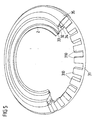
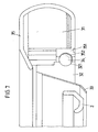
- Show here Fig. 5 to 7 first partial sectional views of the structure of the cutting device 3 with the stator 31, the rotor 32, the blade 33 and the Abstands confronter 2
- Fig. 8 a schematic diagram of the operation of the permanent magnet synchronous motor
- Fig. 9 to 12 Views of individual components of the cutting device 3.
- Fig. 5 to 7 the electric drive to a stator 31 and a rotor 32, which are arranged concentrically to each other, wherein the rotor 32 is rotatably mounted about a rotational axis A on the stator 31 via a ball bearing 34.
- the ball bearing 34 is designed as a ceramic ball bearing, in which ceramic balls are arranged rolling in grooves 321, 352 on the rotor 32 and on the stator 31 and provide a ball bearing between the rotor 32 and the stationary stator 31.
- the stator 32 is enclosed by a housing 35, which comprises the stator 31 and is only spaced over a narrow gap to the rotor 32 (see Figure 7 ).
- the stator 31 enclosing housing 35 is fixedly connected to the stator 31 and has a bearing portion 351, in which the stator-side groove 352 is formed for the ball bearing 34.
- the ball bearing 34 for rotatably supporting the rotor 32 on the stator 31 is a low-friction, almost wear-free arrangement is created, which also requires no additional lubrication. Due to the encapsulation of the stator 31 in the housing 35 and the almost gap-free termination between the housing 35 and the rotor 32, a self-contained arrangement is further created, which has minimal gaps, in which no residues of cut material can settle. In addition, since the encapsulation of the stator 31 and the rotor 32 and in particular the protected arrangement of the ball bearing 34 between the stator 31 and rotor 32 allows easy cleaning of the cutting blade, the hygienic conditions during operation of the cutting blade are significantly improved.
- the blade 33 On the inside of the rotor 32, which rotates about the axis of rotation A in the manner of an internal rotor in the operation of the cutting blade 1, the blade 33 is arranged, which has a lower section (see FIG Fig. 6 and 7 ), protrudes beyond the underside of the rotor 32 and can be brought into contact with the material to be cut for cutting the material to be cut. Radially within the blade 33 is the spacer 2 with its annular portion 22 (see for example Fig. 2 ) and has a distance to the blade 33, which defines a measure of the depth or thickness of the cut material to be cut off.
- Each tooth 310 of the stator 31 carries an armature coil 316a, 316b, 316c with each three armature windings 317, which is fed during operation of the cutting blade 1 with a time-varying sinusoidal current.
- the phase position of the current through the armature coils 316a, 316b, 316c differs here in the manner of a three-phase synchronous motor such that a rotating field is generated, which rotates about the stator 31.
- the rotary field generated in this way cooperates with the permanent magnets 324, 325 arranged on the rotor 32, which poles are reversed relative to one another, so that the north pole N of one permanent magnet 324 and the south pole S of the other permanent magnet 325 point towards the stator 31.
- the excitation field generated by the permanent magnets 324, 325 follows the rotating field generated by the armature coils 316a, 316b, 316c and thus causes a synchronous rotational movement of the rotor 32 about the rotational axis A subsequent to the rotating field of the stator 31.
- the direction of rotation of the rotating field can be selected and thus the direction of rotation of the blade can be specified.
- a direction of rotation of the blade 33 about the axis of rotation A counterclockwise be advantageous so that in operation of the Schneidemessers 1 upon contact of the cut material to be cut with the blade 33 at its front side facing away from the handle 4 (as is usually done) the cutting blade 1 experiences a force away from the user.
- a clockwise direction of rotation may be advantageous. It is also conceivable to design the direction of rotation by variable specification of the phase position switchable, so that during operation of the cutting blade 1, the direction of rotation can be changed.
- the arrangement of the permanent magnets 324, 325 on the rotor 32 and the armature coils 316 316b, 316c repeats periodically in each of the further angular sections, wherein the phase relationship of the currents in the armature coils 316a, 316b, 316c periodically corresponds.
- the number of permanent magnets used 324, 325 and armature coils 316a, 316b, 316c arbitrary, wherein in the illustrated embodiment, three armature coils 316a, 316b, 316c two permanent magnets 324, 325 are assigned.
- the number of armature coils 316a, 316b, 316c and permanent magnets 324, 325 may be selected, for example, depending on the power of the cutting blade 1 to be provided and the torque to be applied.
- FIG. 9 shows first a drawing of the stator 31 on which individual teeth 310 are formed.
- the stator 31 is formed of a plurality of layers of cut iron sheet which are stacked and form a magnetic return for the fields generated in the stator 31 and the rotor 32.
- the multilayer design of the stator 31 reduces the eddy current losses occurring in the stator 31 in a known manner.
- the armature coils 316a, 316b, 316c On the teeth 310 of the stator 31, as in Fig. 8 illustrated, the armature coils 316a, 316b, 316c arranged.
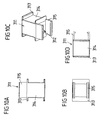
- the armature windings 317 of the armature coils 316a, 316b, 316c are arranged on bobbins 311 which are shown in individual views in FIG Fig. 10a to 10d are shown.
- the bobbins 311 have winding surfaces 314 on which the armature windings 317 are wound and on which the armature windings 317 are held by means of projections 313.
- the bobbin 311 are then inserted with the wound armature windings 317 on each tooth 310 of the stator 31, wherein the tooth 310 engages in a corresponding opening 312 of the bobbin 311 and is held on the stator 31 via a snap closure 315.
- Fig. 11a to 11d the design of the rotor 32 is shown in detail.
- the rotor 32 which is rotatably mounted on the stator 31 via the ball bearing 34, has on its radially outward-facing side a groove 321, in which the balls of the ball bearing 34 engage to support the rotor 32 on the stator 31.
- the rotor 32 is formed substantially annular and has on its inside projections 322, which, as in the enlarged detail views according to FIG Fig. 11c and 11d is shown projecting inwardly from the inside of the rotor 32 and having an inclined edge 322.
- the projections 322 on the rotor 32 are used to attach the blade 33 to the rotor 32.
- the formation of the blade 33 is in detail in Fig. 12a to 12d shown.
- the blade 33 has, for example, out Fig. 12b can be seen, an upper portion 332 of the rotor 32 abuts and a lower portion 333, which is angled relative to the upper portion 332 and sharpened to form a cutting edge.
- the lower section 333 (see FIG Fig. 1 ) from the Cutting device 3 and is brought into contact with the cutting material to be cut for cutting.
- Fig. 12a At the upper edge of the upper portion 332 of the blade 33 are, as in Fig. 12a are recesses 331 arranged, which can be brought to the attachment of the blade 33 on the rotor 32 with the projections 322 on the rotor 32 in engagement. As from the enlarged detail view according to Fig. 12c it can be seen, the recesses 331 also have an oblique edge 334, which in its slope corresponds to the slope of the edge 323 of the projections 322. For attachment of the blade 33 to the rotor 32, the blade 33 from above (see, for example Fig.
- the bevels of the edges 323, 334 on the projections 322 and the recesses 331 are such that they are formed in their slope rising against the direction of rotation of the rotor 32 and the blade 33, the recess 331 at the upper edge of the blade 33 itself So deepened-contrary to the direction of rotation of the blade 33. If the rotary blade 33 is brought into contact with the material to be cut in the feed of the cutting knife 1, the blade 33 experiences a resistance, as a result of which the blade 33 can twist slightly relative to the rotor 32.
- the protrusions 322 assigned to the recesses 331 each travel up the oblique edges 334 of the recesses 331, whereby the blade 33 is pressed into the rotor 32 and thus secured in its connection with the rotor 32.
- the connection between the blade 33 and the rotor 32 thus contracts automatically during operation of the cutting blade 1, so that a release of the connection between the blade 33 and the rotor 32 is counteracted.
- an electrical connection 41 is arranged on the handle 4 of the cutting blade 1 at the end of the handle 4 facing away from the cutting device 3, which serves for the connection of the cutting blade 1 with an external power supply unit.
- an electronic control device 42 is further arranged, which serves to power the electric drive, in particular for supplying the armature coils 316a, 316b, 316c of the stator 31 and at the same time takes over the entire control of the operation of the cutting blade 1.
- switches 51, 52 are arranged on the handle, wherein the switch 51 is arranged on the underside of the handle 4 in the vicinity of the cutting device 3 facing the end and the switch 52 on the rear, the cutting device 3 opposite end of the handle 4.
- the switches 51, 52 cooperate in such a way that for switching on the cutting blade 1, both switches 51, 52 must be actuated simultaneously. This requires that a user with one hand, the switch 51 and the other hand, the switch 52 operated so that it is impossible that a user's hand when putting the cutting blade 1 is in the cutting device 3 and thus the risk of injury a user is considerably reduced during commissioning.
- the switch 51 may be formed as microscoperüngsschalter and capacitive or detect by means of a suitable sensor, whether a user's hand is in the operation of the Schneidemessers 1 in the vicinity of the switch 51.
- the cutting blade 1 may be controlled such that the cutting blade 1 automatically shuts off as soon as the user's hand moves away from the switch 5 1. This prevents that, for example, when the user unintentionally drops the cutting blade 1, the blade 33 continues to rotate.
- the control of the switches 51, 52 can be taken over by the-arranged in the handle 4 control device 42.
- the switch 52 may be formed as a tactile and control switch, via which the speed and performance of the cutting blade 1 can be adjusted.
- the electrical supply of the cutting blade 1 is made via the electrical connection 41 provided on the handle 4. It is conceivable, for example, to connect the cutting blade 1 to an external, permanently installed supply unit, for example a transformer. It is advantageous, however, if external, portable energy storage in the form of capacitive accumulators are used for the electrical supply of the cutting blade 1, which are portable, have stored energy for the operation of the Schneidemessers 1 and after exhausting their energy reserve are rechargeable.
- FIG. 13a . 13b and 14 An embodiment of such accumulators is in Fig. 13a . 13b and 14 shown.
- an accumulator 6 is connected via a connecting line 61 to the electrical connection 41 of the cutting blade 1 and supplies this with electrical energy.
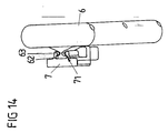
- the accumulator 6 is portable and can be worn by a user B, for example, on the belt.
- the accumulator is as in Fig. 14 is suspended via a contact device 7 on the belt of the user B, wherein the accumulator 6 is held via a plug 62 in a receptacle 71 of the contact device 7 and is electrically connected via contacts 63 to the contact device 7.
- the connecting line 61 can be inserted via a plug into the contact device 7 so as to establish the connection of the rechargeable battery 6 to the cutting blade 1.
- the charger is as in Fig. 13a is arranged in the immediate vicinity of the user's workplace B, wherein the accumulator 6 is connected to the charger via a similar contact device 7, as it is also used to connect the accumulator 6 with the Schmeidemesser 1 (see Fig. 13a with the back of the user B on a charger, not shown for charging arranged accumulators 6).
- the --Akkumulatoren 6 are advantageously capacitive and have high performance capacitors with capacities in the order of 350 Farad.
- a schematic schematic diagram of a capacitive accumulator 6 is shown in FIG Fig. 15 shown, in which capacitors C1 to C12, which are in particular designed as double-layer capacitors, are each connected in series with a resistor R1 to R12 connected in parallel and at the terminals +, - provide an output voltage which is the added voltage of the capacitances C1 to C12 corresponds.
- Such capacitive accumulators 6 offer the advantage that they allow a large number of charging cycles, for example of 500,000, require a small charging time of the order of 30 to 60 seconds and also withstand a high current impulse loading load.
- Fig. 16 shows a schematic representation of a charger 8 for charging the capacitive accumulators 6.
- the charger 8 can be designed for a continuous output power of 900W.
- the charger 8 is designed as a switching power supply, which, contrary to a classic linearly regulated power supply with transformer and longitudinally regulated power transistors on the one hand no large and heavy toroidal transformer and on the other hand no active Cooling for the removal of the resulting waste heat to the power transistors requires.
- the charger 8 is designed as a half-bridge push-pull converter with regard to its switched-mode power supply topology and has an active power factor correction (PFC).
- PFC active power factor correction
- a line filter 81 at the AC voltage input prevents high-frequency interference from the switching power supply to the network or vice versa.
- the filtered AC voltage is rectified by a rectifier 82 in the form of a diode bridge and then passes to an input stage with an active power factor correction circuit 83 which primarily provides an up-regulation of the input voltage and at the same time provides a near in-phase current to the input voltage.
- the up-regulated voltage is used to supply a DC intermediate circuit, which in turn provides the input voltage to a half-bridge push-pull converter 84 and to an auxiliary switching power supply 86. Due to the upwards regulation of the mains voltage, it is possible to operate the charger on networks with different voltages.
- the half-bridge push-pull converter 84 breaks down the DC voltage and generates a rectangular, high-frequency AC voltage, which is transmitted via a high-frequency transformer 841 to the output circuit 85 in a fixed ratio.
- the output voltage Ua which is galvanically isolated by the transformer 841, is rectified and smoothed in the output circuit 85 by a two-way rectifier 851 and a filter circuit 852.
- a pulse width modulation control circuit 88, an optocoupler 89 and a control circuit 90 are provided to control the charger 8 circuits 87 to 90 in the form of a PFC control circuit 87.
- a pulse width modulation control circuit 88, an optocoupler 89 and a control circuit 90 are provided to control the charger 8 circuits 87 to 90 in the form of a PFC control circuit 87.
- the auxiliary voltages required for the power supply of the control and monitoring circuits 87 to 90 are generated by an auxiliary switching power supply 86.
- the accumulator 6 is applied to the output terminals of the output circuit 85 and charged via the output voltage Ua.
- the charger 8 is advantageously designed to be mobile, to be carried for use at different locations and to be connected to the existing power grid on site.
- the idea underlying the invention is not limited to the embodiments described above, but can also be used in completely different embodiments.
- the invention is not limited to the use of the described electric drive in the form of a permanent-magnet synchronous motor.
- the use of the presented cutting blade is not limited to the cutting of food. It is also conceivable use of a device with a similar type of drive as a versatile food processor, with which not only food can be cut, but also the züm- stirring or mixing a mass can be used.
- the cutting blade for cutting completely different things, for example, for shearing sheep.
Landscapes
- Life Sciences & Earth Sciences (AREA)
- Forests & Forestry (AREA)
- Engineering & Computer Science (AREA)
- Mechanical Engineering (AREA)
- Food-Manufacturing Devices (AREA)
- Surgical Instruments (AREA)
- Knives (AREA)
- Sawing (AREA)
- Scissors And Nippers (AREA)
Claims (15)
- Couteau à découper, servant notamment à découper des aliments, avec- une lame disposée de manière à pouvoir tourner autour d'un axe de rotation,- un entraînement réalisé comme un moteur électrique qui présente un rotor rotatif et un stator fixe coagissant pour l'entraînement de la lame et faisant la lame en mouvement de rotation en fonctionnement du couteau à découper,caractérisé en ce que le rotor (32) peut être tourné autour de l'axe de rotation (A), est relié de manière solidaire en rotation à la lame (33) et tourne conjointement avec la lame (33) autour de l'axe de rotation (A) lorsque le couteau à découper (1) fonctionne.
- Couteau à découper selon la revendication 1, caractérisé en ce que le stator (31), le rotor (32) et la lame (33) sont réalisés de manière sensiblement annulaire et sont disposés de manière concentrique les uns par rapport aux autres.
- Couteau à découper selon la revendication 1 ou 2, caractérisé en ce que le rotor (32) est logé de manière rotative sur le stator (31) par l'intermédiaire d'un roulement à billes (34).
- Couteau à découper selon l'une quelconque des revendications précédentes, caractérisé en ce que le rotor (32) est disposé à la manière d'un rotor interne radialement dans le stator (31) et la lame (33) est disposée radialement dans le rotor (32) sur son côté intérieur.
- Couteau à découper selon l'une quelconque des revendications précédentes, caractérisé en ce que la lame (33) est maintenue positivement ou à force sur le rotor (32) pour la fixation et la liaison entre le rotor (32) et la lame (33) est détachable, sachant qu'en particulier la liaison entre le rotor (32) et la lame (33) se serre automatiquement lorsque le couteau à découper (1) fonctionne.
- Couteau à découper selon l'une quelconque des revendications précédentes, caractérisé en ce que l'entraînement (31, 32) est réalisé à la manière d'un moteur synchrone à courant triphasé à excitation permanente, sachant que sur le rotor (32) sont disposées des bobines d'induit (316a, 316b, 316c) présentant des aimants permanents et sur le stator (31) des bobines d'induit (316a, 316b, 316c) présentant des enroulements d'induit (317), lesquelles coagissent de telle manière qu'un flux de courant dû aux bobines d'induit (316a, 316b, 316c) cause un mouvement de rotation du rotor (32).
- Couteau à découper selon la revendication 6, caractérisé en ce que dans une section angulaire (α) du stator (31), à trois bobines d'induit (316a, 316b, 316c) du stator (31) sont associés deux aimants permanents (324, 325) du rotor (32), sachant notamment que- dans la section angulaire (α), les bobines d'induit (316a, 316b, 316c), en fonctionnement du couteau à découper (1), sont traversées respectivement par un courant temporairement sinusoïdal, sachant que les phases du courant se distinguent dans les bobines d'induit (316a, 316b, 316c) de la section angulaire (α) de telle manière qu'un champ magnétique rotatif se produise et- la polarité des aimants permanents (324, 325) est inversée respectivement par paires de telle manière que le pôle nord (N) d'un aimant permanent (324) et le pôle sud (S) de l'autre aimant permanent (325) soient dirigés du rotor (32) vers le stator (31) de sorte que les aimants permanents (324, 325) génèrent un champ d'excitation qui coagit avec le champ magnétique rotatif des bobines d'induit (316a, 316b, 316c) de telle manière que le rotor (31) suive le champ magnétique rotatif des bobines d'induit (316a, 316b, 316c) lorsque le couteau à découper (1) fonctionne.
- Couteau à découper selon l'une quelconque des revendications précédentes, caractérisé en ce que le stator (31) est réalisé comme un blindage magnétique et présente des dents (310) portant chacune une bobine d'induit (316a, 316b, 316c).
- Couteau à découper selon l'une quelconque des revendications précédentes, caractérisé en ce que le manche (4) du couteau à découper (1) renferme un dispositif de commande électronique (42) qui alimente les bobines d'induit (316a, 316b, 316c) du stator (31) et entreprend la commande du fonctionnement du couteau à découper (1).
- Couteau à découper selon l'une quelconque des revendications précédentes, caractérisé en ce que l'entraînement (31, 32) est enchâssé dans un boîtier (35) qui entoure l'entraînement (31, 32) au moins par section pour la protection contre les impuretés.
- Couteau à découper selon l'une quelconque des revendications précédentes, caractérisé en ce que deux commutateurs (51, 52) sont disposés pour la mise en marche du couteau à découper (1) sur le manche (4), sachant qu'un commutateur (51) se trouve sur une extrémité arrière éloignée de la lame (33) du manche (4) et l'autre commutateur (52) se trouve à un endroit espacé de l'extrémité arrière sur le manche (4) et le couteau à découper (1) ne peut être mis en marche que par un actionnement simultané des deux commutateurs (51, 52), sachant que par exemple au moins l'un des commutateurs (51) est réalisé comme un commutateur de proximité et le couteau à découper (1) ne peut être actionné que si une main d'un utilisateur se trouve à proximité du commutateur de proximité.
- Couteau à découper selon l'une quelconque des revendications précédentes, caractérisé en ce que le couteau à découper (1) présente un élément d'écartement (2) qui est relié par un dispositif de réglage (24) à la section fixe (4) du couteau à découper (1), sachant que l'élément d'écartement (2) peut être réglé à l'aide du dispositif de réglage (24) en direction de l'axe de rotation (A) par rapport à la lame (33) et est maintenu par le dispositif de réglage (24) sur la section fixe (4) du couteau à découper (1).
- Couteau à découper selon la revendication 12, caractérisé en ce que l'élément d'écartement (2) présente une section annulaire (22) qui est disposée de manière sensiblement concentrique par rapport à la lame (33) logée de manière rotative et est relié par un étrier (21) au dispositif de réglage (24) et par le dispositif de réglage (24) à la section fixe (4) du couteau à découper (1).
- Couteau à découper selon l'une quelconque des revendications précédentes, caractérisé en ce que le couteau à découper (1) peut être relié pour l'alimentation électrique à un accumulateur d'énergie (G) externe.
- Couteau à découper selon la revendication 14, caractérisé en ce que l'accumulateur d'énergie est réalisé comme un accumulateur capacitif (6) avec au moins un condensateur (C1-C12) pour l'accumulation capacitive d'énergie électrique, sachant que l'accumulateur (6) peut être porté lorsque le couteau à découper (1) fonctionne en particulier de telle manière que l'accumulateur (6) puisse être entraîné par un utilisateur (B).
Applications Claiming Priority (2)
| Application Number | Priority Date | Filing Date | Title |
|---|---|---|---|
| DE102007012287A DE102007012287A1 (de) | 2007-03-08 | 2007-03-08 | Schneidemesser, insbesondere zum Schneiden von Lebensmitteln |
| PCT/EP2008/052802 WO2008107490A1 (fr) | 2007-03-08 | 2008-03-10 | Couteau à découper, servant notamment à découper des aliments |
Publications (3)
| Publication Number | Publication Date |
|---|---|
| EP2132009A1 EP2132009A1 (fr) | 2009-12-16 |
| EP2132009B1 true EP2132009B1 (fr) | 2011-10-12 |
| EP2132009B8 EP2132009B8 (fr) | 2012-03-07 |
Family
ID=39410502
Family Applications (1)
| Application Number | Title | Priority Date | Filing Date |
|---|---|---|---|
| EP08717549A Not-in-force EP2132009B8 (fr) | 2007-03-08 | 2008-03-10 | Couteau à découper, servant notamment à découper des aliments |
Country Status (12)
| Country | Link |
|---|---|
| US (1) | US8505207B2 (fr) |
| EP (1) | EP2132009B8 (fr) |
| JP (1) | JP2010519997A (fr) |
| CN (1) | CN101663139A (fr) |
| AT (1) | ATE528113T1 (fr) |
| AU (1) | AU2008223805B2 (fr) |
| BR (1) | BRPI0808695A2 (fr) |
| CA (1) | CA2679693A1 (fr) |
| DE (2) | DE102007012287A1 (fr) |
| ES (1) | ES2375182T3 (fr) |
| RU (1) | RU2009133231A (fr) |
| WO (1) | WO2008107490A1 (fr) |
Cited By (1)
| Publication number | Priority date | Publication date | Assignee | Title |
|---|---|---|---|---|
| US20100101097A1 (en) * | 2007-03-08 | 2010-04-29 | Forschungs-Und Entwicklungsgesellschaft Fur Technische Produkte Gmbh & Co., Kg | Cutting Knife, in Particular for Cutting Food |
Families Citing this family (35)
| Publication number | Priority date | Publication date | Assignee | Title |
|---|---|---|---|---|
| US8037611B2 (en) * | 2006-06-09 | 2011-10-18 | Hantover, Inc. | Rotary knife with blade bushing |
| TWI331272B (en) * | 2007-06-29 | 2010-10-01 | Inventec Corp | Heat dissipation module |
| US8756819B2 (en) * | 2010-04-12 | 2014-06-24 | Bettcher Industries, Inc. | Power operated rotary knife with disposable blade support assembly |
| EP2502716B1 (fr) * | 2011-03-21 | 2013-11-06 | TRUMPF Werkzeugmaschinen GmbH + Co. KG | Outil pour une machine de traitement de tôle et procédé de séparation d'une feuille |
| US8726524B2 (en) | 2011-07-25 | 2014-05-20 | Bettcher Industries, Inc. | Power operated rotary knife |
| US8695222B2 (en) * | 2011-07-25 | 2014-04-15 | Bettcher Industries, Inc. | Power operated rotary knife |
| US8950076B2 (en) | 2011-07-25 | 2015-02-10 | Bettcher Industries, Inc. | Power operated rotary knife |
| US8745881B2 (en) * | 2011-07-25 | 2014-06-10 | Bettcher Industries, Inc. | Power operated rotary knife |
| US8739416B2 (en) | 2011-07-25 | 2014-06-03 | Bettcher Industries, Inc. | Power operated rotary knife |
| US8806761B2 (en) | 2011-07-25 | 2014-08-19 | Bettcher Industries, Inc. | Power operated rotary knife |
| US8752299B2 (en) * | 2012-02-29 | 2014-06-17 | Bettcher Industries, Inc. | Blade guide assembly for power operated rotary knife |
| US10039567B2 (en) * | 2012-09-07 | 2018-08-07 | Exsurco Medical, Inc. | Power operated dermatome with shielded rotary knife blade |
| US9592076B2 (en) * | 2012-09-07 | 2017-03-14 | Exsurco Medical, Inc. | Power operated dermatome with rotary knife blade |
| US10022146B2 (en) | 2015-05-29 | 2018-07-17 | Exsurco Medical, Inc. | Power operated rotary excision tool |
| US10537356B2 (en) | 2014-06-16 | 2020-01-21 | Exsurco Medical, Inc. | Power operated rotary excision tool |
| USD907205S1 (en) | 2012-09-07 | 2021-01-05 | Exsurco Medical, Inc. | Power operated rotary excision tool |
| DE102012219160A1 (de) * | 2012-10-19 | 2014-04-24 | Schmid & Wezel Gmbh & Co. | Handhaltbare Fleischerei-Maschine mit dichtem Gehäuse |
| US9522473B2 (en) * | 2013-03-14 | 2016-12-20 | Bettcher Industries, Inc. | Moveable lubrication assembly for power operated rotary knife |
| US9452541B2 (en) * | 2014-07-29 | 2016-09-27 | Bettcher Industries, Inc. | Power operated rotary knife with vacuum attachment assembly |
| US9999986B2 (en) * | 2014-07-29 | 2018-06-19 | Bettcher Industries, Inc. | Power operated rotary knife with vacuum attachment assembly |
| US9579810B2 (en) * | 2014-07-29 | 2017-02-28 | Bettcher Industries, Inc. | Power operated rotary knife with vacuum attachment assembly |
| US10011035B2 (en) * | 2015-02-23 | 2018-07-03 | Makita Corporation | Machining device and electric motor for the same |
| IN2015CH03126A (fr) * | 2015-06-22 | 2015-07-10 | Wipro Ltd | |
| US10343296B2 (en) | 2015-07-25 | 2019-07-09 | Bettcher Industries, Inc. | Power operated rotary knife with notched rotary knife blade and trim guide |
| US9833919B2 (en) | 2015-10-02 | 2017-12-05 | Bettcher Industries, Inc. | Power operated rotary knife |
| CN105815359A (zh) * | 2016-04-26 | 2016-08-03 | 闫爱军 | 一种切面刀 |
| US10786919B2 (en) * | 2016-08-18 | 2020-09-29 | Hantover, Inc. | Eccentric blade housing for rotary knife |
| US10471614B2 (en) | 2016-12-09 | 2019-11-12 | Bettcher Industries, Inc. | Cam-actuated split blade housing for power operated rotary knife |
| US10124500B2 (en) * | 2016-12-09 | 2018-11-13 | Bettcher Industries, Inc. | Cam-actuated split blade housing for power operated rotary knife |
| US10040211B2 (en) | 2016-12-09 | 2018-08-07 | Bettcher Industries, Inc. | Power operated rotary knife |
| USD973115S1 (en) | 2018-01-26 | 2022-12-20 | Bettcher Industries, Inc. | Annular blade |
| USD1094052S1 (en) | 2016-12-09 | 2025-09-23 | Bettcher Industries, Inc. | Annular blade |
| US10830468B2 (en) * | 2017-06-21 | 2020-11-10 | Air Distribution Technologies Ip, Llc | HVAC scrubber unit mechanical improvement systems and methods |
| USD912489S1 (en) | 2019-06-13 | 2021-03-09 | Bettcher Industries, Inc. | Housing for a power operated rotary knife |
| US11077571B2 (en) | 2019-10-02 | 2021-08-03 | Bettcher Industries, Inc. | Split blade housing with expansion sleeve assembly for power operated rotary knife |
Family Cites Families (36)
| Publication number | Priority date | Publication date | Assignee | Title |
|---|---|---|---|---|
| USRE25947E (en) * | 1965-12-14 | Trimming and slicing device | ||
| US1648931A (en) * | 1927-01-20 | 1927-11-15 | Gen Seafoods Corp | Trimming tool |
| US3150409A (en) * | 1963-04-10 | 1964-09-29 | Frederick F Wilcox | Dehairing and skinning device |
| US4178683A (en) * | 1978-07-17 | 1979-12-18 | Bettcher Industries, Inc. | Knife with removable blade |
| US4198750A (en) * | 1978-10-16 | 1980-04-22 | Bettcher Industries, Inc. | Ring blade knife having wear plate |
| US4363170A (en) * | 1980-11-03 | 1982-12-14 | Mccullough Timothy J | Blade holder for meat trimming knife |
| US4439924A (en) * | 1981-11-05 | 1984-04-03 | Bettcher Industries, Inc. | Rotary hand knife |
| US4637140A (en) * | 1981-12-14 | 1987-01-20 | Bettcher Industries, Inc. | Boning and trimming knife |
| US4494311A (en) * | 1982-10-13 | 1985-01-22 | Mccullough Timothy J | Meat trimming knife |
| US4575938A (en) * | 1984-07-12 | 1986-03-18 | Mccullough Timothy J | Meat trimming knife |
| US4575937A (en) * | 1984-10-22 | 1986-03-18 | Mccullough Timothy J | Depth control gauge for meat trimming knife |
| US4854046A (en) * | 1987-10-07 | 1989-08-08 | Bettcher Industries, Inc. | Rotary hand trimming knife |
| US4942665A (en) * | 1989-09-19 | 1990-07-24 | Mccullough Timothy J | Meat trimming knife and drive system therefore |
| JPH0439447A (ja) * | 1990-06-05 | 1992-02-10 | Matsuura Sangyo Kk | 環状歯車による動力伝達機構及び環状歯車による動力伝達機構を用いた刈払機 |
| US5230154A (en) | 1990-09-28 | 1993-07-27 | Bettcher Industries, Inc. | Modular power-driven rotary knife, improved handle and method |
| WO1993008001A1 (fr) * | 1991-10-25 | 1993-04-29 | Reserwa Ag | Fraiseuse type chaine a anneaux mus vers l'avant et dans des sens de rotation contraires |
| US5522142A (en) * | 1994-06-30 | 1996-06-04 | Bettcher Industries, Inc. | Rotary knife and slicing gauge |
| US5623764A (en) * | 1995-05-30 | 1997-04-29 | Cseh; Ferenc | Hair clipper |
| US5664332A (en) * | 1996-02-14 | 1997-09-09 | Bettcher Industries, Inc. | Hand knife with cover |
| US5692307A (en) * | 1996-06-28 | 1997-12-02 | Bettcher Industries, Inc. | Rotary knife blade |
| US5761817A (en) * | 1996-10-17 | 1998-06-09 | Bettcher Industries, Inc. | Rotary hand knife |
| TW393291B (en) * | 1997-07-14 | 2000-06-11 | Itoh Electric Co Ltd | Mowing machine |
| US6769184B1 (en) * | 1998-07-22 | 2004-08-03 | Bettcher Industries, Inc. | Low friction rotary knife |
| US6655033B2 (en) * | 2001-10-16 | 2003-12-02 | Bettcher Indusrties, Inc. | Pneumatic hand tool with improved control valve |
| US6615494B2 (en) * | 2002-01-15 | 2003-09-09 | John W. Long | Boning and defatting rotary knife |
| US6662452B2 (en) * | 2002-04-22 | 2003-12-16 | Bettcher Industries, Inc. | Power operated rotary knife |
| CN1681629A (zh) * | 2002-09-06 | 2005-10-12 | 貝特彻工业公司 | 用于圆盘刀具的低成本的环形刀片 |
| ITMO20020320A1 (it) * | 2002-11-06 | 2004-05-07 | Lgr Equipment Di Graziano Roncaglia | Utensile per coltelli rotanti. |
| US7140112B2 (en) * | 2003-08-22 | 2006-11-28 | Jeg, Inc. | Head cover trimming system |
| US7207114B2 (en) * | 2004-08-19 | 2007-04-24 | Bettcher Industries, Inc. | Rotary knife with improved drive transmission |
| US8037611B2 (en) * | 2006-06-09 | 2011-10-18 | Hantover, Inc. | Rotary knife with blade bushing |
| US20070283573A1 (en) * | 2006-06-09 | 2007-12-13 | Hantover, Inc. | Rotary knife with blade bushing |
| US8661692B2 (en) * | 2006-10-27 | 2014-03-04 | Bettcher Industries, Inc. | Split blade housing for power operated rotary knife |
| DE102007012287A1 (de) * | 2007-03-08 | 2008-09-11 | Forschungs- und Entwicklungsgesellschaft für technische Produkte mbH & Co. KG | Schneidemesser, insbesondere zum Schneiden von Lebensmitteln |
| US8250766B2 (en) * | 2009-01-07 | 2012-08-28 | Hantover, Inc. | Safety release for direct drive of rotary knife |
| US8448340B2 (en) * | 2010-02-01 | 2013-05-28 | Bettcher Industries, Inc. | Large diameter notched blade and blade housing for power operated rotary knife |
-
2007
- 2007-03-08 DE DE102007012287A patent/DE102007012287A1/de not_active Withdrawn
- 2007-03-08 DE DE202007018892U patent/DE202007018892U1/de not_active Expired - Lifetime
-
2008
- 2008-03-10 AT AT08717549T patent/ATE528113T1/de active
- 2008-03-10 CN CN200880007598A patent/CN101663139A/zh active Pending
- 2008-03-10 EP EP08717549A patent/EP2132009B8/fr not_active Not-in-force
- 2008-03-10 CA CA002679693A patent/CA2679693A1/fr not_active Abandoned
- 2008-03-10 ES ES08717549T patent/ES2375182T3/es active Active
- 2008-03-10 BR BRPI0808695-8A patent/BRPI0808695A2/pt not_active IP Right Cessation
- 2008-03-10 WO PCT/EP2008/052802 patent/WO2008107490A1/fr not_active Ceased
- 2008-03-10 JP JP2009552219A patent/JP2010519997A/ja active Pending
- 2008-03-10 US US12/528,834 patent/US8505207B2/en not_active Expired - Fee Related
- 2008-03-10 RU RU2009133231/02A patent/RU2009133231A/ru unknown
- 2008-03-10 AU AU2008223805A patent/AU2008223805B2/en not_active Ceased
Cited By (2)
| Publication number | Priority date | Publication date | Assignee | Title |
|---|---|---|---|---|
| US20100101097A1 (en) * | 2007-03-08 | 2010-04-29 | Forschungs-Und Entwicklungsgesellschaft Fur Technische Produkte Gmbh & Co., Kg | Cutting Knife, in Particular for Cutting Food |
| US8505207B2 (en) * | 2007-03-08 | 2013-08-13 | Forschungs- und Entwicklungsgesellschaft für technische Produckte GmbH & Co. KG | Cutting knife, in particular for cutting food |
Also Published As
| Publication number | Publication date |
|---|---|
| EP2132009A1 (fr) | 2009-12-16 |
| CN101663139A (zh) | 2010-03-03 |
| ATE528113T1 (de) | 2011-10-15 |
| BRPI0808695A2 (pt) | 2014-09-02 |
| RU2009133231A (ru) | 2011-04-20 |
| ES2375182T3 (es) | 2012-02-27 |
| DE202007018892U1 (de) | 2009-10-01 |
| EP2132009B8 (fr) | 2012-03-07 |
| DE102007012287A1 (de) | 2008-09-11 |
| AU2008223805A1 (en) | 2008-09-12 |
| CA2679693A1 (fr) | 2008-09-12 |
| JP2010519997A (ja) | 2010-06-10 |
| US8505207B2 (en) | 2013-08-13 |
| WO2008107490A1 (fr) | 2008-09-12 |
| US20100101097A1 (en) | 2010-04-29 |
| AU2008223805B2 (en) | 2014-07-17 |
Similar Documents
| Publication | Publication Date | Title |
|---|---|---|
| EP2132009B1 (fr) | Couteau à découper, servant notamment à découper des aliments | |
| DE112009005302B4 (de) | Rotierende elektrische Maschinenvorrichtung | |
| EP2342148B1 (fr) | Entraînement de rouleaux et système d entraînements de rouleaux | |
| EP2426815B1 (fr) | Entraînement électrique | |
| DE2949172A1 (de) | Drehzahlgeregelter elektromotor | |
| EP2541755A1 (fr) | Dispositif d'entraînement pour un véhicule | |
| EP2681840A1 (fr) | Entraînement électrique | |
| EP4066356A1 (fr) | Rotor pour une machine électrique et procédé de production d'un rotor | |
| EP2934817A1 (fr) | Machine-outil portative pourvue d'un moteur électrique à commutation électronique et d'une électronique intégrée | |
| WO2022175047A1 (fr) | Dispositif de commutation pour un moteur électrique pouvant fonctionner sélectivement avec au moins deux tensions d'alimentation différentes et outil électrique pourvu d'un dispositif de commutation | |
| DE10008451A1 (de) | Schubkarren mit einem elektrischen Antrieb zur Schubkraftunterstützung | |
| DE102013018716A1 (de) | Fitnessgerät oder Nachrüstsatz für ein Fitnessgerät zur professionellen Stromgewinnung | |
| DE102018203566B4 (de) | Elektromechanischer Energiewandler mit einem inneren und einem äußeren Energiewandler | |
| EP2551999A1 (fr) | Machine électrique dotée d'une excitation sans anneau abrasif | |
| DE202013010116U1 (de) | Fitnessgerät oder Nachrüstsatz für ein Fitnessgerät zur professionellen Stromgewinnung | |
| EP2875569A2 (fr) | Dispositif pour la production de courant sans contact | |
| EP1114989A2 (fr) | Dispositif pour mesurer un deséquilibre de rotor | |
| DE1268262B (de) | Einphasenwechselstrommotor, insbesondere fuer Betriebsstroeme hoeherer Frequenz | |
| DE3317129C2 (de) | Magnetisches Getriebe | |
| EP1758229B1 (fr) | Moteur électrique | |
| CH387160A (de) | Elektrischer Lüfterantrieb für eine elektrische Maschine | |
| DE1538831C (de) | Elektromotor mit veränderlichem magnetischem Widerstand | |
| DE3220011A1 (de) | Kutter zum schneiden und mischen von fleisch oder aehnlichen stoffen | |
| DE255063C (fr) | ||
| EP4320710A1 (fr) | Outil électrique pouvant fonctionner sélectivement avec au moins deux tensions d'alimentation différentes |
Legal Events
| Date | Code | Title | Description |
|---|---|---|---|
| PUAI | Public reference made under article 153(3) epc to a published international application that has entered the european phase |
Free format text: ORIGINAL CODE: 0009012 |
|
| 17P | Request for examination filed |
Effective date: 20090930 |
|
| AK | Designated contracting states |
Kind code of ref document: A1 Designated state(s): AT BE BG CH CY CZ DE DK EE ES FI FR GB GR HR HU IE IS IT LI LT LU LV MC MT NL NO PL PT RO SE SI SK TR |
|
| DAX | Request for extension of the european patent (deleted) | ||
| GRAP | Despatch of communication of intention to grant a patent |
Free format text: ORIGINAL CODE: EPIDOSNIGR1 |
|
| RIN1 | Information on inventor provided before grant (corrected) |
Inventor name: THIEN, GERHARD |
|
| GRAS | Grant fee paid |
Free format text: ORIGINAL CODE: EPIDOSNIGR3 |
|
| GRAA | (expected) grant |
Free format text: ORIGINAL CODE: 0009210 |
|
| AK | Designated contracting states |
Kind code of ref document: B1 Designated state(s): AT BE BG CH CY CZ DE DK EE ES FI FR GB GR HR HU IE IS IT LI LT LU LV MC MT NL NO PL PT RO SE SI SK TR |
|
| REG | Reference to a national code |
Ref country code: GB Ref legal event code: FG4D Free format text: NOT ENGLISH |
|
| REG | Reference to a national code |
Ref country code: CH Ref legal event code: EP |
|
| REG | Reference to a national code |
Ref country code: IE Ref legal event code: FG4D |
|
| REG | Reference to a national code |
Ref country code: DE Ref legal event code: R096 Ref document number: 502008005162 Country of ref document: DE Effective date: 20111208 |
|
| RAP2 | Party data changed (patent owner data changed or rights of a patent transferred) |
Owner name: ROTOTOR AG |
|
| REG | Reference to a national code |
Ref country code: CH Ref legal event code: NV Representative=s name: SCHMAUDER & PARTNER AG PATENT- UND MARKENANWAELTE |
|
| REG | Reference to a national code |
Ref country code: NL Ref legal event code: VDEP Effective date: 20111012 |
|
| REG | Reference to a national code |
Ref country code: DE Ref legal event code: R082 Ref document number: 502008005162 Country of ref document: DE Representative=s name: MAIKOWSKI & NINNEMANN PATENTANWAELTE, DE Ref country code: DE Ref legal event code: R082 Ref document number: 502008005162 Country of ref document: DE Representative=s name: MAIKOWSKI & NINNEMANN PATENTANWAELTE PARTNERSC, DE |
|
| REG | Reference to a national code |
Ref country code: ES Ref legal event code: FG2A Ref document number: 2375182 Country of ref document: ES Kind code of ref document: T3 Effective date: 20120227 |
|
| REG | Reference to a national code |
Ref country code: GB Ref legal event code: 732E Free format text: REGISTERED BETWEEN 20120216 AND 20120222 |
|
| LTIE | Lt: invalidation of european patent or patent extension |
Effective date: 20111012 |
|
| PG25 | Lapsed in a contracting state [announced via postgrant information from national office to epo] |
Ref country code: LT Free format text: LAPSE BECAUSE OF FAILURE TO SUBMIT A TRANSLATION OF THE DESCRIPTION OR TO PAY THE FEE WITHIN THE PRESCRIBED TIME-LIMIT Effective date: 20111012 Ref country code: IS Free format text: LAPSE BECAUSE OF FAILURE TO SUBMIT A TRANSLATION OF THE DESCRIPTION OR TO PAY THE FEE WITHIN THE PRESCRIBED TIME-LIMIT Effective date: 20120212 Ref country code: NO Free format text: LAPSE BECAUSE OF FAILURE TO SUBMIT A TRANSLATION OF THE DESCRIPTION OR TO PAY THE FEE WITHIN THE PRESCRIBED TIME-LIMIT Effective date: 20120112 |
|
| REG | Reference to a national code |
Ref country code: IE Ref legal event code: FD4D |
|
| PG25 | Lapsed in a contracting state [announced via postgrant information from national office to epo] |
Ref country code: PT Free format text: LAPSE BECAUSE OF FAILURE TO SUBMIT A TRANSLATION OF THE DESCRIPTION OR TO PAY THE FEE WITHIN THE PRESCRIBED TIME-LIMIT Effective date: 20120213 Ref country code: NL Free format text: LAPSE BECAUSE OF FAILURE TO SUBMIT A TRANSLATION OF THE DESCRIPTION OR TO PAY THE FEE WITHIN THE PRESCRIBED TIME-LIMIT Effective date: 20111012 Ref country code: GR Free format text: LAPSE BECAUSE OF FAILURE TO SUBMIT A TRANSLATION OF THE DESCRIPTION OR TO PAY THE FEE WITHIN THE PRESCRIBED TIME-LIMIT Effective date: 20120113 Ref country code: LV Free format text: LAPSE BECAUSE OF FAILURE TO SUBMIT A TRANSLATION OF THE DESCRIPTION OR TO PAY THE FEE WITHIN THE PRESCRIBED TIME-LIMIT Effective date: 20111012 Ref country code: HR Free format text: LAPSE BECAUSE OF FAILURE TO SUBMIT A TRANSLATION OF THE DESCRIPTION OR TO PAY THE FEE WITHIN THE PRESCRIBED TIME-LIMIT Effective date: 20111012 Ref country code: SE Free format text: LAPSE BECAUSE OF FAILURE TO SUBMIT A TRANSLATION OF THE DESCRIPTION OR TO PAY THE FEE WITHIN THE PRESCRIBED TIME-LIMIT Effective date: 20111012 Ref country code: SI Free format text: LAPSE BECAUSE OF FAILURE TO SUBMIT A TRANSLATION OF THE DESCRIPTION OR TO PAY THE FEE WITHIN THE PRESCRIBED TIME-LIMIT Effective date: 20111012 |
|
| PG25 | Lapsed in a contracting state [announced via postgrant information from national office to epo] |
Ref country code: CY Free format text: LAPSE BECAUSE OF FAILURE TO SUBMIT A TRANSLATION OF THE DESCRIPTION OR TO PAY THE FEE WITHIN THE PRESCRIBED TIME-LIMIT Effective date: 20111012 |
|
| PG25 | Lapsed in a contracting state [announced via postgrant information from national office to epo] |
Ref country code: EE Free format text: LAPSE BECAUSE OF FAILURE TO SUBMIT A TRANSLATION OF THE DESCRIPTION OR TO PAY THE FEE WITHIN THE PRESCRIBED TIME-LIMIT Effective date: 20111012 Ref country code: DK Free format text: LAPSE BECAUSE OF FAILURE TO SUBMIT A TRANSLATION OF THE DESCRIPTION OR TO PAY THE FEE WITHIN THE PRESCRIBED TIME-LIMIT Effective date: 20111012 Ref country code: SK Free format text: LAPSE BECAUSE OF FAILURE TO SUBMIT A TRANSLATION OF THE DESCRIPTION OR TO PAY THE FEE WITHIN THE PRESCRIBED TIME-LIMIT Effective date: 20111012 Ref country code: BG Free format text: LAPSE BECAUSE OF FAILURE TO SUBMIT A TRANSLATION OF THE DESCRIPTION OR TO PAY THE FEE WITHIN THE PRESCRIBED TIME-LIMIT Effective date: 20120112 Ref country code: IE Free format text: LAPSE BECAUSE OF FAILURE TO SUBMIT A TRANSLATION OF THE DESCRIPTION OR TO PAY THE FEE WITHIN THE PRESCRIBED TIME-LIMIT Effective date: 20111012 Ref country code: CZ Free format text: LAPSE BECAUSE OF FAILURE TO SUBMIT A TRANSLATION OF THE DESCRIPTION OR TO PAY THE FEE WITHIN THE PRESCRIBED TIME-LIMIT Effective date: 20111012 |
|
| PLBE | No opposition filed within time limit |
Free format text: ORIGINAL CODE: 0009261 |
|
| STAA | Information on the status of an ep patent application or granted ep patent |
Free format text: STATUS: NO OPPOSITION FILED WITHIN TIME LIMIT |
|
| PG25 | Lapsed in a contracting state [announced via postgrant information from national office to epo] |
Ref country code: RO Free format text: LAPSE BECAUSE OF FAILURE TO SUBMIT A TRANSLATION OF THE DESCRIPTION OR TO PAY THE FEE WITHIN THE PRESCRIBED TIME-LIMIT Effective date: 20111012 Ref country code: PL Free format text: LAPSE BECAUSE OF FAILURE TO SUBMIT A TRANSLATION OF THE DESCRIPTION OR TO PAY THE FEE WITHIN THE PRESCRIBED TIME-LIMIT Effective date: 20111012 |
|
| 26N | No opposition filed |
Effective date: 20120713 |
|
| BERE | Be: lapsed |
Owner name: ROTOR AG Effective date: 20120331 |
|
| REG | Reference to a national code |
Ref country code: DE Ref legal event code: R097 Ref document number: 502008005162 Country of ref document: DE Effective date: 20120713 |
|
| PG25 | Lapsed in a contracting state [announced via postgrant information from national office to epo] |
Ref country code: BE Free format text: LAPSE BECAUSE OF NON-PAYMENT OF DUE FEES Effective date: 20120331 |
|
| PGFP | Annual fee paid to national office [announced via postgrant information from national office to epo] |
Ref country code: MC Payment date: 20130319 Year of fee payment: 6 Ref country code: LU Payment date: 20130320 Year of fee payment: 6 Ref country code: CH Payment date: 20130319 Year of fee payment: 6 |
|
| PG25 | Lapsed in a contracting state [announced via postgrant information from national office to epo] |
Ref country code: FI Free format text: LAPSE BECAUSE OF FAILURE TO SUBMIT A TRANSLATION OF THE DESCRIPTION OR TO PAY THE FEE WITHIN THE PRESCRIBED TIME-LIMIT Effective date: 20111012 |
|
| PGFP | Annual fee paid to national office [announced via postgrant information from national office to epo] |
Ref country code: AT Payment date: 20130318 Year of fee payment: 6 |
|
| PG25 | Lapsed in a contracting state [announced via postgrant information from national office to epo] |
Ref country code: MT Free format text: LAPSE BECAUSE OF FAILURE TO SUBMIT A TRANSLATION OF THE DESCRIPTION OR TO PAY THE FEE WITHIN THE PRESCRIBED TIME-LIMIT Effective date: 20111012 |
|
| PG25 | Lapsed in a contracting state [announced via postgrant information from national office to epo] |
Ref country code: TR Free format text: LAPSE BECAUSE OF FAILURE TO SUBMIT A TRANSLATION OF THE DESCRIPTION OR TO PAY THE FEE WITHIN THE PRESCRIBED TIME-LIMIT Effective date: 20111012 |
|
| PGFP | Annual fee paid to national office [announced via postgrant information from national office to epo] |
Ref country code: IT Payment date: 20140326 Year of fee payment: 7 Ref country code: ES Payment date: 20140324 Year of fee payment: 7 Ref country code: FR Payment date: 20140319 Year of fee payment: 7 |
|
| PGFP | Annual fee paid to national office [announced via postgrant information from national office to epo] |
Ref country code: GB Payment date: 20140324 Year of fee payment: 7 |
|
| PG25 | Lapsed in a contracting state [announced via postgrant information from national office to epo] |
Ref country code: HU Free format text: LAPSE BECAUSE OF FAILURE TO SUBMIT A TRANSLATION OF THE DESCRIPTION OR TO PAY THE FEE WITHIN THE PRESCRIBED TIME-LIMIT Effective date: 20080310 |
|
| PG25 | Lapsed in a contracting state [announced via postgrant information from national office to epo] |
Ref country code: LU Free format text: LAPSE BECAUSE OF NON-PAYMENT OF DUE FEES Effective date: 20140310 |
|
| REG | Reference to a national code |
Ref country code: CH Ref legal event code: PL |
|
| REG | Reference to a national code |
Ref country code: AT Ref legal event code: MM01 Ref document number: 528113 Country of ref document: AT Kind code of ref document: T Effective date: 20140310 |
|
| PG25 | Lapsed in a contracting state [announced via postgrant information from national office to epo] |
Ref country code: LI Free format text: LAPSE BECAUSE OF NON-PAYMENT OF DUE FEES Effective date: 20140331 Ref country code: CH Free format text: LAPSE BECAUSE OF NON-PAYMENT OF DUE FEES Effective date: 20140331 |
|
| PG25 | Lapsed in a contracting state [announced via postgrant information from national office to epo] |
Ref country code: AT Free format text: LAPSE BECAUSE OF NON-PAYMENT OF DUE FEES Effective date: 20140310 |
|
| GBPC | Gb: european patent ceased through non-payment of renewal fee |
Effective date: 20150310 |
|
| PG25 | Lapsed in a contracting state [announced via postgrant information from national office to epo] |
Ref country code: IT Free format text: LAPSE BECAUSE OF NON-PAYMENT OF DUE FEES Effective date: 20150310 |
|
| REG | Reference to a national code |
Ref country code: FR Ref legal event code: ST Effective date: 20151130 |
|
| PG25 | Lapsed in a contracting state [announced via postgrant information from national office to epo] |
Ref country code: GB Free format text: LAPSE BECAUSE OF NON-PAYMENT OF DUE FEES Effective date: 20150310 |
|
| PG25 | Lapsed in a contracting state [announced via postgrant information from national office to epo] |
Ref country code: FR Free format text: LAPSE BECAUSE OF NON-PAYMENT OF DUE FEES Effective date: 20150331 |
|
| REG | Reference to a national code |
Ref country code: ES Ref legal event code: FD2A Effective date: 20160426 |
|
| PG25 | Lapsed in a contracting state [announced via postgrant information from national office to epo] |
Ref country code: MC Free format text: LAPSE BECAUSE OF NON-PAYMENT OF DUE FEES Effective date: 20140331 |
|
| PG25 | Lapsed in a contracting state [announced via postgrant information from national office to epo] |
Ref country code: ES Free format text: LAPSE BECAUSE OF NON-PAYMENT OF DUE FEES Effective date: 20150311 |
|
| PGFP | Annual fee paid to national office [announced via postgrant information from national office to epo] |
Ref country code: DE Payment date: 20180322 Year of fee payment: 11 |
|
| REG | Reference to a national code |
Ref country code: DE Ref legal event code: R119 Ref document number: 502008005162 Country of ref document: DE |
|
| PG25 | Lapsed in a contracting state [announced via postgrant information from national office to epo] |
Ref country code: DE Free format text: LAPSE BECAUSE OF NON-PAYMENT OF DUE FEES Effective date: 20191001 |