EP2132608B1 - Procédé et dispositif de commande de robots pour le soudage de pièces - Google Patents
Procédé et dispositif de commande de robots pour le soudage de pièces Download PDFInfo
- Publication number
- EP2132608B1 EP2132608B1 EP08716141.0A EP08716141A EP2132608B1 EP 2132608 B1 EP2132608 B1 EP 2132608B1 EP 08716141 A EP08716141 A EP 08716141A EP 2132608 B1 EP2132608 B1 EP 2132608B1
- Authority
- EP
- European Patent Office
- Prior art keywords
- profiles
- workpiece
- dimensional
- plate
- pixels
- Prior art date
- Legal status (The legal status is an assumption and is not a legal conclusion. Google has not performed a legal analysis and makes no representation as to the accuracy of the status listed.)
- Active
Links
Images

Classifications
-
- G—PHYSICS
- G05—CONTROLLING; REGULATING
- G05B—CONTROL OR REGULATING SYSTEMS IN GENERAL; FUNCTIONAL ELEMENTS OF SUCH SYSTEMS; MONITORING OR TESTING ARRANGEMENTS FOR SUCH SYSTEMS OR ELEMENTS
- G05B19/00—Program-control systems
- G05B19/02—Program-control systems electric
- G05B19/42—Recording and playback systems, i.e. in which the program is recorded from a cycle of operations, e.g. the cycle of operations being manually controlled, after which this record is played back on the same machine
-
- G—PHYSICS
- G05—CONTROLLING; REGULATING
- G05B—CONTROL OR REGULATING SYSTEMS IN GENERAL; FUNCTIONAL ELEMENTS OF SUCH SYSTEMS; MONITORING OR TESTING ARRANGEMENTS FOR SUCH SYSTEMS OR ELEMENTS
- G05B19/00—Program-control systems
- G05B19/02—Program-control systems electric
- G05B19/42—Recording and playback systems, i.e. in which the program is recorded from a cycle of operations, e.g. the cycle of operations being manually controlled, after which this record is played back on the same machine
- G05B19/4202—Recording and playback systems, i.e. in which the program is recorded from a cycle of operations, e.g. the cycle of operations being manually controlled, after which this record is played back on the same machine preparation of the program medium using a drawing, a model
- G05B19/4207—Recording and playback systems, i.e. in which the program is recorded from a cycle of operations, e.g. the cycle of operations being manually controlled, after which this record is played back on the same machine preparation of the program medium using a drawing, a model in which a model is traced or scanned and corresponding data recorded
-
- B—PERFORMING OPERATIONS; TRANSPORTING
- B23—MACHINE TOOLS; METAL-WORKING NOT OTHERWISE PROVIDED FOR
- B23K—SOLDERING OR UNSOLDERING; WELDING; CLADDING OR PLATING BY SOLDERING OR WELDING; CUTTING BY APPLYING HEAT LOCALLY, e.g. FLAME CUTTING; WORKING BY LASER BEAM
- B23K31/00—Processes relevant to this subclass, specially adapted for particular articles or purposes, but not covered by any single one of main groups B23K1/00 - B23K28/00
- B23K31/02—Processes relevant to this subclass, specially adapted for particular articles or purposes, but not covered by any single one of main groups B23K1/00 - B23K28/00 relating to soldering or welding
-
- B—PERFORMING OPERATIONS; TRANSPORTING
- B23—MACHINE TOOLS; METAL-WORKING NOT OTHERWISE PROVIDED FOR
- B23K—SOLDERING OR UNSOLDERING; WELDING; CLADDING OR PLATING BY SOLDERING OR WELDING; CUTTING BY APPLYING HEAT LOCALLY, e.g. FLAME CUTTING; WORKING BY LASER BEAM
- B23K9/00—Arc welding or cutting
- B23K9/02—Seam welding; Backing means; Inserts
- B23K9/025—Seam welding; Backing means; Inserts for rectilinear seams
- B23K9/0256—Seam welding; Backing means; Inserts for rectilinear seams for welding ribs on plates
-
- G—PHYSICS
- G01—MEASURING; TESTING
- G01B—MEASURING LENGTH, THICKNESS OR SIMILAR LINEAR DIMENSIONS; MEASURING ANGLES; MEASURING AREAS; MEASURING IRREGULARITIES OF SURFACES OR CONTOURS
- G01B11/00—Measuring arrangements characterised by the use of optical techniques
- G01B11/24—Measuring arrangements characterised by the use of optical techniques for measuring contours or curvatures
- G01B11/25—Measuring arrangements characterised by the use of optical techniques for measuring contours or curvatures by projecting a pattern, e.g. one or more lines, moiré fringes on the object
- G01B11/2518—Projection by scanning of the object
-
- G—PHYSICS
- G01—MEASURING; TESTING
- G01B—MEASURING LENGTH, THICKNESS OR SIMILAR LINEAR DIMENSIONS; MEASURING ANGLES; MEASURING AREAS; MEASURING IRREGULARITIES OF SURFACES OR CONTOURS
- G01B21/00—Measuring arrangements or details thereof, where the measuring technique is not covered by the other groups of this subclass, unspecified or not relevant
- G01B21/02—Measuring arrangements or details thereof, where the measuring technique is not covered by the other groups of this subclass, unspecified or not relevant for measuring length, width, or thickness
- G01B21/04—Measuring arrangements or details thereof, where the measuring technique is not covered by the other groups of this subclass, unspecified or not relevant for measuring length, width, or thickness by measuring coordinates of points
- G01B21/042—Calibration or calibration artifacts
-
- G—PHYSICS
- G06—COMPUTING OR CALCULATING; COUNTING
- G06T—IMAGE DATA PROCESSING OR GENERATION, IN GENERAL
- G06T7/00—Image analysis
- G06T7/50—Depth or shape recovery
- G06T7/521—Depth or shape recovery from laser ranging, e.g. using interferometry; from the projection of structured light
-
- G—PHYSICS
- G05—CONTROLLING; REGULATING
- G05B—CONTROL OR REGULATING SYSTEMS IN GENERAL; FUNCTIONAL ELEMENTS OF SUCH SYSTEMS; MONITORING OR TESTING ARRANGEMENTS FOR SUCH SYSTEMS OR ELEMENTS
- G05B2219/00—Program-control systems
- G05B2219/30—Nc systems
- G05B2219/36—Nc in input of data, input key till input tape
- G05B2219/36248—Generate automatically machining, stitching points from scanned contour
-
- G—PHYSICS
- G05—CONTROLLING; REGULATING
- G05B—CONTROL OR REGULATING SYSTEMS IN GENERAL; FUNCTIONAL ELEMENTS OF SUCH SYSTEMS; MONITORING OR TESTING ARRANGEMENTS FOR SUCH SYSTEMS OR ELEMENTS
- G05B2219/00—Program-control systems
- G05B2219/30—Nc systems
- G05B2219/37—Measurements
- G05B2219/37009—Calibration of vision system, camera, adapt light level
-
- G—PHYSICS
- G05—CONTROLLING; REGULATING
- G05B—CONTROL OR REGULATING SYSTEMS IN GENERAL; FUNCTIONAL ELEMENTS OF SUCH SYSTEMS; MONITORING OR TESTING ARRANGEMENTS FOR SUCH SYSTEMS OR ELEMENTS
- G05B2219/00—Program-control systems
- G05B2219/30—Nc systems
- G05B2219/37—Measurements
- G05B2219/37555—Camera detects orientation, position workpiece, points of workpiece
-
- G—PHYSICS
- G05—CONTROLLING; REGULATING
- G05B—CONTROL OR REGULATING SYSTEMS IN GENERAL; FUNCTIONAL ELEMENTS OF SUCH SYSTEMS; MONITORING OR TESTING ARRANGEMENTS FOR SUCH SYSTEMS OR ELEMENTS
- G05B2219/00—Program-control systems
- G05B2219/30—Nc systems
- G05B2219/37—Measurements
- G05B2219/37567—3-D vision, stereo vision, with two cameras
-
- G—PHYSICS
- G05—CONTROLLING; REGULATING
- G05B—CONTROL OR REGULATING SYSTEMS IN GENERAL; FUNCTIONAL ELEMENTS OF SUCH SYSTEMS; MONITORING OR TESTING ARRANGEMENTS FOR SUCH SYSTEMS OR ELEMENTS
- G05B2219/00—Program-control systems
- G05B2219/30—Nc systems
- G05B2219/45—Nc applications
- G05B2219/45104—Lasrobot, welding robot
Definitions
- the invention relates to a method for controlling robots for welding three-dimensional workpieces.
- micropanels which consist of steel plates and stiffening profiles welded to them.
- these reinforcing profiles of different types are stapled to the steel plates and then welded with articulated robots or portal welding machines.
- the profiles are characterized by different profile shapes, dimensions and Endbetree, the arrangement of the profiles on the plates is possible in any way.
- the movement programming of the welding robots for web welding is disproportionate, especially in the case of small quantities, as is the case with the micropanels in shipbuilding high expenditure on the entire, otherwise automated manufacturing process.
- the prior art discloses another method for controlling and programming welding robots (EP 1 188 510 A2 ), in which by means of a camera a two-dimensional photo of the construction gauge with the workpieces distributed thereon is created.
- the program recognizes from the image data on the basis of contrast differences profile lines in plan view.
- the limitation of this method is that neither the profile heights, ie the length of vertical seams, as well as free cuts and different start and Endbetree the profiles can be detected.
- Releasing the program also requires relatively extensive operator interactive input, which in particular describes the initial and final conditions of the welds.
- first surface features of a workpiece including its workpiece carrier are detected by means of a three-dimensional image acquisition system.
- the captured image is converted into a surface model of the workpiece comprising its partial surfaces and edges, including its workpiece carrier.
- a task description containing a geometry model for the machining of the workpiece is read.
- motion trajectories and further parameters required for the processing process are determined.
- the control command sequences are generated for the robot.
- a local workpiece coordinate system is specified.
- the invention is based on the object to provide a method for controlling robots for welding three-dimensional workpieces, with no availability of CAD data of the workpiece to be welded is necessary, which automatically determines welds in both the horizontal and vertical direction and the allows a flexible response to short-term changing design or technological features of the workpiece to be welded.
- the workpiece to be welded formed as a plate with stitched profiles is imaged by means of a three-dimensional image acquisition system in the form of three-dimensional pixels and the geometry data of the plate and the profiles are determined from the three-dimensional pixels, from the geometry data taking into account the profile placement lines and the contact lines
- Profiles determine the weld data and store the weld data
- predefined motion patterns of the robot and commands to control the weld Welding process can be assigned as a method for controlling the robot, a program that is independent of the CAD data of the workpiece.
- the image acquisition system directly supplies the point clouds (three-dimensional pixels) required for further processing of a measurement object.
- These are matrices with n rows, corresponding to the number of measurement points, and three columns, corresponding to the three dimensions of the space.
- 3D geometry data processing i. a segmentation (separation of the points of the object from the environment, separation of the points of the base of points of the profiles, separation of the points of the profiles among each other), a feature extraction (detection of profile progressions from the segmented point cloud), a study of the sub-point clouds of the individual profiles Properties of the profiles, such as start and end trimmings, burnouts, height or the like.
- any sensor arrangement can be used which is capable of transferring the coordinates in space for each detected object point.
- Fig. 1 and Fig. 2 Simplified two micropanels 1 are shown, which are usually made of shipbuilding steel plates 2 with stapled steel profiles 3, whose area does not significantly exceed 3 mx 16 m.
- the micropanels shown are formed only schematically, usually the steel plates 2 are provided with burnouts 6 and undercuts and also the profiles 3 are present in larger numbers.
- micropanels 1 i. the profiles 3 and the steel plate 2 are welded by means of a robot, for example an articulated robot, whereby the welding is to be controlled automatically.
- a robot for example an articulated robot
- both the welding lines in the x-y plane, between profiles 3 and steel plate 2 and in the z-direction between the profiles 3 must be determined.
- the placed micropanel 1 is then scanned in the present exemplary embodiment with a 3D laser scanner, wherein, depending on the size of the work area to be detected, a sufficient number of partial exposures, depending on the recording field of the scanner, are triggered from different angles of incidence. Based on the known geometric relationships of the positions and orientations of the individual images with each other, a three-dimensional image of the working space with the panel 1 to be processed is created from these individual images. Thus, the overall picture is present as pixels in a three-dimensional coordinate system.
- the geometric data of the workpieces or of the micropanel 1 in the working space are then determined from the image data of the recorded scene.
- the environmental data are separated from the real workpiece data, wherein usually all measuring points above the plane of the construction of the work table workspaces and the points at or below this level are environmental points.
- the profiles of the profiles 3 on the plate surface are decisive for the position of the welds.
- the profile data resulting in the profile areas which penetrate the surface of the plate 2 must be filtered out.
- These penetration lines e.g. those in which profile levels and panel level penetrate correspond to the profile progressions.
- the pixels of the surface of the plate 2 are separated from the pixels of the surface of the profiles 3. Since the profile points will all be clearly above the level of the plate 2, the value of the z-coordinate can be used to differentiate and assign the points. By considering different height layers, the pixels can be uniquely divided into profile points and panel points by separating the coordinates above the panel plane.
- FIG. 1 and 2 is a simple form of a panel 1 shown, however, the shapes can be very diverse and complicated with recesses and undercuts.
- the contour of the panel 2 is determined.
- the panel points previously separated from the rest are combined so that the z coordinates are no longer different from each other. The that particular subpopulated cloud is then searched line by line and column by edge points.
- the profiles 3 which are the routes on which the profiles 3 are stapled with their footprints on the plate 2
- the distance between the points is taken into account, whereby the profile point cloud is searched line by line and column by column, similar to the search for the contour, in order to determine the structures or structure fragments from which the profile profiles are then combined by classification.
- intersections 4, 5 (see Fig. 2 ) of the profiles 3 with each other and their inner and outer sides are determined, as this determines the cutting edges at which the stitching seams that connect the profiles 3 together.
- the intersections are to be distinguished into one-sided 4 and two-sided 5. If two profile elements are in contact, the point of intersection is one-sided and two vertical welds are required, two profile elements intersect one another, the point is two-sided and four vertical weld seams are necessary.
- intersection lines that correspond to the profile attachment lines or their extension to the cutting of the two straight lines are the geometric basis for the course of the welds, which are arranged to the right and left of the interpolated straight line of the recognized profiles are. To find these, the material thickness of the profile is taken into account.
- the starting and ending points of the profiles concerned can be used as starting and ending points of the cutting line, whereby it is important that the found intersections of the profiles are taken into account as interruption of the line guidance.
- the vertical seams begin to weld the profiles together.
- the start and end point of the vertical seams is determined by the level of the panel level and the height of the detected profiles.
- the coordinates of the welds which are horizontal seams and stitching seams, have been found, they are given to the control of the welding robot.
- This control system assigns parameterizable movement patterns, so-called macros, assigned to the robot, wherein the respective weld seams are assigned to the stored macros with the aid of data transmitted as parameters.
- the macros are defined by the parameters, start and end coordinates, profile height and material thickness, among others. adapted to the conditions of the concrete weld.
- the specific commands for controlling the welding process such as switching on and off the gas supply, igniting the arc, activating the seam tracking, end crater filling and burn-back of the wire end are already stored in the macros.
- the execution order of the welds is automatically predetermined based on various, already stored, customizable criteria, but can be changed with interactive program input by the user.
- the device is provided with an image acquisition system which comprises an image acquisition module which receives the data of the image acquisition sensor and composes the point clouds of the individual images into an overall image of the workspace.
- a geometry recognition module determines the geometrical data of the workpieces in the workspace from the image data of the captured scene and the necessary weld data, and a controller containing a control algorithm performs the control of the welding process using the robot's control.
- a calibration module which performs the relationship between the coordinate systems of the robot, the image acquisition sensor and the construction gauge or the workpiece. It also includes the exact positions and orientations of the individual images for joining into a uniform image association. For this group of data a calibration algorithm is stored, which supports an interactive measurement. It also includes parameters and settings for optimizing geometry recognition.
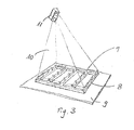
- a calibration method of a three-dimensional image acquisition system is described, which is designed as a 3D laser scanner, but it is also possible for other types of image capture. This calibration procedure does not interfere with the laser scanner itself and the calibration itself is performed during or after installation of the system or routinely occurring inaccuracies.
- the image-capturing region 10 of the laser scanner 11 is defined by the frame 8 or the balls 7 lying on it outside.
- the nominal values of the centers of the reference balls 7 are in any coordinate system, ie in a by the arrangement according to Fig. 3 predetermined coordinate system known.
- the ball diameter is known.
- a central sphere is placed approximately at the center of the image capture area, ie at the center of the scanner's coordinate system. Subsequently, the reference spheres are picked up by the scanner and a point cloud of the reference spheres is generated in the plane work area to be calibrated.
- the actual values of the ball centers are determined by dividing this point cloud into individual partial point clouds, each containing the surface points of the individual spheres (segmentation). Subsequently, the ball centers are determined from the surface points of the individual balls by means of the method of least squares.
- the scanner 11 has as an image sensor a matrix of a multiplicity of pixels, which is referred to below as a scanner matrix.
- this matrix will be determines the row and column indices associated with the detected sphere centers, denoted by z_i, s_i, where i is the number of the respective sphere.
- the coordinate system of the target values of the center points designated as target data to the coordinate system of the actual values, ie, the ball centers, which were obtained from the point cloud recorded with the scanner, called actual data, aligned.
- This alignment is done via the plane defined by the ball centers each level, ie, the level of the actual data of the ball centers is brought into alignment with the plane of the target data of the ball centers and continue to be minimized in this level, then the distances between the target and actual data of the ball centers the center at the center of the scanner's coordinate system is used for this minimization.
- the nominal and actual data were essentially the same.
- the deviations ⁇ x z_i , s_i , ⁇ y z_i , s_i , ⁇ z z_i , s_i between setpoint and actual data of the ball centers are calculated and by interpolation / extrapolation three-dimensional first correction values of all pixel elements of the scanner matrix are determined corresponding to rows and columns.
- the data of the point cloud initially recorded with the scanner is corrected with the aid of the first correction values, and the actual values of the ball centers are again determined from the corrected point cloud of the scanner, as described above. Then be again determines the row and column indices of the scanner matrix for these determined ball centers and aligns the coordinate system of the desired data to the coordinate system of the actual data, as also described above. Then, the deviations between the desired and actual data of the ball centers are determined again and determined by interpolation / extrapolation three-dimensional second correction values of all pixel elements of the scanner matrix. By summing the first and second correction values result correction matrices Ax z, s, Ay z, s, z Az, s, which are used in the following measurements for each of the three-dimensional correction of the point cloud produced by the scanner.
- the accuracy of the laser scanner used was improved by a factor of about 10 for the required object distance of more than 3 m.
Landscapes
- Engineering & Computer Science (AREA)
- Physics & Mathematics (AREA)
- General Physics & Mathematics (AREA)
- Computer Vision & Pattern Recognition (AREA)
- Mechanical Engineering (AREA)
- Automation & Control Theory (AREA)
- Optics & Photonics (AREA)
- Theoretical Computer Science (AREA)
- Plasma & Fusion (AREA)
- Length Measuring Devices By Optical Means (AREA)
- Numerical Control (AREA)
- Manipulator (AREA)
Claims (17)
- Procédé servant à commander des robots destinés à souder des pièces tridimensionnelles, comprenant les étapes suivantes consistant à :positionner et coller des profilés (3) sur une plaque (2) pour obtenir la pièce (1) à souder,disposer la plaque sur un plateau de travail,reproduire la pièce (1) au moyen d'un système d'acquisition d'images tridimensionnel sous la forme de points d'image tridimensionnels,définir les données géométriques de la plaque (2) et des profilés (3) directement à partir des points d'image tridimensionnels sous la forme de nuages de points par segmentation de ces derniers selon l'environnement et la pièce (1), la plaque (2) et les profilés (3) et les profilés (3) entre eux, en constatant des courbes des profilés et en examinant les divers profilés (3) selon leurs caractéristiques y compris selon l'association de découpes libres et de formes de rognage définitives à partir des nuages de points segmentés, sachant que la position du plan de plaque est définie et que les points de mesure de la pièce sont transformés en un système local de coordonnées de pièce dont le plan x-y coïncide avec le plan de la plaque, sachant que les points d'image du plan de plaque et les points d'image des profilés sont séparés en utilisant des coordonnées de hauteur,définir les données de soudure à partir des données géométriques en tenant compte des lignes à poser des profilés et des lignes de contact de profilés (3),associer les données de soudure aux spécifications pouvant être paramétrées pour le plan de soudage, aux modèles de déplacement préalablement définis mémorisés du robot, ainsi qu'aux instructions de commande et de réglage du processus de soudage.
- Procédé selon la revendication 1, caractérisé en ce que la représentation de la pièce (1) est appréhendée au moyen d'un scanner laser 3D (11) ou est appréhendée au moyen d'une projection de modèles et au moyen d'au moins une caméra, à l'aide d'une analyse associée.
- Procédé selon la revendication 1 ou 2, caractérisé en ce que les données géométriques sont définies par un traitement 3D.
- Procédé selon la revendication 3, caractérisé en ce que les contours de la plaque (2) sont définis pour délimiter la pièce (1) et l'environnement.
- Procédé selon la revendication 3 ou la revendication 4, caractérisé en ce que les points d'image des profilés (3) sont préalablement triés selon des structures rattachées.
- Procédé selon la revendication 5, caractérisé en ce que des courbes linéaires de profilés sont déterminées à partir des points d'image des structures rattachées.
- Procédé selon la revendication 6, caractérisé en ce que les lignes à poser des profilés et les lignes de contact de profilés (3) sont définies à partir des courbes linéaires de profilé ainsi qu'à partir de la position du plan de plaque.
- Procédé selon l'une quelconque des revendications 1 à 7, caractérisé en ce que le système d'acquisition d'images est étalonné grâce aux étapes qui suivent consistant à :a) disposer des sphères de référence dans un plan par rapport à la pièce (1) à souder ultérieurement, sachant que les valeurs théoriques des points centraux des sphères de référence relèvent d'un système de coordonnées quelconque et qu'au moins un paramètre est prédéfini pour commander la procédure d'étalonnage,b) produire un nuage de points des sphères de référence à l'aide du système d'acquisition d'images et déterminer les valeurs réelles des points centraux de sphère dans le système de coordonnées associé aux valeurs réelles,c) orienter le système de coordonnées des valeurs théoriques par rapport au système de coordonnées des valeurs réelles,d) calculer les écarts tridimensionnels entre les valeurs théoriques et les valeurs réelles des points centraux de sphère,e) déterminer des premières valeurs de correction tridimensionnelles pour des coordonnées de la zone d'acquisition d'images par interpolation/extrapolation.
- Procédé selon la revendication 8, caractérisé en ce que, à l'aide des premières valeurs de correction, le nuage de points enregistré à l'étape b) est corrigé et des valeurs réelles corrigées des points centraux de sphère sont déterminées, en ce que les étapes c) et d) sont répétées, et que des deuxièmes valeurs de correction tridimensionnelles pour les coordonnées du système d'acquisition d'images sont définies par interpolation/extrapolation, sachant que la somme des premières et deuxièmes valeurs de correction est obtenue pour définir des valeurs de correction tridimensionnelles pour le système d'acquisition d'images.
- Procédé selon la revendication 8 ou la revendication 9, sachant que le système d'acquisition d'images est un scanner laser pourvu d'une matrice de scanner en tant que capteur d'acquisition d'images, caractérisé en ce que les indices de lignes et de colonnes relevant des points centraux de sphère déterminés, de la matrice de scanner sont définis entre les étapes b) et c), et en ce que les premières valeurs de correction tridimensionnelles sont déterminées pour tous les pixels de la matrice de scanner.
- Procédé selon l'une quelconque des revendications 8 à 10, caractérisé en ce qu'également l'étape consistant à définir les indices de colonnes et de lignes, relevant des valeurs réelles à corriger des points centraux de sphère, de la matrice de scanner est répétée aux fins de la détermination des deuxièmes valeurs de correction, et en ce que des matrices de correction tridimensionnelles pour le scanner sont obtenues à partir de la somme des premières et des deuxièmes valeurs de correction.
- Procédé selon l'une quelconque des revendications 8 ou 11, caractérisé en ce que les valeurs réelles des points centraux de sphère sont définies en divisant les nuages de points en divers nuages partiels de points, en définissant les coordonnées des points de surfaces et en calculant les points centraux des diverses sphères à l'aide de la méthode des moindres carrés.
- Procédé selon l'une quelconque des revendications 8 à 10, caractérisé en ce que l'orientation est effectuée après l'étape d) par l'orientation au-dessus du plan formé par les points centraux de sphère, et en ce qu'une orientation en réduisant les écarts entre les valeurs théoriques et les valeurs réelles des points centraux de sphère ainsi que par une sphère centrale posée au centre du système de coordonnées des valeurs réelles est entreprise dans ledit plan.
- Dispositif servant à commander des robots destinées à souder des pièces tridimensionnelles, comprenant :un système d'acquisition d'images servant à appréhender une image tridimensionnelle d'une pièce (1) à souder, laquelle présente des profilés (3) collés sur une plaque (2) disposée sur un plateau de travail, et servant à fournir des données d'image sous la forme de points d'image,un module d'identification de formes géométriques, qui est réalisé pour définir les données géométriques de la plaque (2) et des profilés (3) directement à partir des points d'image tridimensionnels sous la forme de nuages de points par segmentation de ces derniers selon l'environnement et la pièce (1), la plaque (2) et les profilés (3), et les profilés (3) entre eux, en constatant des courbes de profilé et en examinant les divers profilés (3) selon leurs caractéristiques y compris l'association de coupes libres et de formes de rognage terminales à partir des nuages de points segmentés, de telle manière que la position du plan de plaque est définie et que les points de mesure de la pièce sont transformés en un système local de coordonnées de pièce, dont le plan x-y coïncide avec le plan de la plaque, sachant que le module d'identification de formes géométriques est réalisé pour séparer les points d'image du plan de plaque des points d'image des profilés en utilisant des coordonnées de hauteur, etun dispositif de commande contenant un algorithme de commande servant à associer des données de soudure à des spécifications pouvant être paramétrées pour le plan de soudage, aux modèles de déplacement mémorisés préalablement définis du robot ainsi qu'aux instructions de commande et de réglage du processus de soudage.
- Dispositif selon la revendication 14, caractérisé en ce que le système d'acquisition d'images présente un scanner laser 3D (11), qui fournit à partir de plusieurs prises de vue individuelles une modélisation 3D numérique de la pièce (1) à souder.
- Dispositif selon la revendication 14 ou 15, caractérisé en ce qu'un module d'étalonnage est prévu pour établir le lien géométrique entre les systèmes de coordonnées du robot, le système d'acquisition d'images et la pièce (1) à souder.
- Dispositif selon la revendication 16, caractérisé en ce que le module d'étalonnage contient un algorithme d'étalonnage conformément au procédé selon l'une quelconque des revendications 8 à 13.
Applications Claiming Priority (2)
| Application Number | Priority Date | Filing Date | Title |
|---|---|---|---|
| DE102007008598A DE102007008598A1 (de) | 2007-02-19 | 2007-02-19 | Automatische Programmierung von Robotern zum Abschweißen gehefteter Profile auf Mikropaneelen mit Hilfe digitaler Bilderfassung |
| PCT/EP2008/001618 WO2008101737A1 (fr) | 2007-02-19 | 2008-02-19 | Procédé et dispositif de commande de robots pour le soudage de pièces |
Publications (2)
| Publication Number | Publication Date |
|---|---|
| EP2132608A1 EP2132608A1 (fr) | 2009-12-16 |
| EP2132608B1 true EP2132608B1 (fr) | 2015-01-28 |
Family
ID=39391430
Family Applications (1)
| Application Number | Title | Priority Date | Filing Date |
|---|---|---|---|
| EP08716141.0A Active EP2132608B1 (fr) | 2007-02-19 | 2008-02-19 | Procédé et dispositif de commande de robots pour le soudage de pièces |
Country Status (7)
| Country | Link |
|---|---|
| US (1) | US8338743B2 (fr) |
| EP (1) | EP2132608B1 (fr) |
| JP (1) | JP5429872B2 (fr) |
| KR (1) | KR101051863B1 (fr) |
| CN (1) | CN101657767B (fr) |
| DE (1) | DE102007008598A1 (fr) |
| WO (1) | WO2008101737A1 (fr) |
Families Citing this family (81)
| Publication number | Priority date | Publication date | Assignee | Title |
|---|---|---|---|---|
| DE102008025647A1 (de) * | 2008-05-28 | 2009-12-17 | Lfk-Lenkflugkörpersysteme Gmbh | Heftnahtfreies Schweißen in den Nahtaußenbereichen von Bauteilen |
| US8923602B2 (en) * | 2008-07-22 | 2014-12-30 | Comau, Inc. | Automated guidance and recognition system and method of the same |
| DE102008038988B3 (de) * | 2008-08-13 | 2009-09-17 | Kraussmaffei Technologies Gmbh | Stanz- und Beschnittvorrichtung für Kunststoffbauteile |
| DE102009041734B4 (de) * | 2009-09-16 | 2023-11-02 | Kuka Roboter Gmbh | Vermessung eines Manipulators |
| EP2409808A1 (fr) | 2010-07-22 | 2012-01-25 | Bystronic Laser AG | Machine de traitement au laser |
| CN102259339A (zh) * | 2011-02-23 | 2011-11-30 | 山东华兴机械股份有限公司 | 一种机械手 |
| US10888947B2 (en) * | 2011-06-27 | 2021-01-12 | Illinois Tool Works Inc. | Workpiece-based setting of weld parameters |
| ES2875886T3 (es) * | 2011-08-03 | 2021-11-11 | D G Weld S R L | Sistema de regeneración para una matriz de forja |
| US9266182B2 (en) | 2012-04-06 | 2016-02-23 | Illinois Tools Works Inc. | Welding torch with a temperature measurement device |
| US9415459B2 (en) | 2012-04-06 | 2016-08-16 | Illinois Tool Works Inc. | Welding systems having non-contact temperature measurement systems |
| US9878393B2 (en) | 2012-06-08 | 2018-01-30 | Illinois Tool Works Inc. | Welding wire feeder power control system and method |
| US10406621B2 (en) | 2012-06-08 | 2019-09-10 | Illinois Tool Works Inc. | Polarity sensing welding wire feeder system and method |
| US10682720B2 (en) | 2012-09-07 | 2020-06-16 | Illinois Tool Works Inc. | Welding systems and devices having a configurable personal computer user interface |
| US10203683B2 (en) | 2013-07-16 | 2019-02-12 | Seagate Technology Llc | Coordinating end effector and vision controls |
| EP2883647B1 (fr) | 2013-12-12 | 2019-05-29 | Bystronic Laser AG | Procédé de configuration d'un dispositif d'usinage au laser |
| US9233469B2 (en) | 2014-02-13 | 2016-01-12 | GM Global Technology Operations LLC | Robotic system with 3D box location functionality |
| US11103948B2 (en) | 2014-08-18 | 2021-08-31 | Illinois Tool Works Inc. | Systems and methods for a personally allocated interface for use in a welding system |
| CN104384765B (zh) * | 2014-10-14 | 2016-04-27 | 江苏湃锐自动化科技有限公司 | 基于三维模型与机器视觉的自动焊接方法 |
| CN107407719B (zh) * | 2015-03-26 | 2020-12-25 | 株式会社村田制作所 | 移动体的位置检测方法 |
| WO2017009615A1 (fr) * | 2015-07-13 | 2017-01-19 | Renishaw Plc | Procédé de mesure d'un artefact |
| EP3325226B1 (fr) * | 2015-07-23 | 2022-10-26 | ABB Schweiz AG | Procédé et appareil de planification d'opérations de soudage |
| EP3325205B1 (fr) | 2015-07-23 | 2021-01-20 | ABB Schweiz AG | Procédé et appareil d'identification de cordons de soudure d'objet de soudage |
| US11491573B2 (en) | 2015-08-17 | 2022-11-08 | Illinois Tool Works Inc. | Portable advanced process module |
| EP3437083B1 (fr) * | 2016-03-28 | 2023-07-19 | ABB Schweiz AG | Procédé, système et appareil de détermination de paramètres de recherche pour un étalonnage de point de cordon de soudure |
| CN106180965A (zh) * | 2016-07-18 | 2016-12-07 | 上海发那科机器人有限公司 | 一种机器人的激光扫描焊接装置及方法 |
| CN107876953B (zh) * | 2016-09-29 | 2022-04-22 | 福特环球技术公司 | 带有位置导向系统的接合机 |
| JP6817122B2 (ja) * | 2017-03-21 | 2021-01-20 | 株式会社神戸製鋼所 | 溶接パス特定方法、プログラム、教示プログラム及び溶接ロボットシステム |
| JP6914067B2 (ja) * | 2017-03-21 | 2021-08-04 | 株式会社神戸製鋼所 | 動作プログラム補正方法および溶接ロボットシステム |
| JP6877689B2 (ja) * | 2017-03-27 | 2021-05-26 | カシオ計算機株式会社 | プログラミング装置及びその制御プログラム、プログラミング方法 |
| WO2018215592A1 (fr) * | 2017-05-24 | 2018-11-29 | Inrotech Aps | Appareil et procédé de soudage au galet automatisé d'une pièce comprenant une plaque de base présentant un motif de profils verticaux |
| CN109890690A (zh) * | 2017-09-29 | 2019-06-14 | 常石造船株式会社 | 接缝配置方法、接缝配置装置以及接缝配置程序 |
| CN111727100B (zh) * | 2018-02-26 | 2022-05-17 | 株式会社日立制作所 | 焊接动作测量系统 |
| NL2020860B1 (en) * | 2018-05-02 | 2019-11-12 | Exner Ingenieurstechniek B V | Method of, as well as a system for, performing a welding step on a work piece. |
| US11440119B2 (en) * | 2018-10-12 | 2022-09-13 | Teradyne, Inc. | System and method for weld path generation |
| CN109367693B (zh) * | 2018-10-25 | 2022-03-15 | 上海船舶工艺研究所(中国船舶工业集团公司第十一研究所) | 一种船用大型设备基座的无余量安装方法 |
| KR102125167B1 (ko) * | 2019-01-21 | 2020-06-19 | 한양대학교 에리카산학협력단 | 자동화 용접 장치 및 그의 동작 방법 |
| KR102738516B1 (ko) * | 2019-05-03 | 2024-12-06 | 현대자동차 주식회사 | 실링 로봇 티칭 시스템 및 그 방법 |
| CN110057338B (zh) * | 2019-05-24 | 2021-04-20 | 福建工程学院 | 一种基于复合测量的工件原点自适应设置方法 |
| CN110508906A (zh) * | 2019-08-30 | 2019-11-29 | 上海发那科机器人有限公司 | 一种机器人激光位移传感器寻位的方法 |
| CN110524580B (zh) * | 2019-09-16 | 2023-06-02 | 西安中科光电精密工程有限公司 | 一种焊接机器人视觉组件及其测量方法 |
| DE102020104362B4 (de) | 2020-02-19 | 2022-04-14 | Franka Emika Gmbh | Bahnplanung für einen Robotermanipulator mittels Kamerabild |
| CN111427591B (zh) * | 2020-03-19 | 2023-06-02 | Oppo(重庆)智能科技有限公司 | 程序离线制作方法、装置、存储介质及电子设备 |
| TWI764130B (zh) * | 2020-04-13 | 2022-05-11 | 迅智自動化科技股份有限公司 | 焊接系統及焊接參數優化方法 |
| CA3181027A1 (fr) * | 2020-04-14 | 2021-10-21 | Stephen PETERKIN | Ensemble soude et procede de soudage par electro-erosion |
| JP6985464B1 (ja) * | 2020-07-06 | 2021-12-22 | ジャパンマリンユナイテッド株式会社 | 溶接ロボットの動作自動生成方法及び動作自動生成システム |
| JP7303162B2 (ja) * | 2020-07-15 | 2023-07-04 | 株式会社神戸製鋼所 | 積層造形物の製造方法 |
| US11407110B2 (en) * | 2020-07-17 | 2022-08-09 | Path Robotics, Inc. | Real time feedback and dynamic adjustment for welding robots |
| CN112001935B (zh) * | 2020-07-28 | 2023-07-18 | 上海巧视智能科技有限公司 | 基于激光扫描的t型焊缝打磨方法、系统、介质及终端 |
| CN112846577A (zh) * | 2020-12-25 | 2021-05-28 | 郑智宏 | 一种提升焊接自动化的方法 |
| MX2023009878A (es) | 2021-02-24 | 2024-01-08 | Path Robotics Inc | Robots soldadores autonomos. |
| KR102452430B1 (ko) * | 2021-02-26 | 2022-10-06 | 한국로봇융합연구원 | 비전 기반 용접 대상물 인식 장치 및 방법 |
| CN113119122B (zh) * | 2021-04-10 | 2022-11-22 | 西北工业大学 | 一种机器人焊接系统的混合离线编程方法 |
| CN113399793A (zh) * | 2021-06-15 | 2021-09-17 | 广东开放大学(广东理工职业学院) | 一种薄壁钛管机器人焊接方法 |
| CN113687365B (zh) * | 2021-06-30 | 2023-12-22 | 云南昆钢电子信息科技有限公司 | 一种基于类平面多高度层轮廓识别及坐标计算方法及系统 |
| CN113533498A (zh) * | 2021-07-26 | 2021-10-22 | 成都盛锴科技有限公司 | 自动化涡流探伤系统的焊缝检测定位方法及定位装置 |
| CN113601306B (zh) * | 2021-08-04 | 2022-07-08 | 上海电器科学研究所(集团)有限公司 | 基于一维分割网络的充电设施箱体焊缝打磨方法 |
| CN113793344B (zh) * | 2021-08-31 | 2023-09-29 | 无锡砺成智能装备有限公司 | 一种基于三维点云的叶轮焊缝定位方法 |
| KR102718306B1 (ko) * | 2021-09-24 | 2024-10-17 | 가부시키가이샤 다이헨 | 용접선 검출 시스템 |
| US12157229B2 (en) * | 2021-09-24 | 2024-12-03 | Daihen Corporation | Work program production system and work program production method |
| US12277369B2 (en) | 2021-10-18 | 2025-04-15 | Path Robotics, Inc. | Generating simulated weld paths for a welding robot |
| CN113643372B (zh) * | 2021-10-18 | 2022-03-04 | 中国科学院自动化研究所 | 一种三维焊缝提取方法及系统 |
| JP7601747B2 (ja) * | 2021-11-09 | 2024-12-17 | 株式会社日立製作所 | 溶接パス自律最適化装置、溶接パス自律最適化システム、および、溶接パス自律最適化方法 |
| EP4433264A1 (fr) | 2021-11-19 | 2024-09-25 | Path Robotics, Inc. | Techniques de réglage à base de logique d'apprentissage machine pour robots |
| JP7784883B2 (ja) * | 2021-12-14 | 2025-12-12 | 株式会社ダイヘン | 溶接位置検出装置及びロボット教示システム |
| CN114055004A (zh) * | 2021-12-17 | 2022-02-18 | 宝武重工有限公司 | 一种钢结构焊接机器人智能焊接方法 |
| CN116481442B (zh) * | 2022-01-13 | 2025-08-12 | 苏州深浅优视智能科技有限公司 | 一种基于面阵结构光的翘曲板状物体厚度测量方法 |
| CN114463292B (zh) * | 2022-01-21 | 2025-08-05 | 重庆日联科技有限公司 | 一种封头焊缝x射线检测自动生成检测点位的方法 |
| CN114734439B (zh) * | 2022-04-11 | 2024-04-16 | 山东大学 | 平面对接工件焊接轨迹寻位方法和系统 |
| US12508665B2 (en) | 2022-04-19 | 2025-12-30 | Path Robotics, Inc. | Autonomous assembly robots |
| KR102424501B1 (ko) * | 2022-04-25 | 2022-07-25 | 주식회사 미주산업 | 비전인식기반 조선기자재 철의장품 로봇용접 자동화시스템 |
| US12521884B2 (en) | 2022-07-26 | 2026-01-13 | Path Robotics, Inc. | Techniques for multipass welding |
| CN115409809B (zh) * | 2022-08-31 | 2025-10-28 | 深圳前海瑞集科技有限公司 | 焊缝识别方法、装置、焊接机器人及存储介质 |
| WO2024045120A1 (fr) * | 2022-09-01 | 2024-03-07 | Squaredog Robotics Limited | Système et procédé de soudage auto-réglable |
| CN115179302B (zh) * | 2022-09-13 | 2022-12-13 | 北京石油化工学院 | 一种涉核环境下寻位-规划-纠偏的焊接机器人控制方法 |
| NL2033904B1 (en) * | 2023-01-03 | 2024-07-12 | Kranendonk Beheersmaatschappij B V | Method and system for automatically generating a weld plan for a (semi-)unique work piece. |
| CN115810133B (zh) * | 2023-02-09 | 2023-05-23 | 中建科技集团有限公司 | 基于图像处理和点云处理的焊接控制方法及相关设备 |
| CN116329738B (zh) * | 2023-03-09 | 2026-01-23 | 深圳市大族数控科技股份有限公司 | 线路板靶标的定位方法、装置、电子设备及存储介质 |
| CN116652440B (zh) * | 2023-07-31 | 2023-10-20 | 中建安装集团西安建设投资有限公司 | 钢结构数字化焊接方法及控制系统 |
| CN117798559A (zh) * | 2024-01-09 | 2024-04-02 | 武汉海伯利安软件有限公司 | 基于t型接头的焊缝自动识别方法 |
| CN117583771B (zh) * | 2024-01-19 | 2024-03-15 | 广州森弘信息科技有限公司 | 基于定向基准的焊接方法、系统及多轴焊接机器人 |
| CN118616984B (zh) * | 2024-08-05 | 2025-04-25 | 上海船舶工艺研究所(中国船舶集团有限公司第十一研究所) | 一种船舶小组立焊缝识别方法、系统、设备和存储介质 |
Family Cites Families (18)
| Publication number | Priority date | Publication date | Assignee | Title |
|---|---|---|---|---|
| US5579444A (en) * | 1987-08-28 | 1996-11-26 | Axiom Bildverarbeitungssysteme Gmbh | Adaptive vision-based controller |
| DE4115846A1 (de) * | 1991-05-15 | 1992-11-19 | Ameling Walter | Verfahren zur beruehrungslosen raeumlichen positionsmessung in roboterarbeitsraeumen |
| US6226395B1 (en) * | 1996-04-22 | 2001-05-01 | Malcolm T. Gilliland | Method and apparatus for determining the configuration of a workpiece |
| US5991437A (en) * | 1996-07-12 | 1999-11-23 | Real-Time Geometry Corporation | Modular digital audio system having individualized functional modules |
| JP3517529B2 (ja) * | 1996-08-21 | 2004-04-12 | 株式会社東芝 | 画像入力型ロボットシステム |
| DE19829661A1 (de) * | 1998-07-02 | 1999-04-22 | Georg Prof Stark | Verfahren zur rechnergestützten Erzeugung von Steuerbefehlssequenzen für Roboter |
| JP3327854B2 (ja) * | 1998-12-28 | 2002-09-24 | 川崎重工業株式会社 | 溶接ロボットの教示方法および教示装置 |
| FI117005B (fi) * | 2000-08-29 | 2006-05-15 | Aker Finnyards Oy | Hitsausjärjestely ja -menetelmä |
| DE10115149B4 (de) * | 2001-03-27 | 2004-07-29 | Vmt Bildverarbeitungssysteme Gmbh | Reintegration einer digitalen Kamera in ein Bildverarbeitungssystem, welche aus einer kalibrierten Position in eine unkalibrierte Position versetzt worden ist |
| JP4641643B2 (ja) * | 2001-03-30 | 2011-03-02 | セイコーインスツル株式会社 | 遅延回路 |
| US7143494B2 (en) * | 2001-05-16 | 2006-12-05 | Utica Enterprises, Inc. | Method and apparatus for assembling exterior automotive vehicle body components onto an automotive vehicle body |
| JP2003223213A (ja) * | 2002-01-31 | 2003-08-08 | Nippei Toyama Corp | ティーチング方法及びその装置並びにティーチング装置を備えたレーザ加工機 |
| EP1361414B1 (fr) * | 2002-05-08 | 2011-01-26 | 3D Scanners Ltd | Procédé de calibration et de qualification simultanément d'une sonde sans contact |
| SE524818C2 (sv) | 2003-02-13 | 2004-10-05 | Abb Ab | En metod och ett system för att programmera en industrirobot att förflytta sig relativt definierade positioner på ett objekt |
| JP3950805B2 (ja) * | 2003-02-27 | 2007-08-01 | ファナック株式会社 | 教示位置修正装置 |
| FI117426B (fi) * | 2003-06-12 | 2006-10-13 | Aker Yards Oy | Menetelmä kolmidimensionaalisen rakenteen hitsauksen ohjaamiseksi |
| JP4795700B2 (ja) * | 2005-02-22 | 2011-10-19 | 三菱重工業株式会社 | 曲げ加工方法、金属板、加熱位置決定プログラム、及び加熱位置決定装置 |
| US8923602B2 (en) * | 2008-07-22 | 2014-12-30 | Comau, Inc. | Automated guidance and recognition system and method of the same |
-
2007
- 2007-02-19 DE DE102007008598A patent/DE102007008598A1/de not_active Ceased
-
2008
- 2008-02-19 JP JP2009549805A patent/JP5429872B2/ja not_active Expired - Fee Related
- 2008-02-19 WO PCT/EP2008/001618 patent/WO2008101737A1/fr not_active Ceased
- 2008-02-19 KR KR1020097017929A patent/KR101051863B1/ko not_active Expired - Fee Related
- 2008-02-19 US US12/449,595 patent/US8338743B2/en not_active Expired - Fee Related
- 2008-02-19 CN CN200880005452.1A patent/CN101657767B/zh not_active Expired - Fee Related
- 2008-02-19 EP EP08716141.0A patent/EP2132608B1/fr active Active
Also Published As
| Publication number | Publication date |
|---|---|
| KR20090117757A (ko) | 2009-11-12 |
| JP2010519056A (ja) | 2010-06-03 |
| CN101657767A (zh) | 2010-02-24 |
| DE102007008598A1 (de) | 2008-08-21 |
| US20100152870A1 (en) | 2010-06-17 |
| EP2132608A1 (fr) | 2009-12-16 |
| KR101051863B1 (ko) | 2011-07-25 |
| CN101657767B (zh) | 2014-01-15 |
| WO2008101737A1 (fr) | 2008-08-28 |
| US8338743B2 (en) | 2012-12-25 |
| JP5429872B2 (ja) | 2014-02-26 |
Similar Documents
| Publication | Publication Date | Title |
|---|---|---|
| WO2008101737A1 (fr) | Procédé et dispositif de commande de robots pour le soudage de pièces | |
| EP3898060B1 (fr) | Procédé et machine à lit plat laser pour découper des pièces | |
| EP3108311B1 (fr) | Procédé, machine d'usinage et produit de programme d'ordinateur pour placer à partir d'une image des opérations d'usinage de pièces | |
| DE112010000794B4 (de) | Verfahren zum Steuern eines Roboterwerkzeuges | |
| EP3084347B1 (fr) | Procédé d'exécution et de contrôle d'une étape d'usinage sur une pièce | |
| DE102019215749B4 (de) | Bildaufnahmeeinrichtung und werkzeugmaschine | |
| DE602004005776T2 (de) | Verfahren zur Steuerung des Schweissens einer dreidimensionalen Struktur mit Aufnehmung von einem zweidimensionalen Bild der Struktur und mit Echtzeit-Justirien in der dritten Dimension | |
| DE102015012763B4 (de) | Roboterlehrvorrichtung zum Einlernen eines Roboters offline | |
| EP3221094B1 (fr) | Procédé et système de correction d'une trajectoire d'usinage d'un outil guidé par un robot | |
| DE102016119794A1 (de) | Bild-basierte technologiewahl beim laserschweissen | |
| DE102021103726A1 (de) | Messparameter-Optimierungsverfahren und -Vorrichtung sowie Computersteuerprogramm | |
| EP4121247A1 (fr) | Procédé et dispositif pour déterminer un état réel de barres de support d'un support de pièce, et machine-outil équipée d'un tel dispositif | |
| EP4037862A1 (fr) | Procédé de chargement d'un dispositif de placement de feuille d'une machine-outil à lit plat, et machine-outil à plate-forme | |
| DE102020002142B4 (de) | Verfahren zur Herstellung und Bearbeitung eines aus Stahlprofilen zusammengesetzten Rahmens | |
| DE102015214857A1 (de) | Verfahren und System zum Erstellen eines dreidimensionalen Modells einer Produktionsumgebung | |
| EP1399287B1 (fr) | Procede de coupe au rayonnement laser de pieces a assembler | |
| DE102011084353B4 (de) | Verfahren und Computerprogramm zum Einrichten eines Greifroboters, sowie Greifroboter | |
| WO2020010373A1 (fr) | Ensemble comprenant un système de traitement cnc et un dispositif d'affichage de réalité augmentée | |
| WO2025233440A1 (fr) | Dispositif de mesure optique et procédé pour mesurer optiquement des objets test | |
| EP3821305A1 (fr) | Ensemble comprenant un système de traitement cnc et un dispositif d'affichage de réalité augmentée | |
| DE102020125402A1 (de) | Schweißvorrichtung, Schweißverfahren und Computerprogrammprodukt |
Legal Events
| Date | Code | Title | Description |
|---|---|---|---|
| PUAI | Public reference made under article 153(3) epc to a published international application that has entered the european phase |
Free format text: ORIGINAL CODE: 0009012 |
|
| 17P | Request for examination filed |
Effective date: 20090918 |
|
| AK | Designated contracting states |
Kind code of ref document: A1 Designated state(s): AT BE BG CH CY CZ DE DK EE ES FI FR GB GR HR HU IE IS IT LI LT LU LV MC MT NL NO PL PT RO SE SI SK TR |
|
| 17Q | First examination report despatched |
Effective date: 20100114 |
|
| DAX | Request for extension of the european patent (deleted) | ||
| GRAP | Despatch of communication of intention to grant a patent |
Free format text: ORIGINAL CODE: EPIDOSNIGR1 |
|
| RIC1 | Information provided on ipc code assigned before grant |
Ipc: G05B 19/42 20060101AFI20140422BHEP Ipc: G01B 11/25 20060101ALI20140422BHEP Ipc: B23K 31/02 20060101ALI20140422BHEP Ipc: B23K 9/025 20060101ALI20140422BHEP Ipc: G01B 21/04 20060101ALI20140422BHEP Ipc: G06T 7/00 20060101ALI20140422BHEP |
|
| INTG | Intention to grant announced |
Effective date: 20140527 |
|
| GRAS | Grant fee paid |
Free format text: ORIGINAL CODE: EPIDOSNIGR3 |
|
| GRAP | Despatch of communication of intention to grant a patent |
Free format text: ORIGINAL CODE: EPIDOSNIGR1 |
|
| GRAA | (expected) grant |
Free format text: ORIGINAL CODE: 0009210 |
|
| INTG | Intention to grant announced |
Effective date: 20141215 |
|
| AK | Designated contracting states |
Kind code of ref document: B1 Designated state(s): AT BE BG CH CY CZ DE DK EE ES FI FR GB GR HR HU IE IS IT LI LT LU LV MC MT NL NO PL PT RO SE SI SK TR |
|
| REG | Reference to a national code |
Ref country code: GB Ref legal event code: FG4D Free format text: NOT ENGLISH |
|
| REG | Reference to a national code |
Ref country code: CH Ref legal event code: EP |
|
| REG | Reference to a national code |
Ref country code: IE Ref legal event code: FG4D Free format text: LANGUAGE OF EP DOCUMENT: GERMAN |
|
| REG | Reference to a national code |
Ref country code: DE Ref legal event code: R096 Ref document number: 502008012645 Country of ref document: DE Effective date: 20150312 |
|
| REG | Reference to a national code |
Ref country code: AT Ref legal event code: REF Ref document number: 708493 Country of ref document: AT Kind code of ref document: T Effective date: 20150315 |
|
| REG | Reference to a national code |
Ref country code: LT Ref legal event code: MG4D |
|
| REG | Reference to a national code |
Ref country code: NO Ref legal event code: T2 Effective date: 20150128 |
|
| PG25 | Lapsed in a contracting state [announced via postgrant information from national office to epo] |
Ref country code: BE Free format text: LAPSE BECAUSE OF NON-PAYMENT OF DUE FEES Effective date: 20150228 |
|
| PG25 | Lapsed in a contracting state [announced via postgrant information from national office to epo] |
Ref country code: BG Free format text: LAPSE BECAUSE OF FAILURE TO SUBMIT A TRANSLATION OF THE DESCRIPTION OR TO PAY THE FEE WITHIN THE PRESCRIBED TIME-LIMIT Effective date: 20150428 Ref country code: SE Free format text: LAPSE BECAUSE OF FAILURE TO SUBMIT A TRANSLATION OF THE DESCRIPTION OR TO PAY THE FEE WITHIN THE PRESCRIBED TIME-LIMIT Effective date: 20150128 Ref country code: HR Free format text: LAPSE BECAUSE OF FAILURE TO SUBMIT A TRANSLATION OF THE DESCRIPTION OR TO PAY THE FEE WITHIN THE PRESCRIBED TIME-LIMIT Effective date: 20150128 Ref country code: ES Free format text: LAPSE BECAUSE OF FAILURE TO SUBMIT A TRANSLATION OF THE DESCRIPTION OR TO PAY THE FEE WITHIN THE PRESCRIBED TIME-LIMIT Effective date: 20150128 Ref country code: LT Free format text: LAPSE BECAUSE OF FAILURE TO SUBMIT A TRANSLATION OF THE DESCRIPTION OR TO PAY THE FEE WITHIN THE PRESCRIBED TIME-LIMIT Effective date: 20150128 |
|
| PG25 | Lapsed in a contracting state [announced via postgrant information from national office to epo] |
Ref country code: LV Free format text: LAPSE BECAUSE OF FAILURE TO SUBMIT A TRANSLATION OF THE DESCRIPTION OR TO PAY THE FEE WITHIN THE PRESCRIBED TIME-LIMIT Effective date: 20150128 Ref country code: IS Free format text: LAPSE BECAUSE OF FAILURE TO SUBMIT A TRANSLATION OF THE DESCRIPTION OR TO PAY THE FEE WITHIN THE PRESCRIBED TIME-LIMIT Effective date: 20150528 Ref country code: PL Free format text: LAPSE BECAUSE OF FAILURE TO SUBMIT A TRANSLATION OF THE DESCRIPTION OR TO PAY THE FEE WITHIN THE PRESCRIBED TIME-LIMIT Effective date: 20150128 Ref country code: GR Free format text: LAPSE BECAUSE OF FAILURE TO SUBMIT A TRANSLATION OF THE DESCRIPTION OR TO PAY THE FEE WITHIN THE PRESCRIBED TIME-LIMIT Effective date: 20150429 |
|
| REG | Reference to a national code |
Ref country code: CH Ref legal event code: PL |
|
| REG | Reference to a national code |
Ref country code: DE Ref legal event code: R097 Ref document number: 502008012645 Country of ref document: DE |
|
| PG25 | Lapsed in a contracting state [announced via postgrant information from national office to epo] |
Ref country code: EE Free format text: LAPSE BECAUSE OF FAILURE TO SUBMIT A TRANSLATION OF THE DESCRIPTION OR TO PAY THE FEE WITHIN THE PRESCRIBED TIME-LIMIT Effective date: 20150128 Ref country code: CH Free format text: LAPSE BECAUSE OF NON-PAYMENT OF DUE FEES Effective date: 20150228 Ref country code: RO Free format text: LAPSE BECAUSE OF FAILURE TO SUBMIT A TRANSLATION OF THE DESCRIPTION OR TO PAY THE FEE WITHIN THE PRESCRIBED TIME-LIMIT Effective date: 20150128 Ref country code: LI Free format text: LAPSE BECAUSE OF NON-PAYMENT OF DUE FEES Effective date: 20150228 Ref country code: MC Free format text: LAPSE BECAUSE OF FAILURE TO SUBMIT A TRANSLATION OF THE DESCRIPTION OR TO PAY THE FEE WITHIN THE PRESCRIBED TIME-LIMIT Effective date: 20150128 Ref country code: DK Free format text: LAPSE BECAUSE OF FAILURE TO SUBMIT A TRANSLATION OF THE DESCRIPTION OR TO PAY THE FEE WITHIN THE PRESCRIBED TIME-LIMIT Effective date: 20150128 Ref country code: SK Free format text: LAPSE BECAUSE OF FAILURE TO SUBMIT A TRANSLATION OF THE DESCRIPTION OR TO PAY THE FEE WITHIN THE PRESCRIBED TIME-LIMIT Effective date: 20150128 Ref country code: CZ Free format text: LAPSE BECAUSE OF FAILURE TO SUBMIT A TRANSLATION OF THE DESCRIPTION OR TO PAY THE FEE WITHIN THE PRESCRIBED TIME-LIMIT Effective date: 20150128 |
|
| REG | Reference to a national code |
Ref country code: IE Ref legal event code: MM4A |
|
| PLBE | No opposition filed within time limit |
Free format text: ORIGINAL CODE: 0009261 |
|
| STAA | Information on the status of an ep patent application or granted ep patent |
Free format text: STATUS: NO OPPOSITION FILED WITHIN TIME LIMIT |
|
| GBPC | Gb: european patent ceased through non-payment of renewal fee |
Effective date: 20150428 |
|
| 26N | No opposition filed |
Effective date: 20151029 |
|
| REG | Reference to a national code |
Ref country code: FR Ref legal event code: ST Effective date: 20151210 |
|
| REG | Reference to a national code |
Ref country code: DE Ref legal event code: R082 Ref document number: 502008012645 Country of ref document: DE Representative=s name: PFENNING, MEINIG & PARTNER MBB PATENTANWAELTE, DE |
|
| PG25 | Lapsed in a contracting state [announced via postgrant information from national office to epo] |
Ref country code: GB Free format text: LAPSE BECAUSE OF NON-PAYMENT OF DUE FEES Effective date: 20150428 Ref country code: IE Free format text: LAPSE BECAUSE OF NON-PAYMENT OF DUE FEES Effective date: 20150219 |
|
| PG25 | Lapsed in a contracting state [announced via postgrant information from national office to epo] |
Ref country code: SI Free format text: LAPSE BECAUSE OF FAILURE TO SUBMIT A TRANSLATION OF THE DESCRIPTION OR TO PAY THE FEE WITHIN THE PRESCRIBED TIME-LIMIT Effective date: 20150128 Ref country code: FR Free format text: LAPSE BECAUSE OF NON-PAYMENT OF DUE FEES Effective date: 20150330 |
|
| REG | Reference to a national code |
Ref country code: AT Ref legal event code: MM01 Ref document number: 708493 Country of ref document: AT Kind code of ref document: T Effective date: 20150219 |
|
| PG25 | Lapsed in a contracting state [announced via postgrant information from national office to epo] |
Ref country code: AT Free format text: LAPSE BECAUSE OF NON-PAYMENT OF DUE FEES Effective date: 20150219 |
|
| PG25 | Lapsed in a contracting state [announced via postgrant information from national office to epo] |
Ref country code: MT Free format text: LAPSE BECAUSE OF FAILURE TO SUBMIT A TRANSLATION OF THE DESCRIPTION OR TO PAY THE FEE WITHIN THE PRESCRIBED TIME-LIMIT Effective date: 20150128 |
|
| PG25 | Lapsed in a contracting state [announced via postgrant information from national office to epo] |
Ref country code: HU Free format text: LAPSE BECAUSE OF FAILURE TO SUBMIT A TRANSLATION OF THE DESCRIPTION OR TO PAY THE FEE WITHIN THE PRESCRIBED TIME-LIMIT; INVALID AB INITIO Effective date: 20080219 |
|
| PG25 | Lapsed in a contracting state [announced via postgrant information from national office to epo] |
Ref country code: CY Free format text: LAPSE BECAUSE OF FAILURE TO SUBMIT A TRANSLATION OF THE DESCRIPTION OR TO PAY THE FEE WITHIN THE PRESCRIBED TIME-LIMIT Effective date: 20150128 |
|
| PG25 | Lapsed in a contracting state [announced via postgrant information from national office to epo] |
Ref country code: PT Free format text: LAPSE BECAUSE OF FAILURE TO SUBMIT A TRANSLATION OF THE DESCRIPTION OR TO PAY THE FEE WITHIN THE PRESCRIBED TIME-LIMIT Effective date: 20150528 |
|
| PG25 | Lapsed in a contracting state [announced via postgrant information from national office to epo] |
Ref country code: TR Free format text: LAPSE BECAUSE OF FAILURE TO SUBMIT A TRANSLATION OF THE DESCRIPTION OR TO PAY THE FEE WITHIN THE PRESCRIBED TIME-LIMIT Effective date: 20150128 |
|
| PG25 | Lapsed in a contracting state [announced via postgrant information from national office to epo] |
Ref country code: LU Free format text: LAPSE BECAUSE OF NON-PAYMENT OF DUE FEES Effective date: 20150219 |
|
| P01 | Opt-out of the competence of the unified patent court (upc) registered |
Effective date: 20230524 |
|
| PGFP | Annual fee paid to national office [announced via postgrant information from national office to epo] |
Ref country code: FI Payment date: 20250218 Year of fee payment: 18 |
|
| PGFP | Annual fee paid to national office [announced via postgrant information from national office to epo] |
Ref country code: NO Payment date: 20250218 Year of fee payment: 18 |
|
| PGFP | Annual fee paid to national office [announced via postgrant information from national office to epo] |
Ref country code: IT Payment date: 20250228 Year of fee payment: 18 |
|
| PGFP | Annual fee paid to national office [announced via postgrant information from national office to epo] |
Ref country code: NL Payment date: 20260218 Year of fee payment: 19 |
|
| PGFP | Annual fee paid to national office [announced via postgrant information from national office to epo] |
Ref country code: DE Payment date: 20260217 Year of fee payment: 19 |