EP3108311B1 - Procédé, machine d'usinage et produit de programme d'ordinateur pour placer à partir d'une image des opérations d'usinage de pièces - Google Patents
Procédé, machine d'usinage et produit de programme d'ordinateur pour placer à partir d'une image des opérations d'usinage de pièces Download PDFInfo
- Publication number
- EP3108311B1 EP3108311B1 EP15731016.0A EP15731016A EP3108311B1 EP 3108311 B1 EP3108311 B1 EP 3108311B1 EP 15731016 A EP15731016 A EP 15731016A EP 3108311 B1 EP3108311 B1 EP 3108311B1
- Authority
- EP
- European Patent Office
- Prior art keywords
- workpiece
- dimensional
- image
- machine
- live image
- Prior art date
- Legal status (The legal status is an assumption and is not a legal conclusion. Google has not performed a legal analysis and makes no representation as to the accuracy of the status listed.)
- Active
Links
Images


Classifications
-
- G—PHYSICS
- G05—CONTROLLING; REGULATING
- G05B—CONTROL OR REGULATING SYSTEMS IN GENERAL; FUNCTIONAL ELEMENTS OF SUCH SYSTEMS; MONITORING OR TESTING ARRANGEMENTS FOR SUCH SYSTEMS OR ELEMENTS
- G05B19/00—Program-control systems
- G05B19/02—Program-control systems electric
- G05B19/18—Numerical control [NC], i.e. automatically operating machines, in particular machine tools, e.g. in a manufacturing environment, so as to execute positioning, movement or co-ordinated operations by means of program data in numerical form
- G05B19/4097—Numerical control [NC], i.e. automatically operating machines, in particular machine tools, e.g. in a manufacturing environment, so as to execute positioning, movement or co-ordinated operations by means of program data in numerical form characterised by using design data to control NC machines, e.g. CAD/CAM
-
- B—PERFORMING OPERATIONS; TRANSPORTING
- B23—MACHINE TOOLS; METAL-WORKING NOT OTHERWISE PROVIDED FOR
- B23K—SOLDERING OR UNSOLDERING; WELDING; CLADDING OR PLATING BY SOLDERING OR WELDING; CUTTING BY APPLYING HEAT LOCALLY, e.g. FLAME CUTTING; WORKING BY LASER BEAM
- B23K26/00—Working by laser beam, e.g. welding, cutting or boring
- B23K26/02—Positioning or observing the workpiece, e.g. with respect to the point of impact; Aligning, aiming or focusing the laser beam
- B23K26/03—Observing, e.g. monitoring, the workpiece
- B23K26/032—Observing, e.g. monitoring, the workpiece using optical means
-
- B—PERFORMING OPERATIONS; TRANSPORTING
- B23—MACHINE TOOLS; METAL-WORKING NOT OTHERWISE PROVIDED FOR
- B23K—SOLDERING OR UNSOLDERING; WELDING; CLADDING OR PLATING BY SOLDERING OR WELDING; CUTTING BY APPLYING HEAT LOCALLY, e.g. FLAME CUTTING; WORKING BY LASER BEAM
- B23K26/00—Working by laser beam, e.g. welding, cutting or boring
- B23K26/08—Devices involving relative movement between laser beam and workpiece
- B23K26/0869—Devices involving movement of the laser head in at least one axial direction
- B23K26/0876—Devices involving movement of the laser head in at least one axial direction in at least two axial directions
-
- B—PERFORMING OPERATIONS; TRANSPORTING
- B23—MACHINE TOOLS; METAL-WORKING NOT OTHERWISE PROVIDED FOR
- B23K—SOLDERING OR UNSOLDERING; WELDING; CLADDING OR PLATING BY SOLDERING OR WELDING; CUTTING BY APPLYING HEAT LOCALLY, e.g. FLAME CUTTING; WORKING BY LASER BEAM
- B23K26/00—Working by laser beam, e.g. welding, cutting or boring
- B23K26/14—Working by laser beam, e.g. welding, cutting or boring using a fluid stream, e.g. a jet of gas, in conjunction with the laser beam; Nozzles therefor
-
- B—PERFORMING OPERATIONS; TRANSPORTING
- B23—MACHINE TOOLS; METAL-WORKING NOT OTHERWISE PROVIDED FOR
- B23K—SOLDERING OR UNSOLDERING; WELDING; CLADDING OR PLATING BY SOLDERING OR WELDING; CUTTING BY APPLYING HEAT LOCALLY, e.g. FLAME CUTTING; WORKING BY LASER BEAM
- B23K26/00—Working by laser beam, e.g. welding, cutting or boring
- B23K26/14—Working by laser beam, e.g. welding, cutting or boring using a fluid stream, e.g. a jet of gas, in conjunction with the laser beam; Nozzles therefor
- B23K26/1462—Nozzles; Features related to nozzles
- B23K26/1464—Supply to, or discharge from, nozzles of media, e.g. gas, powder, wire
-
- B—PERFORMING OPERATIONS; TRANSPORTING
- B23—MACHINE TOOLS; METAL-WORKING NOT OTHERWISE PROVIDED FOR
- B23K—SOLDERING OR UNSOLDERING; WELDING; CLADDING OR PLATING BY SOLDERING OR WELDING; CUTTING BY APPLYING HEAT LOCALLY, e.g. FLAME CUTTING; WORKING BY LASER BEAM
- B23K26/00—Working by laser beam, e.g. welding, cutting or boring
- B23K26/36—Removing material
- B23K26/38—Removing material by boring or cutting
-
- B—PERFORMING OPERATIONS; TRANSPORTING
- B23—MACHINE TOOLS; METAL-WORKING NOT OTHERWISE PROVIDED FOR
- B23K—SOLDERING OR UNSOLDERING; WELDING; CLADDING OR PLATING BY SOLDERING OR WELDING; CUTTING BY APPLYING HEAT LOCALLY, e.g. FLAME CUTTING; WORKING BY LASER BEAM
- B23K37/00—Auxiliary devices or processes, not specially adapted for a procedure covered by only one of the other main groups of this subclass
- B23K37/02—Carriages for supporting the welding or cutting element
- B23K37/0211—Carriages for supporting the welding or cutting element travelling on a guide member, e.g. rail, track
- B23K37/0235—Carriages for supporting the welding or cutting element travelling on a guide member, e.g. rail, track the guide member forming part of a portal
-
- B—PERFORMING OPERATIONS; TRANSPORTING
- B23—MACHINE TOOLS; METAL-WORKING NOT OTHERWISE PROVIDED FOR
- B23K—SOLDERING OR UNSOLDERING; WELDING; CLADDING OR PLATING BY SOLDERING OR WELDING; CUTTING BY APPLYING HEAT LOCALLY, e.g. FLAME CUTTING; WORKING BY LASER BEAM
- B23K37/00—Auxiliary devices or processes, not specially adapted for a procedure covered by only one of the other main groups of this subclass
- B23K37/04—Auxiliary devices or processes, not specially adapted for a procedure covered by only one of the other main groups of this subclass for holding or positioning work
- B23K37/0408—Auxiliary devices or processes, not specially adapted for a procedure covered by only one of the other main groups of this subclass for holding or positioning work for planar work
-
- G—PHYSICS
- G05—CONTROLLING; REGULATING
- G05B—CONTROL OR REGULATING SYSTEMS IN GENERAL; FUNCTIONAL ELEMENTS OF SUCH SYSTEMS; MONITORING OR TESTING ARRANGEMENTS FOR SUCH SYSTEMS OR ELEMENTS
- G05B19/00—Program-control systems
- G05B19/02—Program-control systems electric
- G05B19/18—Numerical control [NC], i.e. automatically operating machines, in particular machine tools, e.g. in a manufacturing environment, so as to execute positioning, movement or co-ordinated operations by means of program data in numerical form
- G05B19/401—Numerical control [NC], i.e. automatically operating machines, in particular machine tools, e.g. in a manufacturing environment, so as to execute positioning, movement or co-ordinated operations by means of program data in numerical form characterised by control arrangements for measuring, e.g. calibration and initialisation, measuring workpiece for machining purposes
-
- G—PHYSICS
- G05—CONTROLLING; REGULATING
- G05B—CONTROL OR REGULATING SYSTEMS IN GENERAL; FUNCTIONAL ELEMENTS OF SUCH SYSTEMS; MONITORING OR TESTING ARRANGEMENTS FOR SUCH SYSTEMS OR ELEMENTS
- G05B19/00—Program-control systems
- G05B19/02—Program-control systems electric
- G05B19/18—Numerical control [NC], i.e. automatically operating machines, in particular machine tools, e.g. in a manufacturing environment, so as to execute positioning, movement or co-ordinated operations by means of program data in numerical form
- G05B19/408—Numerical control [NC], i.e. automatically operating machines, in particular machine tools, e.g. in a manufacturing environment, so as to execute positioning, movement or co-ordinated operations by means of program data in numerical form characterised by data handling or data format, e.g. reading, buffering or conversion of data
- G05B19/4086—Coordinate conversions; Other special calculations
-
- B—PERFORMING OPERATIONS; TRANSPORTING
- B23—MACHINE TOOLS; METAL-WORKING NOT OTHERWISE PROVIDED FOR
- B23K—SOLDERING OR UNSOLDERING; WELDING; CLADDING OR PLATING BY SOLDERING OR WELDING; CUTTING BY APPLYING HEAT LOCALLY, e.g. FLAME CUTTING; WORKING BY LASER BEAM
- B23K2101/00—Articles made by soldering, welding or cutting
- B23K2101/18—Sheet panels
-
- G—PHYSICS
- G05—CONTROLLING; REGULATING
- G05B—CONTROL OR REGULATING SYSTEMS IN GENERAL; FUNCTIONAL ELEMENTS OF SUCH SYSTEMS; MONITORING OR TESTING ARRANGEMENTS FOR SUCH SYSTEMS OR ELEMENTS
- G05B2219/00—Program-control systems
- G05B2219/30—Nc systems
- G05B2219/35—Nc in input of data, input till input file format
- G05B2219/35075—Display picture of scanned object together with picture of cad object, combine
-
- G—PHYSICS
- G05—CONTROLLING; REGULATING
- G05B—CONTROL OR REGULATING SYSTEMS IN GENERAL; FUNCTIONAL ELEMENTS OF SUCH SYSTEMS; MONITORING OR TESTING ARRANGEMENTS FOR SUCH SYSTEMS OR ELEMENTS
- G05B2219/00—Program-control systems
- G05B2219/30—Nc systems
- G05B2219/35—Nc in input of data, input till input file format
- G05B2219/35162—Determine workpiece placement, nesting in blank, optimize, minimize loss material
-
- G—PHYSICS
- G05—CONTROLLING; REGULATING
- G05B—CONTROL OR REGULATING SYSTEMS IN GENERAL; FUNCTIONAL ELEMENTS OF SUCH SYSTEMS; MONITORING OR TESTING ARRANGEMENTS FOR SUCH SYSTEMS OR ELEMENTS
- G05B2219/00—Program-control systems
- G05B2219/30—Nc systems
- G05B2219/35—Nc in input of data, input till input file format
- G05B2219/35506—Camera images overlayed with graphics, model
-
- G—PHYSICS
- G05—CONTROLLING; REGULATING
- G05B—CONTROL OR REGULATING SYSTEMS IN GENERAL; FUNCTIONAL ELEMENTS OF SUCH SYSTEMS; MONITORING OR TESTING ARRANGEMENTS FOR SUCH SYSTEMS OR ELEMENTS
- G05B2219/00—Program-control systems
- G05B2219/30—Nc systems
- G05B2219/37—Measurements
- G05B2219/37009—Calibration of vision system, camera, adapt light level
-
- G—PHYSICS
- G05—CONTROLLING; REGULATING
- G05B—CONTROL OR REGULATING SYSTEMS IN GENERAL; FUNCTIONAL ELEMENTS OF SUCH SYSTEMS; MONITORING OR TESTING ARRANGEMENTS FOR SUCH SYSTEMS OR ELEMENTS
- G05B2219/00—Program-control systems
- G05B2219/30—Nc systems
- G05B2219/45—Nc applications
- G05B2219/45041—Laser cutting
-
- G—PHYSICS
- G05—CONTROLLING; REGULATING
- G05B—CONTROL OR REGULATING SYSTEMS IN GENERAL; FUNCTIONAL ELEMENTS OF SUCH SYSTEMS; MONITORING OR TESTING ARRANGEMENTS FOR SUCH SYSTEMS OR ELEMENTS
- G05B2219/00—Program-control systems
- G05B2219/30—Nc systems
- G05B2219/45—Nc applications
- G05B2219/45234—Thin flat workpiece, sheet metal machining
Definitions
- the invention relates to a method for processing flat workpieces, in particular metal sheets, or of three-dimensional workpieces on a processing machine, in particular a tool or laser cutting machine according to the preamble of claim 1, a processing machine suitable for carrying out the method and an associated computer program product.
- Such a processing method is for example by the EP 2 685 333 A2 known.
- JP 11-320143 It is known to scan a sheet to be machined using a camera two-dimensional and display together with to be cut workpiece parts on a screen and to automatically fill a free sheet metal area with other workpiece parts to be cut. However, this method presupposes that the free sheet metal area is recognized correctly by an image processing, since otherwise some, for example, soiled sheet metal areas are recognized by the image processing as already processed and therefore no longer provided for interleaving further parts.
- a method for controlling a tool in which a reference matrix of reference points and three centering points is provided in a material processing level.
- the image of the material processing level is made with the help of a camera as a camera image in the size of the camera image field.
- the camera image of the material processing plane is equalized by comparison with the reference matrix, the pixel size of the camera image is scaled by matching with the reference matrix, the camera image is centered by alignment with the centering points, and a machining contour is projected onto the rectified and scaled camera image of the workpiece.
- the machining of the workpiece is started, wherein the machining of the workpiece by the tool along the machining contour takes place.
- This object is achieved by a method for processing flat workpieces, in particular sheets, or of three-dimensional workpieces on a processing machine, in particular tool or laser cutting machine, with the features of claim 1.
- a planned workpiece machining operation to be performed (eg a laser cut to be performed) is superimposed on the live image of the workpiece as a result preview, ie displayed exactly where the workpiece machining process, eg a cutting contour, would be executed.
- a result preview ie displayed exactly where the workpiece machining process, eg a cutting contour, would be executed.
- the operator it is thus immediately apparent whether fault-free production with good material utilization is possible. If necessary, the operator can manually reposition the contour to be processed in the live image or nest it with other contours. Subsequently, the repositioned workpiece machining process is transformed back into the machine coordinate system and processed accordingly.
- the forward and backward transformations between the machine coordinate system and the live image coordinate system must be known.
- the two-dimensional live image of the image acquisition device eg a camera with a two- or three-dimensional perspective with a view of the workpiece to be processed
- the three-dimensional machine coordinate system Such a calibration can, but does not have to be done before for every new workpiece.
- a reference live image is detected with at least three machine reference points whose three-dimensional position in the machine coordinate system is known, and then the forward and backward transformations between the three-dimensional machine coordinate system and the two-dimensional live image coordinate system based on the machine reference points and their determined reference pixels in the reference live image.
- a machining contour for example, a laser cut to be performed
- reference points in the machine work space are clearly assigned to reference picture elements in the live image and thus the camera is calibrated.
- the distortion factor can be determined, for example, indirectly by taking a predetermined pattern with the camera and image analysis, or measured directly via a Shack-Hartmann arrangement and described by superposition of Zernike polynomials.
- the forward and backward transformations between the machine coordinate system and the live image coordinate system are determined much more precisely, so that less safety distance to, for example, workpiece edges or other workpiece machining needs to be maintained when manually repositioning the workpiece machining operation to be performed.
- the machine reference points in the reference live image corresponding reference pixels are manually assigned by the operator, for example by the operator selects the reference pixels in the reference live image on the user interface by clicking.
- at least some, in particular all, the machine reference points in the reference live image corresponding reference pixels are assigned by an automatic image recognition of distinctive machine reference points.
- one of the machine reference points may be formed by a traveling machine component (e.g., by the laser processing head of a laser processing machine) that has been moved to a position known in the machine coordinate system prior to acquiring the at least one reference live image.
- machine reference points can be added by machining operations in a workpiece, for example, by marking or cutting hole circles.
- contours of cut workpiece parts of a previous machining are machine reference points.
- one or more machine reference points may be generated.
- the manual repositioning comprises at least one of the following operations: turning a workpiece part to be cut, shifting a workpiece part to be cut, aligning (nesting) workpiece parts to be cut, rotating and / or displacing and / or height adjusting a lifting or pushing member (eg vacuum cleaner, magnetic, electro-adhesion or clamp gripper, or ejector pin), positioning a cut-off or teach points for other manual machining or setup operations.
- a lifting or pushing member eg vacuum cleaner, magnetic, electro-adhesion or clamp gripper, or ejector pin
- the workpiece thickness is detected before method step b) in order to not display the planned workpiece machining operation in the live image of the workpiece in the support plane (lower side) of the workpiece in method step b), but on the upper side facing the image capture device (Working plane) of the workpiece.
- workpiece machining operations can be placed in the live image instead of in the support plane in the actual working plane, which is particularly relevant for thick metal sheets.
- a CAD representation includes at least one single line superimposed in at least one defined point with a known point of the reference plane and at least one further defined point of the workpiece.
- a partial CAD representation of the workpiece on the support plane is displayed in the live image and then manually shifted (or automated by another image recognition) by an operator in the live image until it is congruent with the actual workpiece in the live image.
- the partial CAD representation can For example, only the bottom of the workpiece, or in the live image of the workpiece, the full CAD representation of the workpiece is displayed. This makes it easy to determine the positioning of the workpiece in the machine coordinate system.
- the invention also relates to a processing machine, in particular a tool or laser cutting machine, for processing flat workpieces, in particular metal sheets, or of three-dimensional workpieces having the features of claim 11.
- the invention also relates to a computer program product which has code means which are adapted to carry out all steps of the machining method according to the invention when the program runs on a machine control of a processing machine.
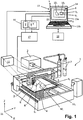
- Laser cutting machine 1 shown in perspective as a flat bed machine comprises a for example as a CO 2 laser, diode lasers or solid state laser running laser beam generator 2, a movable in X and Y direction of laser machining head 3, and a workpiece support. 4
- a laser beam 5 is generated, which by means of a (not shown) optical fiber cable or (Not shown) deflecting mirror is guided by the laser beam generator 2 to the laser processing head 3.
- the laser beam 5 is directed by means of an arranged in the laser processing head 3 focusing optics on a workpiece (eg, a sheet) 6 , which rests on the workpiece support 4.
- the laser cutting machine 1 is also supplied with process gases 7 , for example oxygen and nitrogen.
- the process gas 7 is supplied to a process gas nozzle 8 of the laser processing head 3, from which it emerges together with the laser beam 5.
- the laser cutting machine 1 is used for laser cutting workpiece parts 9 1 , 9 2 from the workpiece 6, wherein the necessary workpiece machining operations (sectional contours) with 10 1 , 10 2 are shown.
- the three-dimensional machine coordinate system XYZ is denoted overall by 11 .
- the laser processing head, or a part thereof, may function as a squeezing pin which pushes down a cut but unfolded workpiece part 9 3 for unloading at an appropriate location, as in FIG Fig. 3 is shown.
- the associated workpiece machining process, ie the pressing out of the workpiece part 9 3 by the ejector pin is designated by 10 3 .
- the laser cutting machine 1 further comprises a locally known, locally fixed image capture device 12 in the form of a camera for two-dimensional capture of an image of the workpiece support 4 and the workpiece resting thereon 6.
- the field of view of the image capture device 12 is shown with dotted lines.
- the captured image is displayed on a display 13a of a user interface 13 of the machine 1 as a live image 14 of the workpiece 6.
- the two-dimensional live image coordinate system XY of the display 13a is denoted overall by 15 .
- the laser cutting machine 1 also includes a transformation unit 16 for forward and backward transformation T , T -1 between the three-dimensional machine coordinate system 11 and the two-dimensional live image coordinate system 15, and a machine controller 17 .
- an image of the workpiece 6 to be machined is taken with the image capturing device 12 (from a 2D or 3D perspective) and displayed on the display 13a as a two-dimensional live image 14 of the workpiece 6.
- a workpiece machining operation 10 1 , 10 2 , 10 3 to be executed which is present in the three-dimensional machine coordinate system 11 as, for example, an executable machine program (NC program) is transformed in the transformation unit 16 by a predetermined forward transformation T from the three-dimensional machine coordinate system 11 into the two-dimensional live image coordinate system 15 and also in the display 13a - superimposed on the live image 14 of the workpiece 6 - displayed.
- NC program executable machine program
- the desired workpiece machining process 10 1 , 10 2 is thus displayed as a result preview in the live image 14 of the workpiece 6, so that it is immediately apparent whether a flawless production with good material utilization is possible. If necessary, the displayed workpiece machining operation 10 1, 10 2, 10 3 is now by the operator using an input device (keyboard, mouse) 13b of the user interface 13 directly in the live image 14 of the workpiece 6 are repositioned.
- an input device keyboard, mouse
- the manual repositioning can be, for example, the turning or shifting of a workpiece part 9 1 , 9 2 to be cut or its sectional contour, the alignment (nesting) of a plurality of workpiece parts 9 1 , 9 2 to be cut, or the turning and / or displacement and / or height adjustment of a lifting or pushing-out element (eg vacuum cleaner, magnetic, electro-adhesion or forceps gripper, or ejection pin), or positioning a cutting cut or teach points for other manual machining or setup operations.
- a lifting or pushing-out element eg vacuum cleaner, magnetic, electro-adhesion or forceps gripper, or ejection pin
- the workpiece machining operation 10 1 , 10 2 , 10 3 repositioned in the live image 14 in the transformation unit 16 is transformed back into the three-dimensional machine coordinate system 11 by a two-dimensional live image coordinate system 15 by a predetermined backward transformation T -1 and then on the workpiece 6 after creation of an associated NC program executed.
- the machine controller 17 is programmed to control workpiece machining according to this method.
- the workpiece thickness can be detected by measurement or manual input to the planned workpiece machining process 10 1 , 10 2 , 10 3 in the live image 14 of the workpiece. 6 not in the support plane (Bottom) of the workpiece 6, but on the image acquisition device 12 facing top (working plane) of the workpiece 6.
- workpiece machining operations 10 1 , 10 2 , 10 3 instead of placed in the support plane in the actual working plane in the live image 14, which in particular is relevant for thick sheets.
- the machine reference points P1-P4 can be arranged directly on the surface of the workpiece 6, for example by adding machine reference points P1-P4 by machining operations in a workpiece 6, for example by marking or cutting out of hole circles. It is also possible to use the contours of previously cut workpiece parts of a previous machining as machine reference points P1-P4. In addition, by projecting a point or a geometry onto one or more locations of the surface of the workpiece 6, for example with one or more (movable) laser diodes, one or more machine reference points can be generated. As a result, the (the image sensing device 12 facing) surface of the workpiece 6 forms the reference plane.
- the prerequisite for the described method for image-based repositioning of workpiece machining operations 10 1 , 10 2 , 10 3 is the determination of the forward and backward transformation T, T -1 for the calibration of the image capture device 12 with respect to the workpiece 6, around spatial points in the machine coordinate system 11 (machine workspace ) assign unique pixels in the live image coordinate system 15 or in the live image 14.
- FIG. 2 shows by way of example how the image capture device 12 can be calibrated beforehand.
- a reference image having at least three (here four) machine reference points P1-P4 whose three-dimensional position is known in the machine coordinate system 11 respectively and displayed as a reference live image 18 in the display 13a is detected.
- the forward and backward transformations T, T -1 between the three-dimensional machine coordinate system 11 and the two-dimensional live image coordinate system 15 can be determined on the basis of the machine reference points P1-P4 and their associated reference picture elements R1-R4 in the reference live picture 18.
- the machine reference points Reference pixels R1-R4 corresponding to P1-P4 in the reference live image 18 can be assigned manually or by an automatic image recognition 19 , for example, by the operator.
- the movable laser processing head 3 can also form one of the machine reference points P1-P4 if it has been moved to a position known in the machine coordinate system 11 prior to acquiring the reference live image 18.
- image capture device 12 instead of the image capture device 12 shown, multiple image capture devices 12 with overlapping or respectively adjacent viewing regions may also be used. However, it is also possible to provide one or more movable image capture devices 12, for example by arranging the image capture devices 12 on a processing unit, such as a processing unit. the laser head 3, or by a separate movable movement axis.
- a processing unit such as a processing unit. the laser head 3, or by a separate movable movement axis.
- the forward transformation T obtained from three to four machine reference points is sufficient to project two and three-dimensional representations into the two-dimensional live image 14 based on a desired reference plane (support plane).
- a desired reference plane support plane
- the forward transformation T must first be scaled accordingly.
- a CAD representation of the three-dimensional workpiece on the support plane in the live image 14 can be displayed, and the operator (or another image recognition) then moves the CAD representation until it is in the live image 14 congruent with the displayed image of the workpiece is.
- a CAD representation may include at least one single line superimposed in at least one defined point with a known point of the reference plane and at least one further defined point of the workpiece. For example, it is possible for the operator to superimpose a corner of a raised edge of a tilted workpiece 6 with a defined point of a line perpendicular to the machine coordinate system in the live image, and a point in the reference plane perpendicular to the plane Corner is to overlap with the further defined point.
- the length of the line between the two defined points determines a distance based on the known scaling factors and orientation of the line, whereby in this case the height of the upstanding corner can be determined.
- This height can be used, for example, to eject the tilted workpiece 6 with a tool from a residual grid or to ensure that there are no collision risks with the tool (eg laser head).
- This function thus represents a kind of tape measure with which dimensions can be determined in the live image to perform workpiece machining operations more accurately or more reliably.
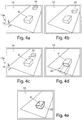
- FIG. 2 shows, by way of example, how the scaled forward and backward transformations T ', T' -1 for workpiece machining operations on a three-dimensional workpiece 6 ' can be determined from the forward and backward transformations T, T -1 known for workpiece machining operations on flat workpieces 6.
- the image of the three-dimensional workpiece 6 ', here by way of example a cuboid, taken with the image acquisition device 12 is displayed on the display 13a of the user interface 13 as a live image 14.
- a CAD representation 20 of the three-dimensional workpiece 6' is displayed by the forward transformation T of the CAD representation 20 known from the three-dimensional CAD coordinate system into the two-dimensional live image coordinate system 15 for flat workpieces 6.
- the CAD representation 20 displayed in the live image 14 is scaled differently depending on the position in which the CAD representation 20 is displayed in the live image 14.
- the displayed CAD representation 20 of the workpiece 6 ' is shifted manually by the user or automatically in the live image 14 of the workpiece 6 (FIG. FIGS. 4a-4e ) and thereby changes the underlying forward transformation.
- the size of the displayed CAD representation 20 also changes with the respective displacement position.
- the sought-forward transformations T ' for the three-dimensional workpiece 6' is found. From this, the backward transformation T ' -1 for the three-dimensional workpiece 6' can then be determined.
- the manual or automated shifting of the CAD representation 20 of the three-dimensional workpiece 6 'in the live image 14 of the workpiece 6' can take place, for example, via the operating unit 13b.
Landscapes
- Engineering & Computer Science (AREA)
- Physics & Mathematics (AREA)
- Optics & Photonics (AREA)
- Mechanical Engineering (AREA)
- Plasma & Fusion (AREA)
- Human Computer Interaction (AREA)
- Manufacturing & Machinery (AREA)
- General Physics & Mathematics (AREA)
- Automation & Control Theory (AREA)
- Numerical Control (AREA)
- Laser Beam Processing (AREA)
Claims (13)
- Procédé d'usinage de pièces plates (6), en particulier de tôles, ou de pièces tridimensionnelles (6') sur une machine d'usinage (1), en particulier une machine-outil ou une machine de découpe au laser, comprenant les étapes de procédé suivantes :a) acquisition d'une image en direct (14) d'une pièce à usiner (6 ; 6') depuis une perspective tridimensionnelle avec un dispositif d'acquisition d'image (12) permettant d'acquérir des images bidimensionnelles et d'afficher ladite image en direct acquise ;b) afficher au moins une opération d'usinage de pièce (101, 102, 103) à réaliser sous forme de prévisualisation du résultat dans l'image en direct (14) de la pièce (6 ; 6') ;c) repositionner manuellement l'opération d'usinage de pièce (101, 102, 103) à réaliser dans l'image en direct (14) de la pièce (6 ; 6') ; etd) réaliser l'opération d'usinage de pièce (101, 102, 103) sur la pièce (6 ; 6') caractérisé en ceque l'opération d'usinage de pièce (101, 102, 103) à réaliser est indiquée par une transformation directe prédéterminée (T ; T') de l'opération d'usinage de pièce (101, 102, 103) du système de coordonnées tridimensionnel de la machine (11) dans le système de coordonnées bidimensionnel de l'image en direct (15), et
que l'opération d'usinage de pièce (101, 102, 103) est réalisée par une transformation inverse prédéterminée (T-1 ; T'-1) de l'opération d'usinage de pièce (101, 102, 103) repositionnée du système de coordonnées bidimensionnel de l'image en direct (15) dans le système de coordonnées tridimensionnel de la machine (11). - Procédé selon la revendication 1, caractérisé en ce qu'avant l'étape de procédé a), une image en direct de référence (18) avec au moins trois points de référence machine (P1-P4), dont la position tridimensionnelle dans le système de coordonnées de la machine (11) est chaque fois connue, avec le dispositif d'acquisition d'image (12), et que les transformations directe et inverse (T, T-1) entre le système de coordonnées tridimensionnel de la machine (11) et le système de coordonnées bidimensionnel de l'image en direct (15) sont déterminées à l'aide des points de référence machine (P1-P4) et de leurs points d'image de référence associés (R1-R4) dans l'image en direct de référence (18).
- Procédé selon la revendication 2, caractérisé en ce qu'au moins un quatrième point de référence machine (P1-P4), dont la position tridimensionnelle dans le système de coordonnées de la machine (11) est connue, est acquis ou un facteur de distorsion, en particulier pour corriger des distorsions optiques créées par le dispositif d'acquisition d'image (12), est déterminé, et que les transformations directe et inverse (T, T-1) entre le système de coordonnées tridimensionnel de la machine (11) et le système de coordonnées bidimensionnel de l'image en direct (15) sont déterminées à l'aide desdits au moins quatre points de référence machine (P1-P4) ou à l'aide desdits au moins trois points de référence machine (P1-P4) et du facteur de distorsion, ainsi qu'à l'aide des points d'image de référence (R1-R4) associés à l'image en direct de référence (18).
- Procédé selon la revendication 2 ou 3, caractérisé en ce qu'au moins certains, en particulier tous les points d'image de référence (R1-R4) correspondant aux points de référence machine (P1-P4) dans l'image en direct de référence (18) sont associés manuellement par l'opérateur.
- Procédé selon la revendication 2 ou 3, caractérisé en ce qu'au moins certains, en particulier tous les points d'image de référence (R1-R4) correspondant aux points de référence machine (P1-P4) dans l'image en direct de référence (18) sont associés par une reconnaissance automatique d'image (19).
- Procédé selon l'une des revendications 2 à 5, caractérisé en ce qu'au moins un des points de référence machine (P1-P4) est formé par un composant mobile de la machine, en particulier une tête d'usinage au laser (3), qui est déplacé vers une position connue dans le système de coordonnées de la machine (11) avant l'acquisition de ladite au moins une image en direct de référence (18).
- Procédé selon l'une des revendications précédentes, caractérisé en ce que les transformations directe et inverse (T', T'-1) pour des opérations d'usinage de pièce sur une pièce tridimensionnelle (6') sont déterminées à partir des transformations directe et inverse (T ; T-1) connues pour des opérations d'usinage de pièce sur des pièces plates (6) comme suit :(i) affichage d'au moins une représentation CAO partielle (20) de la pièce tridimensionnelle (6') dans l'image en direct (14) de la pièce (6') par la transformation directe (T) connue pour des pièces plates (6) de la représentation CAO (20) du système de coordonnées CAO tridimensionnel dans le système de coordonnées bidimensionnel de l'image en direct (15), la représentation CAO (20) affichée dans l'image en direct (14) étant mise à l'échelle différemment en fonction de sa position dans l'image en direct (14) ; etii) adaptation des transformations directe et inverse (T ; T-1) connues pour des pièces plates (6) à la pièce tridimensionnelle (6') par déplacement de la représentation CAO (20) de la pièce tridimensionnelle (6') dépendante de la position dans l'image en direct (14) de la pièce (6) jusqu'à ce que la représentation CAO (20) soit superposée à la pièce (6') en coïncidence au moins partielle, en particulier complète, dans l'image en direct (14).
- Procédé selon la revendication 7, caractérisé en ce que la représentation CAO partielle (20) comprend au moins la face inférieure de la pièce (6').
- Procédé selon la revendication 7 ou 8, caractérisé en ce qu'une représentation CAO complète (20) de la pièce (6') est affichée dans l'image en direct (14) de la pièce (6').
- Procédé selon l'une des revendications 7 à 9, caractérisé en ce que la représentation CAO (20) dépendante de la position de la pièce (6') est déplacée manuellement dans l'image en direct (14) de la pièce (6').
- Machine d'usinage (1), en particulier machine-outil ou machine de découpe au laser, pour l'usinage de pièces plates ou tridimensionnelles (6 ; 6'), en particulier de tôles,
avec au moins un dispositif d'acquisition d'image (12) de position connue, conçu pour l'acquisition bidimensionnelle d'une image en direct (14) d'une pièce à usiner (6 ; 6') depuis une perspective tridimensionnelle,
avec une unité de transformation (16) conçue pour la transformation directe et inverse (T, T-1 ; T', T'-1) entre le système de coordonnées tridimensionnel de la machine (11) et un système de coordonnées bidimensionnelle de l'image en direct (15),
avec un affichage (13a) conçu pour afficher une image en direct (14) acquise depuis la perspective tridimensionnelle de la pièce à usiner (6 ; 6') et conçu pour afficher une opération d'usinage de pièce (101, 102, 103) à réaliser, transformée de façon directe par l'unité de transformation (16), sous forme de prévisualisation du résultat depuis la perspective tridimensionnelle dans l'image en direct (14) de la pièce (6 ; 6'),
avec une unité de commande (13b) conçue pour repositionner manuellement l'opération d'usinage de pièce (101, 102, 103) à réaliser dans l'image en direct (14) de la pièce (6 ; 6'), et
avec une commande de machine (17) programmée pour commander l'usinage de pièce conformément au procédé selon l'une des revendications précédentes. - Machine d'usinage selon la revendication 11, caractérisée par une unité de commande (13b) permettant de déplacer manuellement une représentation CAO (20) de la pièce tridimensionnelle (6') dans l'image en direct (14) de la pièce (6').
- Produit programme d'ordinateur qui présente des moyens de code adaptés à mettre en oeuvre toutes les étapes du procédé selon l'une des revendications 1 à 10 lorsque le programme est exécuté sur une commande de machine (17) d'une machine d'usinage (1).
Priority Applications (1)
| Application Number | Priority Date | Filing Date | Title |
|---|---|---|---|
| PL15731016T PL3108311T3 (pl) | 2014-07-11 | 2015-06-17 | Sposób, maszyna do obróbki i produkt w postaci programu komputerowego do bazującego na obrazie umiejscawiania procesów obróbki przedmiotów obrabianych |
Applications Claiming Priority (2)
| Application Number | Priority Date | Filing Date | Title |
|---|---|---|---|
| DE102014213518.4A DE102014213518A1 (de) | 2014-07-11 | 2014-07-11 | Verfahren, Bearbeitungsmaschine und Computerprogrammprodukt zum bildbasierten Platzieren von Werkstückbearbeitungsvorgängen |
| PCT/EP2015/063565 WO2016005159A2 (fr) | 2014-07-11 | 2015-06-17 | Procédé, machine d'usinage et produit de programme d'ordinateur pour placer à partir d'une image des processus d'usinage de pièces |
Publications (2)
| Publication Number | Publication Date |
|---|---|
| EP3108311A2 EP3108311A2 (fr) | 2016-12-28 |
| EP3108311B1 true EP3108311B1 (fr) | 2018-10-17 |
Family
ID=53483802
Family Applications (1)
| Application Number | Title | Priority Date | Filing Date |
|---|---|---|---|
| EP15731016.0A Active EP3108311B1 (fr) | 2014-07-11 | 2015-06-17 | Procédé, machine d'usinage et produit de programme d'ordinateur pour placer à partir d'une image des opérations d'usinage de pièces |
Country Status (7)
| Country | Link |
|---|---|
| US (1) | US20170115656A1 (fr) |
| EP (1) | EP3108311B1 (fr) |
| CN (1) | CN106536128B (fr) |
| DE (1) | DE102014213518A1 (fr) |
| PL (1) | PL3108311T3 (fr) |
| TR (1) | TR201820862T4 (fr) |
| WO (1) | WO2016005159A2 (fr) |
Families Citing this family (38)
| Publication number | Priority date | Publication date | Assignee | Title |
|---|---|---|---|---|
| WO2016131018A1 (fr) * | 2015-02-12 | 2016-08-18 | Glowforge Inc. | Aperçu visuel pour fabrication laser |
| EP3206099A1 (fr) * | 2016-02-12 | 2017-08-16 | ARTIS GmbH | Mmi et procédé pour commander un processus de machine-outil à commande numérique |
| CN106181029B (zh) * | 2016-08-31 | 2018-08-17 | 江苏亚威机床股份有限公司 | 一种用于激光切割区域同步伸缩皮带装置 |
| AT518890B1 (de) * | 2016-09-02 | 2018-02-15 | Trumpf Maschinen Austria Gmbh & Co Kg | Biegemaschine mit einer Arbeitsbereich-Bilderfassungsvorrichtung |
| TR201616881A2 (tr) * | 2016-11-21 | 2017-01-23 | Dener Makina Sanayi Ve Ticaret Ltd Sirketi | Levhanin eni̇ni̇n, boyunun, kesi̇m başlangiç noktasinin ve döndürme açisini tespi̇ti̇ni̇ sağlayan kamerali otomati̇k levha ölçüm si̇stemi̇ |
| IT201700091806A1 (it) * | 2017-08-08 | 2019-02-08 | Protek Srl | Metodo e relativo sistema per il taglio e/o incisione di articoli o sfridi |
| DE102017126487B4 (de) * | 2017-11-02 | 2022-05-25 | Festool Gmbh | System mit einer optischen und/oder mechanischen Referenz zur Bearbeitung eines Werkstücks |
| WO2019120481A1 (fr) * | 2017-12-19 | 2019-06-27 | Abb Schweiz Ag | Système et procédé pour déterminer une représentation de transformation |
| JP6977609B2 (ja) * | 2018-02-21 | 2021-12-08 | 株式会社リコー | 光照射装置、光照射装置を用いた光加工装置、光照射方法、及び光加工方法 |
| WO2019171150A1 (fr) * | 2018-03-08 | 2019-09-12 | Arcelormittal | Procédé de production d'une ébauche métallique soudée et ébauche métallique soudée ainsi obtenue |
| JP2019191723A (ja) * | 2018-04-20 | 2019-10-31 | 株式会社アマダホールディングス | 加工システム及び加工方法 |
| CN109702290B (zh) * | 2018-05-09 | 2020-12-22 | 中国水利水电夹江水工机械有限公司 | 基于视觉识别的钢板坡口切割方法 |
| DE102018215538A1 (de) * | 2018-09-12 | 2020-03-12 | Trumpf Werkzeugmaschinen Gmbh + Co. Kg | Verfahren und Vorrichtung zur Identifkation eines Gegenstands |
| DE102018123363B4 (de) * | 2018-09-24 | 2021-01-07 | Bystronic Laser Ag | Verfahren zur Kollisionsvermeidung und Laserbearbeitungsmaschine |
| DE102018124146A1 (de) * | 2018-09-29 | 2020-04-02 | Trumpf Werkzeugmaschinen Gmbh + Co. Kg | Schachteln von werkstücken für schneidprozesse einer flachbettwerkzeugmaschine |
| DE102018126077A1 (de) * | 2018-10-19 | 2020-04-23 | Trumpf Werkzeugmaschinen Gmbh + Co. Kg | Bewerten von werkstücklagen in geschachtelten anordnungen |
| DE102018126059A1 (de) | 2018-10-19 | 2020-04-23 | Trumpf Werkzeugmaschinen Gmbh + Co. Kg | Verfahren zum visualisieren von prozessinformationen bei der fertigung von blechbauteilen |
| DE102018126069B3 (de) | 2018-10-19 | 2019-10-02 | Trumpf Werkzeugmaschinen Gmbh + Co. Kg | Fertigungssystem und verfahren zum schachteln von teilräumen für eine ansteuerung eines schneidprozesses |
| DE102019103152A1 (de) * | 2019-02-08 | 2020-08-13 | Homag Gmbh | Bedienungsvorrichtung und Verfahren |
| CN109992125B (zh) * | 2019-03-29 | 2022-11-15 | 京东方科技集团股份有限公司 | 信息输入方法、装置和系统 |
| IT201900005174A1 (it) * | 2019-04-05 | 2020-10-05 | Automator Int S R L | Processo di marcatura laser di un oggetto e relativa apparecchiatura per la marcatura |
| WO2020210841A1 (fr) * | 2019-04-12 | 2020-10-15 | Daniel Seidel | Système de projection à zones d'exclusion interactives et réglage topologique |
| CN110376966B (zh) * | 2019-07-08 | 2022-06-10 | 长沙长泰机器人有限公司 | 一种车身主拼夹具改造方法 |
| DE102019126403B4 (de) | 2019-09-30 | 2023-03-23 | Trumpf Werkzeugmaschinen Gmbh + Co. Kg | Verfahren zum Beladen einer Tafelablagevorrichtung einer Flachbettwerkzeugmaschine und Flachbettwerkzeugmaschine |
| CN111179233B (zh) * | 2019-12-20 | 2023-05-05 | 广西柳州联耕科技有限公司 | 基于激光切割二维零部件的自适应纠偏方法 |
| DE102020204622A1 (de) * | 2020-04-09 | 2021-10-14 | Trumpf Laser Gmbh | Verfahren und Bearbeitungsmaschine zur Werkstücklageerfassung mittels OCT |
| JP7365289B2 (ja) * | 2020-04-23 | 2023-10-19 | 株式会社アマダ | スキッド状態判定装置、スキッド状態判定方法及びレーザ加工システム |
| CN111660692B (zh) * | 2020-04-28 | 2024-03-01 | 深圳大学 | 基于多波长光学褶皱识别的金融凭证智能处理系统及其装置 |
| CN112296165B (zh) * | 2020-10-10 | 2022-07-08 | 江西邦展建筑模板科技有限公司 | 一种自动定位的铝合金模板冲孔机 |
| CN114227010B (zh) * | 2021-12-31 | 2023-06-23 | 深圳市通构科技有限公司 | 通过线激光对通讯机柜外板进行切割定位的方法及装置 |
| CN114147397B (zh) * | 2022-01-11 | 2025-07-18 | 上海钛铼智钹科技有限公司 | 一种识别3d特征的自动柔性点拼焊系统 |
| CN116728110A (zh) * | 2022-03-04 | 2023-09-12 | 钱传伟 | 一种空间定位机床及加工方法 |
| DE102022110109A1 (de) | 2022-04-27 | 2023-11-02 | TRUMPF Werkzeugmaschinen SE + Co. KG | Verfahren zum Kalibrieren eines Bildverarbeitungssystems einer Blechbearbeitungsmaschine |
| DE102022110111A1 (de) | 2022-04-27 | 2023-11-02 | TRUMPF Werkzeugmaschinen SE + Co. KG | Verfahren zum Überprüfen der Kalibrierung eines Bildverarbeitungssystems einer Blechbearbeitungsmaschine |
| DE102022111316A1 (de) * | 2022-05-06 | 2023-11-09 | TRUMPF Werkzeugmaschinen SE + Co. KG | Verfahren zum Nachproduzieren von Werkstücken an einer Werkzeugmaschine sowie mobiles Endgerät dafür |
| AT526893B1 (de) * | 2023-02-09 | 2025-02-15 | Trotec Laser Gmbh | Verfahren zum Erkennen eines wechselbaren Bearbeitungstisch bzw. Tischtype eines Laserplotters zum Schneiden, Gravieren, Markieren und/oder Beschriften eines Werkstückes, sowie einen Laserplotter zum Gravieren, Markieren und/oder Beschriften eines Werkstückes hierfür |
| CN117784712B (zh) * | 2023-10-19 | 2024-10-18 | 深圳市创客工场科技有限公司 | 加工对位的实现方法、数控机器、系统和可读存储介质 |
| DE102024132188A1 (de) * | 2024-11-05 | 2026-05-07 | Fritz Studer Ag | Werkzeugmaschine, insbesondere Schleifmaschine, und Verfahren zu deren Steuerung |
Family Cites Families (24)
| Publication number | Priority date | Publication date | Assignee | Title |
|---|---|---|---|---|
| DE3627110A1 (de) * | 1986-08-06 | 1988-02-18 | Duerkopp System Technik Gmbh | Verfahren und vorrichtung zur optimierung eines materialzuschnittes |
| EP0372107B1 (fr) * | 1988-12-06 | 1994-03-02 | Dr. Johannes Heidenhain GmbH | Méthode et dispositif de simulation de l'usinage d'une pièce et sa visualisation |
| JP2690603B2 (ja) * | 1990-05-30 | 1997-12-10 | ファナック株式会社 | 視覚センサのキャリブレーション方法 |
| JP3394278B2 (ja) * | 1992-12-03 | 2003-04-07 | ファナック株式会社 | 視覚センサ座標系設定治具及び設定方法 |
| DE19522717C1 (de) * | 1995-06-22 | 1996-12-12 | Duerkopp Adler Ag | Verfahren zum Schneiden oder Stanzen einzelner Teile aus einer Tierhaut |
| JPH11320143A (ja) | 1998-05-12 | 1999-11-24 | Amada Co Ltd | 追加工装置及び方法 |
| JP4481383B2 (ja) * | 1999-04-19 | 2010-06-16 | 本田技研工業株式会社 | 形状検証システムおよび形状検証方法 |
| FI20021138A0 (fi) * | 2002-06-12 | 2002-06-12 | Kvaerner Masa Yards Oy | Menetelmä ja järjestely kappaleen/kappaleiden työstämiseksi |
| US7277599B2 (en) * | 2002-09-23 | 2007-10-02 | Regents Of The University Of Minnesota | System and method for three-dimensional video imaging using a single camera |
| US7236854B2 (en) * | 2004-01-05 | 2007-06-26 | Abb Research Ltd. | Method and a system for programming an industrial robot |
| DE102005045854B3 (de) * | 2005-09-26 | 2007-04-12 | Siemens Ag | Verfahren und System zur Kalibrierung einer Kamera in Produktionsmaschinen |
| JP5090121B2 (ja) * | 2007-10-01 | 2012-12-05 | オリンパス株式会社 | 調整装置、レーザ加工装置、調整方法、および調整プログラム |
| US9123159B2 (en) * | 2007-11-30 | 2015-09-01 | Microsoft Technology Licensing, Llc | Interactive geo-positioning of imagery |
| JP5384178B2 (ja) * | 2008-04-21 | 2014-01-08 | 株式会社森精機製作所 | 加工シミュレーション方法及び加工シミュレーション装置 |
| US8238642B2 (en) * | 2008-11-20 | 2012-08-07 | General Electric Company | Methods and apparatus for measuring 3D dimensions on 2D images |
| ES2923550T3 (es) * | 2010-10-08 | 2022-09-28 | Capsugel Belgium Nv | Aparato y procedimiento para adquirir una imagen bidimensional de la superficie de un objeto tridimensional |
| CN102609550B (zh) * | 2011-01-19 | 2015-11-25 | 鸿富锦精密工业(深圳)有限公司 | 产品三维模型自动摆正系统及方法 |
| JP5675393B2 (ja) * | 2011-01-31 | 2015-02-25 | 武蔵エンジニアリング株式会社 | 動作プログラムの自動生成プログラムおよび装置 |
| WO2012129634A2 (fr) * | 2011-03-31 | 2012-10-04 | Vision X Inc. | Détermination automatique de la conformité d'une pièce à un dessin de référence |
| DE102012106156B4 (de) * | 2012-07-09 | 2019-09-12 | Acsys Lasertechnik Gmbh | Verfahren zur Steuerung eines Werkzeuges |
| US9644942B2 (en) * | 2012-11-29 | 2017-05-09 | Mitsubishi Hitachi Power Systems, Ltd. | Method and apparatus for laser projection, and machining method |
| US9364995B2 (en) * | 2013-03-15 | 2016-06-14 | Matterrise, Inc. | Three-dimensional printing and scanning system and method |
| US20160185047A1 (en) * | 2013-08-19 | 2016-06-30 | Aio Robotics, Inc. | Four-in-one three-dimensional copy machine |
| EP2927764B1 (fr) * | 2014-04-02 | 2016-06-29 | Siemens Aktiengesellschaft | Commande numérique avec affichage de visualisation lors de changements du programme de pièces |
-
2014
- 2014-07-11 DE DE102014213518.4A patent/DE102014213518A1/de not_active Withdrawn
-
2015
- 2015-06-17 EP EP15731016.0A patent/EP3108311B1/fr active Active
- 2015-06-17 PL PL15731016T patent/PL3108311T3/pl unknown
- 2015-06-17 WO PCT/EP2015/063565 patent/WO2016005159A2/fr not_active Ceased
- 2015-06-17 CN CN201580037121.6A patent/CN106536128B/zh active Active
- 2015-06-17 TR TR2018/20862T patent/TR201820862T4/tr unknown
-
2017
- 2017-01-09 US US15/401,298 patent/US20170115656A1/en not_active Abandoned
Non-Patent Citations (1)
| Title |
|---|
| None * |
Also Published As
| Publication number | Publication date |
|---|---|
| CN106536128B (zh) | 2018-09-14 |
| EP3108311A2 (fr) | 2016-12-28 |
| DE102014213518A1 (de) | 2016-01-14 |
| TR201820862T4 (tr) | 2019-01-21 |
| PL3108311T3 (pl) | 2019-04-30 |
| CN106536128A (zh) | 2017-03-22 |
| US20170115656A1 (en) | 2017-04-27 |
| WO2016005159A2 (fr) | 2016-01-14 |
| WO2016005159A3 (fr) | 2016-06-30 |
Similar Documents
| Publication | Publication Date | Title |
|---|---|---|
| EP3108311A2 (fr) | Procédé, machine d'usinage et produit de programme d'ordinateur pour placer à partir d'une image des processus d'usinage de pièces | |
| EP3898060B1 (fr) | Procédé et machine à lit plat laser pour découper des pièces | |
| EP2132608B1 (fr) | Procédé et dispositif de commande de robots pour le soudage de pièces | |
| DE102015000587B4 (de) | Roboterprogrammiervorrichtung zum Erstellen eines Roboterprogramms zum Aufnehmen eines Bilds eines Werkstücks | |
| DE102019215749B4 (de) | Bildaufnahmeeinrichtung und werkzeugmaschine | |
| DE102017128757A1 (de) | Schleifvorrichtung | |
| EP3221094B1 (fr) | Procédé et système de correction d'une trajectoire d'usinage d'un outil guidé par un robot | |
| EP3030359B1 (fr) | Presse à plier | |
| WO2015091291A1 (fr) | Procédé d'exécution et de contrôle d'une étape d'usinage sur une pièce | |
| DE102018107857B4 (de) | Vorrichtung, System und Verfahren zur automatischen Erzeugung eines Bewegungspfads eines Roboters | |
| DE102012106156B4 (de) | Verfahren zur Steuerung eines Werkzeuges | |
| EP3403049B1 (fr) | Procédé de détermination d'une coordonnée de référence x-y-z d'une pièce et machine d'usinage | |
| DE112022000320T5 (de) | Verarbeitungsverfahren und Verarbeitungsvorrichtung zum Erzeugen eines Querschnittbildes aus durch einen visuellen Sensor erfassten Informationen über dreidimensionale Positionen | |
| DE102020002142B4 (de) | Verfahren zur Herstellung und Bearbeitung eines aus Stahlprofilen zusammengesetzten Rahmens | |
| DE102016119794A1 (de) | Bild-basierte technologiewahl beim laserschweissen | |
| DE102015104582A1 (de) | Verfahren zum Kalibrieren eines Roboters an einem Arbeitsbereich und System zum Durchführen des Verfahrens | |
| DE102020119550B4 (de) | Vorrichtung, Robotersteuereinrichtung, Robotersystem und Verfahren zum Einstellen eines Roboterkoordinatensystems | |
| EP1172183A2 (fr) | Dispositif et appareil de génération de données de déplacement corrigées pour un déplacement prédéfini d'un dispositif mobile, dispositif mobile et système composé de dispositifs mobiles | |
| DE102004020472B4 (de) | Vorrichtung und Verfahren zur Bearbeitung im wesentlicher flächiger Körper, wie Tierhäute oder Rapportstoffe oder dergleichen | |
| DE112021001048B4 (de) | Steuervorrichtung und steuerverfahren für einen roboter, robotersystem sowie vorrichtung und verfahren zum erzeugen eines betriebsprogramms eines roboters | |
| EP4076779B1 (fr) | Machine à cintrer pourvue d'un dispositif de commande | |
| DE112021007292T5 (de) | Bildgebende vorrichtung zur berechnung der dreidimensionalen lage auf der grundlage eines von einem bild-sensor aufgenommenen bildes | |
| EP2507008B1 (fr) | Dispositif de soudage avec un capteur pouvant déterminer et transmettre les coordonnées des points de la trajectoire de soudage | |
| DE102015104587A1 (de) | Verfahren zum Kalibrieren eines Roboters an einem Arbeitsbereich und System zum Durchführen des Verfahrens | |
| DE102011084353B4 (de) | Verfahren und Computerprogramm zum Einrichten eines Greifroboters, sowie Greifroboter |
Legal Events
| Date | Code | Title | Description |
|---|---|---|---|
| PUAI | Public reference made under article 153(3) epc to a published international application that has entered the european phase |
Free format text: ORIGINAL CODE: 0009012 |
|
| STAA | Information on the status of an ep patent application or granted ep patent |
Free format text: STATUS: REQUEST FOR EXAMINATION WAS MADE |
|
| 17P | Request for examination filed |
Effective date: 20160829 |
|
| AK | Designated contracting states |
Kind code of ref document: A2 Designated state(s): AL AT BE BG CH CY CZ DE DK EE ES FI FR GB GR HR HU IE IS IT LI LT LU LV MC MK MT NL NO PL PT RO RS SE SI SK SM TR |
|
| AX | Request for extension of the european patent |
Extension state: BA ME |
|
| RIN1 | Information on inventor provided before grant (corrected) |
Inventor name: OTTNAD, JENS Inventor name: KIEFER, MANUEL |
|
| STAA | Information on the status of an ep patent application or granted ep patent |
Free format text: STATUS: EXAMINATION IS IN PROGRESS |
|
| 17Q | First examination report despatched |
Effective date: 20170613 |
|
| DAV | Request for validation of the european patent (deleted) | ||
| DAX | Request for extension of the european patent (deleted) | ||
| GRAP | Despatch of communication of intention to grant a patent |
Free format text: ORIGINAL CODE: EPIDOSNIGR1 |
|
| STAA | Information on the status of an ep patent application or granted ep patent |
Free format text: STATUS: GRANT OF PATENT IS INTENDED |
|
| INTG | Intention to grant announced |
Effective date: 20180525 |
|
| GRAS | Grant fee paid |
Free format text: ORIGINAL CODE: EPIDOSNIGR3 |
|
| GRAA | (expected) grant |
Free format text: ORIGINAL CODE: 0009210 |
|
| STAA | Information on the status of an ep patent application or granted ep patent |
Free format text: STATUS: THE PATENT HAS BEEN GRANTED |
|
| AK | Designated contracting states |
Kind code of ref document: B1 Designated state(s): AL AT BE BG CH CY CZ DE DK EE ES FI FR GB GR HR HU IE IS IT LI LT LU LV MC MK MT NL NO PL PT RO RS SE SI SK SM TR |
|
| REG | Reference to a national code |
Ref country code: GB Ref legal event code: FG4D Free format text: NOT ENGLISH |
|
| REG | Reference to a national code |
Ref country code: CH Ref legal event code: EP |
|
| REG | Reference to a national code |
Ref country code: IE Ref legal event code: FG4D Free format text: LANGUAGE OF EP DOCUMENT: GERMAN |
|
| REG | Reference to a national code |
Ref country code: DE Ref legal event code: R096 Ref document number: 502015006478 Country of ref document: DE Ref country code: AT Ref legal event code: REF Ref document number: 1054742 Country of ref document: AT Kind code of ref document: T Effective date: 20181115 |
|
| REG | Reference to a national code |
Ref country code: CH Ref legal event code: NV Representative=s name: DENNEMEYER AG, CH |
|
| REG | Reference to a national code |
Ref country code: NL Ref legal event code: MP Effective date: 20181017 |
|
| REG | Reference to a national code |
Ref country code: LT Ref legal event code: MG4D |
|
| PG25 | Lapsed in a contracting state [announced via postgrant information from national office to epo] |
Ref country code: NL Free format text: LAPSE BECAUSE OF FAILURE TO SUBMIT A TRANSLATION OF THE DESCRIPTION OR TO PAY THE FEE WITHIN THE PRESCRIBED TIME-LIMIT Effective date: 20181017 |
|
| PG25 | Lapsed in a contracting state [announced via postgrant information from national office to epo] |
Ref country code: LV Free format text: LAPSE BECAUSE OF FAILURE TO SUBMIT A TRANSLATION OF THE DESCRIPTION OR TO PAY THE FEE WITHIN THE PRESCRIBED TIME-LIMIT Effective date: 20181017 Ref country code: LT Free format text: LAPSE BECAUSE OF FAILURE TO SUBMIT A TRANSLATION OF THE DESCRIPTION OR TO PAY THE FEE WITHIN THE PRESCRIBED TIME-LIMIT Effective date: 20181017 Ref country code: HR Free format text: LAPSE BECAUSE OF FAILURE TO SUBMIT A TRANSLATION OF THE DESCRIPTION OR TO PAY THE FEE WITHIN THE PRESCRIBED TIME-LIMIT Effective date: 20181017 Ref country code: BG Free format text: LAPSE BECAUSE OF FAILURE TO SUBMIT A TRANSLATION OF THE DESCRIPTION OR TO PAY THE FEE WITHIN THE PRESCRIBED TIME-LIMIT Effective date: 20190117 Ref country code: ES Free format text: LAPSE BECAUSE OF FAILURE TO SUBMIT A TRANSLATION OF THE DESCRIPTION OR TO PAY THE FEE WITHIN THE PRESCRIBED TIME-LIMIT Effective date: 20181017 Ref country code: IS Free format text: LAPSE BECAUSE OF FAILURE TO SUBMIT A TRANSLATION OF THE DESCRIPTION OR TO PAY THE FEE WITHIN THE PRESCRIBED TIME-LIMIT Effective date: 20190217 Ref country code: FI Free format text: LAPSE BECAUSE OF FAILURE TO SUBMIT A TRANSLATION OF THE DESCRIPTION OR TO PAY THE FEE WITHIN THE PRESCRIBED TIME-LIMIT Effective date: 20181017 Ref country code: NO Free format text: LAPSE BECAUSE OF FAILURE TO SUBMIT A TRANSLATION OF THE DESCRIPTION OR TO PAY THE FEE WITHIN THE PRESCRIBED TIME-LIMIT Effective date: 20190117 |
|
| PG25 | Lapsed in a contracting state [announced via postgrant information from national office to epo] |
Ref country code: RS Free format text: LAPSE BECAUSE OF FAILURE TO SUBMIT A TRANSLATION OF THE DESCRIPTION OR TO PAY THE FEE WITHIN THE PRESCRIBED TIME-LIMIT Effective date: 20181017 Ref country code: SE Free format text: LAPSE BECAUSE OF FAILURE TO SUBMIT A TRANSLATION OF THE DESCRIPTION OR TO PAY THE FEE WITHIN THE PRESCRIBED TIME-LIMIT Effective date: 20181017 Ref country code: GR Free format text: LAPSE BECAUSE OF FAILURE TO SUBMIT A TRANSLATION OF THE DESCRIPTION OR TO PAY THE FEE WITHIN THE PRESCRIBED TIME-LIMIT Effective date: 20190118 Ref country code: AL Free format text: LAPSE BECAUSE OF FAILURE TO SUBMIT A TRANSLATION OF THE DESCRIPTION OR TO PAY THE FEE WITHIN THE PRESCRIBED TIME-LIMIT Effective date: 20181017 Ref country code: PT Free format text: LAPSE BECAUSE OF FAILURE TO SUBMIT A TRANSLATION OF THE DESCRIPTION OR TO PAY THE FEE WITHIN THE PRESCRIBED TIME-LIMIT Effective date: 20190217 |
|
| REG | Reference to a national code |
Ref country code: DE Ref legal event code: R097 Ref document number: 502015006478 Country of ref document: DE |
|
| PG25 | Lapsed in a contracting state [announced via postgrant information from national office to epo] |
Ref country code: DK Free format text: LAPSE BECAUSE OF FAILURE TO SUBMIT A TRANSLATION OF THE DESCRIPTION OR TO PAY THE FEE WITHIN THE PRESCRIBED TIME-LIMIT Effective date: 20181017 Ref country code: CZ Free format text: LAPSE BECAUSE OF FAILURE TO SUBMIT A TRANSLATION OF THE DESCRIPTION OR TO PAY THE FEE WITHIN THE PRESCRIBED TIME-LIMIT Effective date: 20181017 |
|
| PLBE | No opposition filed within time limit |
Free format text: ORIGINAL CODE: 0009261 |
|
| STAA | Information on the status of an ep patent application or granted ep patent |
Free format text: STATUS: NO OPPOSITION FILED WITHIN TIME LIMIT |
|
| PG25 | Lapsed in a contracting state [announced via postgrant information from national office to epo] |
Ref country code: RO Free format text: LAPSE BECAUSE OF FAILURE TO SUBMIT A TRANSLATION OF THE DESCRIPTION OR TO PAY THE FEE WITHIN THE PRESCRIBED TIME-LIMIT Effective date: 20181017 Ref country code: SK Free format text: LAPSE BECAUSE OF FAILURE TO SUBMIT A TRANSLATION OF THE DESCRIPTION OR TO PAY THE FEE WITHIN THE PRESCRIBED TIME-LIMIT Effective date: 20181017 Ref country code: SM Free format text: LAPSE BECAUSE OF FAILURE TO SUBMIT A TRANSLATION OF THE DESCRIPTION OR TO PAY THE FEE WITHIN THE PRESCRIBED TIME-LIMIT Effective date: 20181017 Ref country code: EE Free format text: LAPSE BECAUSE OF FAILURE TO SUBMIT A TRANSLATION OF THE DESCRIPTION OR TO PAY THE FEE WITHIN THE PRESCRIBED TIME-LIMIT Effective date: 20181017 |
|
| 26N | No opposition filed |
Effective date: 20190718 |
|
| PG25 | Lapsed in a contracting state [announced via postgrant information from national office to epo] |
Ref country code: SI Free format text: LAPSE BECAUSE OF FAILURE TO SUBMIT A TRANSLATION OF THE DESCRIPTION OR TO PAY THE FEE WITHIN THE PRESCRIBED TIME-LIMIT Effective date: 20181017 |
|
| PG25 | Lapsed in a contracting state [announced via postgrant information from national office to epo] |
Ref country code: MC Free format text: LAPSE BECAUSE OF FAILURE TO SUBMIT A TRANSLATION OF THE DESCRIPTION OR TO PAY THE FEE WITHIN THE PRESCRIBED TIME-LIMIT Effective date: 20181017 |
|
| REG | Reference to a national code |
Ref country code: BE Ref legal event code: MM Effective date: 20190630 |
|
| PG25 | Lapsed in a contracting state [announced via postgrant information from national office to epo] |
Ref country code: IE Free format text: LAPSE BECAUSE OF NON-PAYMENT OF DUE FEES Effective date: 20190617 |
|
| PG25 | Lapsed in a contracting state [announced via postgrant information from national office to epo] |
Ref country code: BE Free format text: LAPSE BECAUSE OF NON-PAYMENT OF DUE FEES Effective date: 20190630 Ref country code: LU Free format text: LAPSE BECAUSE OF NON-PAYMENT OF DUE FEES Effective date: 20190617 |
|
| PG25 | Lapsed in a contracting state [announced via postgrant information from national office to epo] |
Ref country code: CY Free format text: LAPSE BECAUSE OF FAILURE TO SUBMIT A TRANSLATION OF THE DESCRIPTION OR TO PAY THE FEE WITHIN THE PRESCRIBED TIME-LIMIT Effective date: 20181017 |
|
| PG25 | Lapsed in a contracting state [announced via postgrant information from national office to epo] |
Ref country code: MT Free format text: LAPSE BECAUSE OF FAILURE TO SUBMIT A TRANSLATION OF THE DESCRIPTION OR TO PAY THE FEE WITHIN THE PRESCRIBED TIME-LIMIT Effective date: 20181017 Ref country code: HU Free format text: LAPSE BECAUSE OF FAILURE TO SUBMIT A TRANSLATION OF THE DESCRIPTION OR TO PAY THE FEE WITHIN THE PRESCRIBED TIME-LIMIT; INVALID AB INITIO Effective date: 20150617 |
|
| PGFP | Annual fee paid to national office [announced via postgrant information from national office to epo] |
Ref country code: FR Payment date: 20210622 Year of fee payment: 7 |
|
| REG | Reference to a national code |
Ref country code: AT Ref legal event code: MM01 Ref document number: 1054742 Country of ref document: AT Kind code of ref document: T Effective date: 20200617 |
|
| PGFP | Annual fee paid to national office [announced via postgrant information from national office to epo] |
Ref country code: TR Payment date: 20210614 Year of fee payment: 7 Ref country code: CH Payment date: 20210618 Year of fee payment: 7 Ref country code: GB Payment date: 20210625 Year of fee payment: 7 |
|
| PG25 | Lapsed in a contracting state [announced via postgrant information from national office to epo] |
Ref country code: AT Free format text: LAPSE BECAUSE OF NON-PAYMENT OF DUE FEES Effective date: 20200617 |
|
| PG25 | Lapsed in a contracting state [announced via postgrant information from national office to epo] |
Ref country code: MK Free format text: LAPSE BECAUSE OF FAILURE TO SUBMIT A TRANSLATION OF THE DESCRIPTION OR TO PAY THE FEE WITHIN THE PRESCRIBED TIME-LIMIT Effective date: 20181017 |
|
| REG | Reference to a national code |
Ref country code: CH Ref legal event code: PL |
|
| GBPC | Gb: european patent ceased through non-payment of renewal fee |
Effective date: 20220617 |
|
| PG25 | Lapsed in a contracting state [announced via postgrant information from national office to epo] |
Ref country code: LI Free format text: LAPSE BECAUSE OF NON-PAYMENT OF DUE FEES Effective date: 20220630 Ref country code: FR Free format text: LAPSE BECAUSE OF NON-PAYMENT OF DUE FEES Effective date: 20220630 Ref country code: CH Free format text: LAPSE BECAUSE OF NON-PAYMENT OF DUE FEES Effective date: 20220630 |
|
| PG25 | Lapsed in a contracting state [announced via postgrant information from national office to epo] |
Ref country code: GB Free format text: LAPSE BECAUSE OF NON-PAYMENT OF DUE FEES Effective date: 20220617 |
|
| PGFP | Annual fee paid to national office [announced via postgrant information from national office to epo] |
Ref country code: PL Payment date: 20250522 Year of fee payment: 11 Ref country code: DE Payment date: 20250618 Year of fee payment: 11 |
|
| PGFP | Annual fee paid to national office [announced via postgrant information from national office to epo] |
Ref country code: IT Payment date: 20250624 Year of fee payment: 11 |