EP2132973A1 - Système d'entraînement pour une machine de récolte - Google Patents
Système d'entraînement pour une machine de récolte Download PDFInfo
- Publication number
- EP2132973A1 EP2132973A1 EP09162413A EP09162413A EP2132973A1 EP 2132973 A1 EP2132973 A1 EP 2132973A1 EP 09162413 A EP09162413 A EP 09162413A EP 09162413 A EP09162413 A EP 09162413A EP 2132973 A1 EP2132973 A1 EP 2132973A1
- Authority
- EP
- European Patent Office
- Prior art keywords
- hydraulic pump
- pressure
- clutch
- displacement
- hydraulic
- Prior art date
- Legal status (The legal status is an assumption and is not a legal conclusion. Google has not performed a legal analysis and makes no representation as to the accuracy of the status listed.)
- Granted
Links
Images

Classifications
-
- F—MECHANICAL ENGINEERING; LIGHTING; HEATING; WEAPONS; BLASTING
- F16—ENGINEERING ELEMENTS AND UNITS; GENERAL MEASURES FOR PRODUCING AND MAINTAINING EFFECTIVE FUNCTIONING OF MACHINES OR INSTALLATIONS; THERMAL INSULATION IN GENERAL
- F16H—GEARING
- F16H61/00—Control functions within control units of change-speed- or reversing-gearings for conveying rotary motion ; Control of exclusively fluid gearing, friction gearing, gearings with endless flexible members or other particular types of gearing
- F16H61/38—Control of exclusively fluid gearing
- F16H61/40—Control of exclusively fluid gearing hydrostatic
- F16H61/4157—Control of braking, e.g. preventing pump over-speeding when motor acts as a pump
-
- A—HUMAN NECESSITIES
- A01—AGRICULTURE; FORESTRY; ANIMAL HUSBANDRY; HUNTING; TRAPPING; FISHING
- A01D—HARVESTING; MOWING
- A01D41/00—Combines, i.e. harvesters or mowers combined with threshing devices
- A01D41/12—Details of combines
- A01D41/127—Control or measuring arrangements specially adapted for combines
- A01D41/1274—Control or measuring arrangements specially adapted for combines for drives
-
- A—HUMAN NECESSITIES
- A01—AGRICULTURE; FORESTRY; ANIMAL HUSBANDRY; HUNTING; TRAPPING; FISHING
- A01D—HARVESTING; MOWING
- A01D69/00—Driving mechanisms or parts thereof for harvesters or mowers
- A01D69/03—Driving mechanisms or parts thereof for harvesters or mowers fluid
-
- A—HUMAN NECESSITIES
- A01—AGRICULTURE; FORESTRY; ANIMAL HUSBANDRY; HUNTING; TRAPPING; FISHING
- A01D—HARVESTING; MOWING
- A01D75/00—Accessories for harvesters or mowers
- A01D75/18—Safety devices for parts of the machines
-
- A—HUMAN NECESSITIES
- A01—AGRICULTURE; FORESTRY; ANIMAL HUSBANDRY; HUNTING; TRAPPING; FISHING
- A01F—PROCESSING OF HARVESTED PRODUCE; HAY OR STRAW PRESSES; DEVICES FOR STORING AGRICULTURAL OR HORTICULTURAL PRODUCE
- A01F29/00—Cutting apparatus specially adapted for cutting hay, straw or the like
- A01F29/09—Details
- A01F29/14—Drives
-
- A—HUMAN NECESSITIES
- A01—AGRICULTURE; FORESTRY; ANIMAL HUSBANDRY; HUNTING; TRAPPING; FISHING
- A01F—PROCESSING OF HARVESTED PRODUCE; HAY OR STRAW PRESSES; DEVICES FOR STORING AGRICULTURAL OR HORTICULTURAL PRODUCE
- A01F29/00—Cutting apparatus specially adapted for cutting hay, straw or the like
- A01F29/09—Details
- A01F29/16—Safety devices, e.g. emergency brake arrangements
-
- B—PERFORMING OPERATIONS; TRANSPORTING
- B60—VEHICLES IN GENERAL
- B60W—CONJOINT CONTROL OF VEHICLE SUB-UNITS OF DIFFERENT TYPE OR DIFFERENT FUNCTION; CONTROL SYSTEMS SPECIALLY ADAPTED FOR HYBRID VEHICLES; ROAD VEHICLE DRIVE CONTROL SYSTEMS FOR PURPOSES NOT RELATED TO THE CONTROL OF A PARTICULAR SUB-UNIT
- B60W10/00—Conjoint control of vehicle sub-units of different type or different function
- B60W10/02—Conjoint control of vehicle sub-units of different type or different function including control of driveline clutches
-
- B—PERFORMING OPERATIONS; TRANSPORTING
- B60—VEHICLES IN GENERAL
- B60W—CONJOINT CONTROL OF VEHICLE SUB-UNITS OF DIFFERENT TYPE OR DIFFERENT FUNCTION; CONTROL SYSTEMS SPECIALLY ADAPTED FOR HYBRID VEHICLES; ROAD VEHICLE DRIVE CONTROL SYSTEMS FOR PURPOSES NOT RELATED TO THE CONTROL OF A PARTICULAR SUB-UNIT
- B60W10/00—Conjoint control of vehicle sub-units of different type or different function
- B60W10/10—Conjoint control of vehicle sub-units of different type or different function including control of change-speed gearings
- B60W10/101—Infinitely variable gearings
- B60W10/103—Infinitely variable gearings of fluid type
-
- B—PERFORMING OPERATIONS; TRANSPORTING
- B60—VEHICLES IN GENERAL
- B60W—CONJOINT CONTROL OF VEHICLE SUB-UNITS OF DIFFERENT TYPE OR DIFFERENT FUNCTION; CONTROL SYSTEMS SPECIALLY ADAPTED FOR HYBRID VEHICLES; ROAD VEHICLE DRIVE CONTROL SYSTEMS FOR PURPOSES NOT RELATED TO THE CONTROL OF A PARTICULAR SUB-UNIT
- B60W10/00—Conjoint control of vehicle sub-units of different type or different function
- B60W10/30—Conjoint control of vehicle sub-units of different type or different function including control of auxiliary equipment, e.g. air-conditioning compressors or oil pumps
-
- F—MECHANICAL ENGINEERING; LIGHTING; HEATING; WEAPONS; BLASTING
- F16—ENGINEERING ELEMENTS AND UNITS; GENERAL MEASURES FOR PRODUCING AND MAINTAINING EFFECTIVE FUNCTIONING OF MACHINES OR INSTALLATIONS; THERMAL INSULATION IN GENERAL
- F16H—GEARING
- F16H61/00—Control functions within control units of change-speed- or reversing-gearings for conveying rotary motion ; Control of exclusively fluid gearing, friction gearing, gearings with endless flexible members or other particular types of gearing
- F16H61/38—Control of exclusively fluid gearing
- F16H61/40—Control of exclusively fluid gearing hydrostatic
- F16H61/42—Control of exclusively fluid gearing hydrostatic involving adjustment of a pump or motor with adjustable output or capacity
- F16H61/421—Motor capacity control by electro-hydraulic control means, e.g. using solenoid valves
-
- F—MECHANICAL ENGINEERING; LIGHTING; HEATING; WEAPONS; BLASTING
- F16—ENGINEERING ELEMENTS AND UNITS; GENERAL MEASURES FOR PRODUCING AND MAINTAINING EFFECTIVE FUNCTIONING OF MACHINES OR INSTALLATIONS; THERMAL INSULATION IN GENERAL
- F16H—GEARING
- F16H61/00—Control functions within control units of change-speed- or reversing-gearings for conveying rotary motion ; Control of exclusively fluid gearing, friction gearing, gearings with endless flexible members or other particular types of gearing
- F16H61/38—Control of exclusively fluid gearing
- F16H61/40—Control of exclusively fluid gearing hydrostatic
- F16H61/42—Control of exclusively fluid gearing hydrostatic involving adjustment of a pump or motor with adjustable output or capacity
- F16H61/431—Pump capacity control by electro-hydraulic control means, e.g. using solenoid valves
Definitions
- rotating elements pose a danger to the operator as he descends from his workplace during harvesting to clear a jam or contaminated foreign object to repair the malfunction while the element is still rotating.
- Particularly dangerous is the chopper drum of a forage harvester.
- the object underlying the invention is seen to provide a drive system for a harvester that allows stopping a Erntegutbearbeitungs sunny with little effort.
- a drive system of a harvesting machine comprises an internal combustion engine whose output shaft is connected to a crop processing device via a drive train comprising a clutch.
- the drive train is on the side of the coupling, which is connected to the Erntegutbearbeitungs announced, drive-connected or drive-connected with a hydraulic pump, which in turn is hydraulikfluid facedd with a hydraulic motor with adjustable displacement in combination.
- the hydraulic motor drives a feed conveyor of the harvester.
- a controller is connected to an actuator for opening and closing the clutch and an actuator for adjusting the displacement of the hydraulic motor.
- the internal combustion engine drives the crop processing device and the hydraulic pump via the then closed clutch and the drive train, which in turn hydraulically drives the hydraulic motor, which in turn hydraulically drives the hydraulic motor set the feed conveyor in motion.
- the operator causes the control, for example by pressing an input device or by leaving his workstation, which by a suitable monitoring device (s. EP 1 400 162 A1 ) to stop the crop processor, the controller instructs the actuator of the clutch to open the latter so that the crop processor is no longer driven by the engine.
- the controller causes the actuator of the hydraulic motor to set it to a minimum absorption volume, ie to a value of zero or almost zero.
- This pressure is reduced via a pressure limiting valve connected to the pressure connection of the hydraulic pump, via which hydraulic fluid exceeding a certain pressure can flow.
- the hydraulic pump is equipped with an adjustable displacement.
- the controller is connected to an actuator for adjusting the displacement of the hydraulic pump.
- the pressure relief valve is preferably integrated into the housing of the hydraulic pump, ie it can be used already in series existing hydraulic pumps pressure relief valve, although an external pressure relief valve can be used.
- the present invention is particularly suitable for braking a chopper of a forage harvester. But it can also be used on a combine harvester to stop a threshing cylinder or an axial crop processing device.
- FIG. 1 a harvester 10 is shown in the manner of a self-propelled forage harvester in a schematic side view.
- the harvester 10 is built on a frame 12 supported by front driven wheels 14 and steerable rear wheels 16.
- the operation of the harvesting machine 10 is carried out by a driver's cab 18, from which a header 20 in the form of a pickup is visible.
- a header 20 picked up from the ground crop, z.
- As grass or the like is fed via a feed conveyor 22 with pre-press rollers, which are arranged within a feed housing 24 on the front side of the forage harvester 10, arranged below the driver's cab 18 chopper 26 in the form of a chopper drum, which chops it into small pieces and it Releases conveyor 28.
- directional details such as laterally, downwardly and upwardly, refer to the forward direction V of the harvesting machine 10, which in FIG of the FIG. 1 goes to the right.
- FIG. 2 shows a plan view of the drive assembly of the harvester 10.
- an internal combustion engine 32 in particular in the form of a diesel engine, which is connected to longitudinal beams and / or cross members of the frame 12.
- the engine 32 extends in the forward direction of the harvester 10 to about the rear end of the frame 12 and includes a crankshaft 34 that extends forward out of the housing of the engine 32.
- the crankshaft 34 drives a horizontally and forwardly extending output shaft 36.
- the harvesting machine 10 may also have more than one internal combustion engine 32, so that the available drive power can be changed by connecting a second internal combustion engine and / or switching to a second, weaker or stronger or stronger internal combustion engine.
- the output shaft 36 is connected at its front end with an angle gear 38, which is composed of a first bevel gear 40, which is connected via a coupling 42 with the longitudinal shaft 36, and a second bevel gear 44, which meshes with the first bevel gear 40.
- the axis of rotation of the second bevel gear 44 extends horizontally and transversely to the forward direction.
- the second bevel gear 44 is connected to a shaft 46 which drives a pulley 48.
- the pulley 48 is wrapped by a drive belt 50, which also wraps around a pulley 52 for driving the conveyor 28 and a pulley 54 for driving the chopper 26.
- the angle gear 38, the shaft 46, the pulleys 48 and 54 and the drive belt 50 form a drive train connecting the output shaft 36 with the chopper 26.
- other elements of the powertrain may be arranged between the clutch 42 and the output shaft 36, such as gear transmissions, belts, and the like.
- the engine 32 could be arranged transversely to the direction of travel and the angular gear 38 omitted.
- the clutch 42 need not be designed as a friction clutch with discs, as shown, but can also be designed as a detachable and tensioned belt drive or in any other way.
- the longitudinal shaft 36 carries between the clutch 42 and the housing of the engine 32 is still a circumferentially toothed gear 56 which meshes with another gear 58, which drives a pump unit 62 via a longitudinal shaft 60, which for supplying the hydraulic motors for driving the wheels fourteenth , 16 and other hydraulically driven components of the harvester 10 is used.
- the shaft 46 is in the illustrated embodiment permanently in drive connection with a variable displacement hydraulic pump 66.
- a manual transmission between the shaft 46 and the hydraulic pump 66 is still a manual transmission arranged, which allows, instead of the hydraulic pump 66 a Coupling reversible motor to the shaft 46 to drive when the clutch 42, the chopping device 26 in relation to the harvesting operation reversed direction and to grind their knives by means of a grinding device 100.
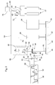
- the hydraulic pump 66 is hydraulically fluidically connected to a hydraulic motor 68, which has an adjustable displacement and via a gear 76, the pre-press rollers of the intake conveyor 22 drives.
- Another hydraulic motor 78 is used to drive the driven elements of the header 20, which could also be a corn header for maize harvesting or production of whole plant silage.
- the further hydraulic motor 78 is driven by a pump of the pump unit 62.
- An inlet 80 of the hydraulic pump 66 and an outlet 72 of the hydraulic motor 68 are connected to a container 74 for hydraulic fluid.
- a pressure port 82 of the hydraulic pump 66 and a pressure port 85 of the hydraulic motor 68 are directly through a pressure line 84, d. H. without the interposition of other valves o. ⁇ ., Interconnected.
- a pressure relief valve 86 is connected, which opens at a defined pressure at the pressure port 82 and then hydraulic fluid to the low pressure side, d. H. drains into the container 74 until the pressure is reduced and the pressure relief valve 86 closes again.
- the pressure relief valve 86 is integrated with the housing 88 of the hydraulic pump 66.
- a controller 70 (s. FIG. 1 ) is connected to an actuator 90, which operates electromagnetically or electro-hydraulically and influences the displacement of the hydraulic pump 66.
- the controller 70 is connected to an actuator 92, which operates electromagnetically or electro-hydraulically and affects the displacement of the hydraulic motor 68.
- the controller 70 is connected to an actuator 94 which opens and closes the clutch 42, and an operator input device 98 arranged in the driver's cab 18 and an operator detection device 96 likewise positioned there in the form of a camera with an image processing system based on the images of the camera can recognize whether an operator is at the workplace in the cab 18 or not. Any other operator detection means may be used, as in the EP 1 400 162 A1 is disclosed, the disclosure of which is incorporated by reference into the present documents.
- the operator input device 98 allows the operator to select a (road) driving operation in which the clutch 42 is opened and neither the chopping device 26 nor the intake conveyor 22 is driven, since the hydraulic pump 66 is stationary. Also, the header 20 is then not driven. The wheels 14 and possibly (in four-wheel drive) also 16 are driven by their hydraulic motors and the pump unit 62.
- the operator device allows the operator to select a harvesting operation in which the clutch 42 is closed and the chopper device 26 and the conveyor device 28 are driven via the drive belt 50.
- the shaft 46 then also drives the hydraulic pump 66, which acts on the hydraulic motor 68 via the pressure line 84, which in turn drives the intake conveyor 22.
- the header 20 is then driven by the pump unit 62 via the further hydraulic motor 78.
- the actuators 90, 92 are controlled by the controller 70 such that a desired cut length of the shredded material results, which can be entered by the operator input device 98 or is automatically specified by the controller on the basis of measured values of sensors that detect properties of the shredded material, such Moisture or compressibility.
- the displacement of the hydraulic motor 68 is set to the maximum possible value to achieve the desired cutting length and the displacement of the hydraulic pump 66 adjusted accordingly in order to achieve the highest possible torque of the intake conveyor 22 can.
- the adjustability of the hydraulic motor 68 makes it possible to achieve greater conveying speeds of the intake conveyor 22 and thus shorter cutting lengths compared to a hydraulic motor with fixed displacement by the actuator 92, the swash plate of the hydraulic motor 68 is brought to a position below the maximum value.
- the controller 70 may, via an appropriate input to the operator input device 98, cause the controller 70 to terminate the harvesting operation.
- the harvesting operation is also terminated automatically when the operator detection device 96 notifies the controller 70 that the operator is no longer at his workstation in the driver's cab 18.
- the controller 70 causes the actuator 94 to open the clutch 42 and the pump unit 62 to adjust the hydraulic fluid flow to the further hydraulic motor 78.
- the controller 70 causes the actuator 92 to adjust the hydraulic motor 68 to minimum displacement and the actuator 90 to provide the hydraulic pump 66 to maximum displacement.
- the Hydraulic pump 66 is further driven by the due to their moment of inertia still rotating chopper 26, the drive belt 50 and the shaft 46 and promotes against the stationary hydraulic motor 68. It builds up at the pressure port 82 of the hydraulic pump 66, therefore, a relatively high pressure, via the pressure relief valve 86 is derived.
- the rotational energy of the chopper 26 and the other with their rotating elements is converted into heat and the chopper 26 comes in a sufficiently short time to a halt, so that the operator should he, for example, want to eliminate a jam in the intake conveyor 22, not to her can hurt.
Landscapes
- Life Sciences & Earth Sciences (AREA)
- Environmental Sciences (AREA)
- Engineering & Computer Science (AREA)
- General Engineering & Computer Science (AREA)
- Mechanical Engineering (AREA)
- Harvester Elements (AREA)
- Harvesting Machines For Specific Crops (AREA)
- Fluid-Pressure Circuits (AREA)
- Auxiliary Drives, Propulsion Controls, And Safety Devices (AREA)
Applications Claiming Priority (1)
| Application Number | Priority Date | Filing Date | Title |
|---|---|---|---|
| DE102008002428A DE102008002428A1 (de) | 2008-06-13 | 2008-06-13 | Antriebssystem für eine Erntemaschine |
Publications (2)
| Publication Number | Publication Date |
|---|---|
| EP2132973A1 true EP2132973A1 (fr) | 2009-12-16 |
| EP2132973B1 EP2132973B1 (fr) | 2011-09-07 |
Family
ID=41037655
Family Applications (1)
| Application Number | Title | Priority Date | Filing Date |
|---|---|---|---|
| EP09162413A Active EP2132973B1 (fr) | 2008-06-13 | 2009-06-10 | Système d'entraînement pour une machine de récolte |
Country Status (4)
| Country | Link |
|---|---|
| EP (1) | EP2132973B1 (fr) |
| AT (1) | ATE523073T1 (fr) |
| DE (1) | DE102008002428A1 (fr) |
| EA (1) | EA016881B8 (fr) |
Cited By (2)
| Publication number | Priority date | Publication date | Assignee | Title |
|---|---|---|---|---|
| GB2479566A (en) * | 2010-04-15 | 2011-10-19 | Agco Int Gmbh | Braking system for a rotating chopper drum of a forage harvester |
| DE102018205221A1 (de) | 2018-04-06 | 2019-10-10 | Deere & Company | Feldhäcksler mit schnittlängenabhängiger Drehzahl der Konditioniereinrichtung |
Families Citing this family (8)
| Publication number | Priority date | Publication date | Assignee | Title |
|---|---|---|---|---|
| DE102011014245A1 (de) | 2011-03-17 | 2012-09-20 | Claas Saulgau Gmbh | Verfahren und Vorrichtung zum Betreiben eines Feldhäckslers |
| DE102012107227B4 (de) | 2012-08-07 | 2022-07-14 | Linde Hydraulics Gmbh & Co. Kg | Antriebssystem zum Antrieb einer Häcksel- und Einzugsvorrichtung einer Erntemaschine |
| DE102014219205B4 (de) | 2014-09-23 | 2024-08-01 | Deere & Company | Antriebssystem für eine Erntemaschine |
| DE102019213353A1 (de) | 2019-09-03 | 2021-03-04 | Deere & Company | Antriebssystem für eine Erntemaschine |
| DE102022126007A1 (de) | 2022-10-07 | 2024-04-18 | Deere & Company | Antriebssystem für eine Erntemaschine |
| DE102023102472A1 (de) | 2023-02-01 | 2024-08-01 | Deere & Company | Antriebsanordnung für eine Erntemaschine |
| DE102023135106A1 (de) | 2023-12-14 | 2025-06-18 | Deere & Company | Antriebssystem für einen Feldhäcksler |
| DE102024130767A1 (de) | 2024-10-22 | 2026-04-23 | Deere & Company | Steueranordnung zur Kontrolle einer an der Unterseite eines stromab einer Häckseltrommel angeordneten Kanals eines Feldhäckslers angeordneten Verschlusseinrichtung |
Citations (6)
| Publication number | Priority date | Publication date | Assignee | Title |
|---|---|---|---|---|
| US3736753A (en) * | 1971-09-22 | 1973-06-05 | Deere & Co | Hydraulic drive |
| WO2002009498A1 (fr) * | 2000-07-27 | 2002-02-07 | Case Harvesting Systems Gmbh | Ramasseuse-hacheuse comportant des organes de ramassage entraines hydrauliquement |
| EP1400162A1 (fr) | 2002-09-19 | 2004-03-24 | Deere & Company | Dispositif de sécurité pour une machine de récolte |
| EP1554920A1 (fr) * | 2004-01-14 | 2005-07-20 | CNH Belgium N.V. | Transmission à double source de puissance pour un tambour d'une récolteuse et méthode pour la décélération du tambour |
| EP1721518A1 (fr) | 2005-05-13 | 2006-11-15 | CLAAS Selbstfahrende Erntemaschinen GmbH | Régulation d'un organe d'alimentation d'une machine de travail agricole |
| DE102008002344A1 (de) | 2008-06-11 | 2009-12-17 | Deere & Company, Moline | Antriebssystem für eine Erntemaschine |
Family Cites Families (2)
| Publication number | Priority date | Publication date | Assignee | Title |
|---|---|---|---|---|
| SU1630922A1 (ru) * | 1988-05-11 | 1991-02-28 | Подмосковный филиал Государственного союзного научно-исследовательского тракторного института | Гидростатическа трансмисси комбайна |
| DE10260480A1 (de) * | 2002-12-21 | 2004-07-01 | Deere & Company, Moline | Antriebssystem einer selbstfahrenden Arbeitsmaschine |
-
2008
- 2008-06-13 DE DE102008002428A patent/DE102008002428A1/de not_active Withdrawn
-
2009
- 2009-05-28 EA EA200900619A patent/EA016881B8/ru not_active IP Right Cessation
- 2009-06-10 EP EP09162413A patent/EP2132973B1/fr active Active
- 2009-06-10 AT AT09162413T patent/ATE523073T1/de active
Patent Citations (6)
| Publication number | Priority date | Publication date | Assignee | Title |
|---|---|---|---|---|
| US3736753A (en) * | 1971-09-22 | 1973-06-05 | Deere & Co | Hydraulic drive |
| WO2002009498A1 (fr) * | 2000-07-27 | 2002-02-07 | Case Harvesting Systems Gmbh | Ramasseuse-hacheuse comportant des organes de ramassage entraines hydrauliquement |
| EP1400162A1 (fr) | 2002-09-19 | 2004-03-24 | Deere & Company | Dispositif de sécurité pour une machine de récolte |
| EP1554920A1 (fr) * | 2004-01-14 | 2005-07-20 | CNH Belgium N.V. | Transmission à double source de puissance pour un tambour d'une récolteuse et méthode pour la décélération du tambour |
| EP1721518A1 (fr) | 2005-05-13 | 2006-11-15 | CLAAS Selbstfahrende Erntemaschinen GmbH | Régulation d'un organe d'alimentation d'une machine de travail agricole |
| DE102008002344A1 (de) | 2008-06-11 | 2009-12-17 | Deere & Company, Moline | Antriebssystem für eine Erntemaschine |
Non-Patent Citations (1)
| Title |
|---|
| H. SCHNEIDER; T. RHODY: "Differenzflächenventile (Logikelemente) für Schnellstop und Messertrommel-Bremse an einem Feldhäcksler", VDI-BERICHTE, 2005, pages 237 - 242 |
Cited By (4)
| Publication number | Priority date | Publication date | Assignee | Title |
|---|---|---|---|---|
| GB2479566A (en) * | 2010-04-15 | 2011-10-19 | Agco Int Gmbh | Braking system for a rotating chopper drum of a forage harvester |
| EP2557911B1 (fr) * | 2010-04-15 | 2016-03-16 | AGCO International GmbH | Récolteuses-hacheuses |
| DE102018205221A1 (de) | 2018-04-06 | 2019-10-10 | Deere & Company | Feldhäcksler mit schnittlängenabhängiger Drehzahl der Konditioniereinrichtung |
| BE1026188A1 (de) | 2018-04-06 | 2019-10-30 | Deere & Co | Feldhäcksler mit schnittlängenabhängiger Drehzahl der Konditioniereinrichtung |
Also Published As
| Publication number | Publication date |
|---|---|
| ATE523073T1 (de) | 2011-09-15 |
| EA200900619A8 (ru) | 2012-07-30 |
| EA200900619A1 (ru) | 2009-12-30 |
| EP2132973B1 (fr) | 2011-09-07 |
| EA016881B1 (ru) | 2012-08-30 |
| DE102008002428A1 (de) | 2009-12-17 |
| EA016881B8 (ru) | 2012-10-30 |
Similar Documents
| Publication | Publication Date | Title |
|---|---|---|
| EP2132973B1 (fr) | Système d'entraînement pour une machine de récolte | |
| EP2312928B1 (fr) | Système d'entraînement pour un transporteur d'alimentation de moissonneuse | |
| BE1023763B1 (de) | Antriebssystem für eine erntemaschine | |
| BE1023764B1 (de) | Feldhäcksler mit reversierbarer konditioniereinrichtung | |
| EP2952087B1 (fr) | Système d'entraînement d'une moissonneuse automotrice | |
| EP2860397B1 (fr) | Système d'entraînement pour organes de travail entraînés hydrauliquement d'une machine de travail | |
| BE1022206B1 (de) | Antriebssystem fur einen einzugsforderer oder erntevorsatz einer erntemaschine mit richtungsabhangigem maximalmoment. | |
| BE1026188B1 (de) | Feldhäcksler mit schnittlängenabhängiger Drehzahl der Konditioniereinrichtung | |
| BE1021620B1 (de) | Antriebssystem für eine erntemaschine | |
| EP3326446B1 (fr) | Dispositif de commande de vitesse d'une moissonneuse | |
| BE1027492B1 (de) | Antriebssystem für eine Erntemaschine | |
| BE1024973A1 (de) | Antriebsanordnung zum drehzahlveränderbaren Antrieb einer mit zwei Konditionierwalzen ausgestatteten Konditioniereinrichtung eines Feldhäckslers | |
| DE102009028094B4 (de) | Selbstfahrende Erntemaschine | |
| DE102017214097A1 (de) | Antriebssystem für einen Erntevorsatz einer Erntemaschine mit selbsttätiger Abschaltung bei Überlast | |
| EP3348135B1 (fr) | Système d'entraînement pour une tête de récolte d'une machine de récolte à arrêt automatique lors de surcharge | |
| EP2132975B1 (fr) | Système d'entraînement pour une moissonneuse | |
| DE102012107227B4 (de) | Antriebssystem zum Antrieb einer Häcksel- und Einzugsvorrichtung einer Erntemaschine | |
| BE1030888B1 (de) | Antriebssystem für eine Erntemaschine | |
| BE1022416B1 (de) | Selbstfahrende arbeitsmaschine mit hydrostatischem fahrantrieb | |
| BE1027694B1 (de) | Antriebsanordnung für ein landwirtschaftliches Arbeitsgerät mit mechanischer Überlastkupplung und selbsttätiger Anpassung des Abschaltmoments | |
| DE102009028055B4 (de) | Selbstfahrende Erntemaschine | |
| DE102024130767A1 (de) | Steueranordnung zur Kontrolle einer an der Unterseite eines stromab einer Häckseltrommel angeordneten Kanals eines Feldhäckslers angeordneten Verschlusseinrichtung | |
| EP3639649B1 (fr) | Système pour entraînement à changement de vitesse de rotation d'un agencement de conditionnement équipé de deux rouleaux de conditionnement d'une ramasseuse-hacheuse |
Legal Events
| Date | Code | Title | Description |
|---|---|---|---|
| PUAI | Public reference made under article 153(3) epc to a published international application that has entered the european phase |
Free format text: ORIGINAL CODE: 0009012 |
|
| AK | Designated contracting states |
Kind code of ref document: A1 Designated state(s): AT BE BG CH CY CZ DE DK EE ES FI FR GB GR HR HU IE IS IT LI LT LU LV MC MK MT NL NO PL PT RO SE SI SK TR |
|
| 17P | Request for examination filed |
Effective date: 20100616 |
|
| 17Q | First examination report despatched |
Effective date: 20100712 |
|
| GRAP | Despatch of communication of intention to grant a patent |
Free format text: ORIGINAL CODE: EPIDOSNIGR1 |
|
| GRAS | Grant fee paid |
Free format text: ORIGINAL CODE: EPIDOSNIGR3 |
|
| GRAA | (expected) grant |
Free format text: ORIGINAL CODE: 0009210 |
|
| REG | Reference to a national code |
Ref country code: GB Ref legal event code: FG4D Free format text: NOT ENGLISH |
|
| REG | Reference to a national code |
Ref country code: CH Ref legal event code: EP |
|
| REG | Reference to a national code |
Ref country code: IE Ref legal event code: FG4D Free format text: LANGUAGE OF EP DOCUMENT: GERMAN |
|
| REG | Reference to a national code |
Ref country code: DE Ref legal event code: R096 Ref document number: 502009001300 Country of ref document: DE Effective date: 20111103 |
|
| REG | Reference to a national code |
Ref country code: NL Ref legal event code: VDEP Effective date: 20110907 |
|
| PG25 | Lapsed in a contracting state [announced via postgrant information from national office to epo] |
Ref country code: NO Free format text: LAPSE BECAUSE OF FAILURE TO SUBMIT A TRANSLATION OF THE DESCRIPTION OR TO PAY THE FEE WITHIN THE PRESCRIBED TIME-LIMIT Effective date: 20111207 Ref country code: SE Free format text: LAPSE BECAUSE OF FAILURE TO SUBMIT A TRANSLATION OF THE DESCRIPTION OR TO PAY THE FEE WITHIN THE PRESCRIBED TIME-LIMIT Effective date: 20110907 Ref country code: HR Free format text: LAPSE BECAUSE OF FAILURE TO SUBMIT A TRANSLATION OF THE DESCRIPTION OR TO PAY THE FEE WITHIN THE PRESCRIBED TIME-LIMIT Effective date: 20110907 Ref country code: FI Free format text: LAPSE BECAUSE OF FAILURE TO SUBMIT A TRANSLATION OF THE DESCRIPTION OR TO PAY THE FEE WITHIN THE PRESCRIBED TIME-LIMIT Effective date: 20110907 Ref country code: LT Free format text: LAPSE BECAUSE OF FAILURE TO SUBMIT A TRANSLATION OF THE DESCRIPTION OR TO PAY THE FEE WITHIN THE PRESCRIBED TIME-LIMIT Effective date: 20110907 |
|
| LTIE | Lt: invalidation of european patent or patent extension |
Effective date: 20110907 |
|
| PG25 | Lapsed in a contracting state [announced via postgrant information from national office to epo] |
Ref country code: SI Free format text: LAPSE BECAUSE OF FAILURE TO SUBMIT A TRANSLATION OF THE DESCRIPTION OR TO PAY THE FEE WITHIN THE PRESCRIBED TIME-LIMIT Effective date: 20110907 Ref country code: LV Free format text: LAPSE BECAUSE OF FAILURE TO SUBMIT A TRANSLATION OF THE DESCRIPTION OR TO PAY THE FEE WITHIN THE PRESCRIBED TIME-LIMIT Effective date: 20110907 Ref country code: GR Free format text: LAPSE BECAUSE OF FAILURE TO SUBMIT A TRANSLATION OF THE DESCRIPTION OR TO PAY THE FEE WITHIN THE PRESCRIBED TIME-LIMIT Effective date: 20111208 Ref country code: CY Free format text: LAPSE BECAUSE OF FAILURE TO SUBMIT A TRANSLATION OF THE DESCRIPTION OR TO PAY THE FEE WITHIN THE PRESCRIBED TIME-LIMIT Effective date: 20110907 |
|
| REG | Reference to a national code |
Ref country code: IE Ref legal event code: FD4D |
|
| PG25 | Lapsed in a contracting state [announced via postgrant information from national office to epo] |
Ref country code: SK Free format text: LAPSE BECAUSE OF FAILURE TO SUBMIT A TRANSLATION OF THE DESCRIPTION OR TO PAY THE FEE WITHIN THE PRESCRIBED TIME-LIMIT Effective date: 20110907 Ref country code: IS Free format text: LAPSE BECAUSE OF FAILURE TO SUBMIT A TRANSLATION OF THE DESCRIPTION OR TO PAY THE FEE WITHIN THE PRESCRIBED TIME-LIMIT Effective date: 20120107 Ref country code: CZ Free format text: LAPSE BECAUSE OF FAILURE TO SUBMIT A TRANSLATION OF THE DESCRIPTION OR TO PAY THE FEE WITHIN THE PRESCRIBED TIME-LIMIT Effective date: 20110907 Ref country code: IE Free format text: LAPSE BECAUSE OF FAILURE TO SUBMIT A TRANSLATION OF THE DESCRIPTION OR TO PAY THE FEE WITHIN THE PRESCRIBED TIME-LIMIT Effective date: 20110907 |
|
| PG25 | Lapsed in a contracting state [announced via postgrant information from national office to epo] |
Ref country code: PL Free format text: LAPSE BECAUSE OF FAILURE TO SUBMIT A TRANSLATION OF THE DESCRIPTION OR TO PAY THE FEE WITHIN THE PRESCRIBED TIME-LIMIT Effective date: 20110907 Ref country code: RO Free format text: LAPSE BECAUSE OF FAILURE TO SUBMIT A TRANSLATION OF THE DESCRIPTION OR TO PAY THE FEE WITHIN THE PRESCRIBED TIME-LIMIT Effective date: 20110907 Ref country code: IT Free format text: LAPSE BECAUSE OF FAILURE TO SUBMIT A TRANSLATION OF THE DESCRIPTION OR TO PAY THE FEE WITHIN THE PRESCRIBED TIME-LIMIT Effective date: 20110907 Ref country code: NL Free format text: LAPSE BECAUSE OF FAILURE TO SUBMIT A TRANSLATION OF THE DESCRIPTION OR TO PAY THE FEE WITHIN THE PRESCRIBED TIME-LIMIT Effective date: 20110907 Ref country code: EE Free format text: LAPSE BECAUSE OF FAILURE TO SUBMIT A TRANSLATION OF THE DESCRIPTION OR TO PAY THE FEE WITHIN THE PRESCRIBED TIME-LIMIT Effective date: 20110907 Ref country code: PT Free format text: LAPSE BECAUSE OF FAILURE TO SUBMIT A TRANSLATION OF THE DESCRIPTION OR TO PAY THE FEE WITHIN THE PRESCRIBED TIME-LIMIT Effective date: 20120109 |
|
| PLBE | No opposition filed within time limit |
Free format text: ORIGINAL CODE: 0009261 |
|
| STAA | Information on the status of an ep patent application or granted ep patent |
Free format text: STATUS: NO OPPOSITION FILED WITHIN TIME LIMIT |
|
| PG25 | Lapsed in a contracting state [announced via postgrant information from national office to epo] |
Ref country code: DK Free format text: LAPSE BECAUSE OF FAILURE TO SUBMIT A TRANSLATION OF THE DESCRIPTION OR TO PAY THE FEE WITHIN THE PRESCRIBED TIME-LIMIT Effective date: 20110907 |
|
| 26N | No opposition filed |
Effective date: 20120611 |
|
| REG | Reference to a national code |
Ref country code: DE Ref legal event code: R097 Ref document number: 502009001300 Country of ref document: DE Effective date: 20120611 |
|
| PG25 | Lapsed in a contracting state [announced via postgrant information from national office to epo] |
Ref country code: MC Free format text: LAPSE BECAUSE OF NON-PAYMENT OF DUE FEES Effective date: 20120630 |
|
| PG25 | Lapsed in a contracting state [announced via postgrant information from national office to epo] |
Ref country code: MK Free format text: LAPSE BECAUSE OF FAILURE TO SUBMIT A TRANSLATION OF THE DESCRIPTION OR TO PAY THE FEE WITHIN THE PRESCRIBED TIME-LIMIT Effective date: 20110907 |
|
| REG | Reference to a national code |
Ref country code: FR Ref legal event code: ST Effective date: 20130228 |
|
| PG25 | Lapsed in a contracting state [announced via postgrant information from national office to epo] |
Ref country code: ES Free format text: LAPSE BECAUSE OF FAILURE TO SUBMIT A TRANSLATION OF THE DESCRIPTION OR TO PAY THE FEE WITHIN THE PRESCRIBED TIME-LIMIT Effective date: 20111218 Ref country code: FR Free format text: LAPSE BECAUSE OF NON-PAYMENT OF DUE FEES Effective date: 20120702 |
|
| PG25 | Lapsed in a contracting state [announced via postgrant information from national office to epo] |
Ref country code: BG Free format text: LAPSE BECAUSE OF FAILURE TO SUBMIT A TRANSLATION OF THE DESCRIPTION OR TO PAY THE FEE WITHIN THE PRESCRIBED TIME-LIMIT Effective date: 20111207 |
|
| PG25 | Lapsed in a contracting state [announced via postgrant information from national office to epo] |
Ref country code: MT Free format text: LAPSE BECAUSE OF FAILURE TO SUBMIT A TRANSLATION OF THE DESCRIPTION OR TO PAY THE FEE WITHIN THE PRESCRIBED TIME-LIMIT Effective date: 20110907 |
|
| REG | Reference to a national code |
Ref country code: CH Ref legal event code: PL |
|
| GBPC | Gb: european patent ceased through non-payment of renewal fee |
Effective date: 20130610 |
|
| PG25 | Lapsed in a contracting state [announced via postgrant information from national office to epo] |
Ref country code: LI Free format text: LAPSE BECAUSE OF NON-PAYMENT OF DUE FEES Effective date: 20130630 Ref country code: CH Free format text: LAPSE BECAUSE OF NON-PAYMENT OF DUE FEES Effective date: 20130630 Ref country code: GB Free format text: LAPSE BECAUSE OF NON-PAYMENT OF DUE FEES Effective date: 20130610 Ref country code: TR Free format text: LAPSE BECAUSE OF FAILURE TO SUBMIT A TRANSLATION OF THE DESCRIPTION OR TO PAY THE FEE WITHIN THE PRESCRIBED TIME-LIMIT Effective date: 20110907 |
|
| PG25 | Lapsed in a contracting state [announced via postgrant information from national office to epo] |
Ref country code: LU Free format text: LAPSE BECAUSE OF NON-PAYMENT OF DUE FEES Effective date: 20120610 |
|
| PG25 | Lapsed in a contracting state [announced via postgrant information from national office to epo] |
Ref country code: HU Free format text: LAPSE BECAUSE OF FAILURE TO SUBMIT A TRANSLATION OF THE DESCRIPTION OR TO PAY THE FEE WITHIN THE PRESCRIBED TIME-LIMIT Effective date: 20090610 |
|
| REG | Reference to a national code |
Ref country code: AT Ref legal event code: MM01 Ref document number: 523073 Country of ref document: AT Kind code of ref document: T Effective date: 20140610 |
|
| PG25 | Lapsed in a contracting state [announced via postgrant information from national office to epo] |
Ref country code: AT Free format text: LAPSE BECAUSE OF NON-PAYMENT OF DUE FEES Effective date: 20140610 |
|
| PGFP | Annual fee paid to national office [announced via postgrant information from national office to epo] |
Ref country code: DE Payment date: 20250521 Year of fee payment: 17 |
|
| PGFP | Annual fee paid to national office [announced via postgrant information from national office to epo] |
Ref country code: BE Payment date: 20250627 Year of fee payment: 17 |
|
| REG | Reference to a national code |
Ref country code: DE Ref legal event code: R084 Ref document number: 502009001300 Country of ref document: DE |