EP2133192A2 - Vorrichtung zur Gasexposition - Google Patents
Vorrichtung zur Gasexposition Download PDFInfo
- Publication number
- EP2133192A2 EP2133192A2 EP09158342A EP09158342A EP2133192A2 EP 2133192 A2 EP2133192 A2 EP 2133192A2 EP 09158342 A EP09158342 A EP 09158342A EP 09158342 A EP09158342 A EP 09158342A EP 2133192 A2 EP2133192 A2 EP 2133192A2
- Authority
- EP
- European Patent Office
- Prior art keywords
- gas
- reaction space
- siphon
- liquid
- strand
- Prior art date
- Legal status (The legal status is an assumption and is not a legal conclusion. Google has not performed a legal analysis and makes no representation as to the accuracy of the status listed.)
- Granted
Links
- 238000006243 chemical reaction Methods 0.000 claims abstract description 124
- 239000000203 mixture Substances 0.000 claims abstract description 41
- 229920001971 elastomer Polymers 0.000 claims abstract description 31
- 239000000806 elastomer Substances 0.000 claims abstract description 29
- 230000026030 halogenation Effects 0.000 claims abstract description 16
- 238000005658 halogenation reaction Methods 0.000 claims abstract description 16
- 238000000034 method Methods 0.000 claims abstract description 8
- XLYOFNOQVPJJNP-UHFFFAOYSA-N water Substances O XLYOFNOQVPJJNP-UHFFFAOYSA-N 0.000 claims abstract description 5
- 239000007789 gas Substances 0.000 claims description 194
- 239000007788 liquid Substances 0.000 claims description 77
- 229910052736 halogen Inorganic materials 0.000 claims description 40
- 150000002367 halogens Chemical class 0.000 claims description 40
- 238000001704 evaporation Methods 0.000 claims description 10
- ZAMOUSCENKQFHK-UHFFFAOYSA-N Chlorine atom Chemical compound [Cl] ZAMOUSCENKQFHK-UHFFFAOYSA-N 0.000 claims description 7
- 239000000460 chlorine Substances 0.000 claims description 7
- 229910052801 chlorine Inorganic materials 0.000 claims description 7
- IJGRMHOSHXDMSA-UHFFFAOYSA-N Atomic nitrogen Chemical compound N#N IJGRMHOSHXDMSA-UHFFFAOYSA-N 0.000 claims description 6
- WKBOTKDWSSQWDR-UHFFFAOYSA-N Bromine atom Chemical compound [Br] WKBOTKDWSSQWDR-UHFFFAOYSA-N 0.000 claims description 4
- PXGOKWXKJXAPGV-UHFFFAOYSA-N Fluorine Chemical compound FF PXGOKWXKJXAPGV-UHFFFAOYSA-N 0.000 claims description 4
- GDTBXPJZTBHREO-UHFFFAOYSA-N bromine Substances BrBr GDTBXPJZTBHREO-UHFFFAOYSA-N 0.000 claims description 4
- 229910052794 bromium Inorganic materials 0.000 claims description 4
- 229910052731 fluorine Inorganic materials 0.000 claims description 4
- 239000011737 fluorine Substances 0.000 claims description 4
- 229910052757 nitrogen Inorganic materials 0.000 claims description 3
- 239000012530 fluid Substances 0.000 abstract description 6
- 238000001035 drying Methods 0.000 description 9
- 230000008020 evaporation Effects 0.000 description 6
- 238000000746 purification Methods 0.000 description 5
- 229920002943 EPDM rubber Polymers 0.000 description 3
- 244000043261 Hevea brasiliensis Species 0.000 description 3
- 230000007423 decrease Effects 0.000 description 3
- 229920003052 natural elastomer Polymers 0.000 description 3
- 229920001194 natural rubber Polymers 0.000 description 3
- 229920000459 Nitrile rubber Polymers 0.000 description 2
- 239000005062 Polybutadiene Substances 0.000 description 2
- 238000001069 Raman spectroscopy Methods 0.000 description 2
- 238000004458 analytical method Methods 0.000 description 2
- 238000007664 blowing Methods 0.000 description 2
- 230000005495 cold plasma Effects 0.000 description 2
- 238000010494 dissociation reaction Methods 0.000 description 2
- 230000005593 dissociations Effects 0.000 description 2
- 239000013536 elastomeric material Substances 0.000 description 2
- 238000010438 heat treatment Methods 0.000 description 2
- 229920006168 hydrated nitrile rubber Polymers 0.000 description 2
- 239000000463 material Substances 0.000 description 2
- 229920001200 poly(ethylene-vinyl acetate) Polymers 0.000 description 2
- 229920002857 polybutadiene Polymers 0.000 description 2
- 229920003225 polyurethane elastomer Polymers 0.000 description 2
- 239000005060 rubber Substances 0.000 description 2
- 238000001179 sorption measurement Methods 0.000 description 2
- 238000000870 ultraviolet spectroscopy Methods 0.000 description 2
- 238000004073 vulcanization Methods 0.000 description 2
- 238000010521 absorption reaction Methods 0.000 description 1
- 230000003750 conditioning effect Effects 0.000 description 1
- 239000000470 constituent Substances 0.000 description 1
- 238000010924 continuous production Methods 0.000 description 1
- 229920001577 copolymer Polymers 0.000 description 1
- 230000002349 favourable effect Effects 0.000 description 1
- 239000011261 inert gas Substances 0.000 description 1
- 230000001050 lubricating effect Effects 0.000 description 1
- 238000005259 measurement Methods 0.000 description 1
- 238000012544 monitoring process Methods 0.000 description 1
- 229920001084 poly(chloroprene) Polymers 0.000 description 1
- 239000004814 polyurethane Substances 0.000 description 1
- 230000008092 positive effect Effects 0.000 description 1
- 238000005201 scrubbing Methods 0.000 description 1
- 229920003048 styrene butadiene rubber Polymers 0.000 description 1
- 239000002341 toxic gas Substances 0.000 description 1
Images
Classifications
-
- B—PERFORMING OPERATIONS; TRANSPORTING
- B29—WORKING OF PLASTICS; WORKING OF SUBSTANCES IN A PLASTIC STATE IN GENERAL
- B29C—SHAPING OR JOINING OF PLASTICS; SHAPING OF MATERIAL IN A PLASTIC STATE, NOT OTHERWISE PROVIDED FOR; AFTER-TREATMENT OF THE SHAPED PRODUCTS, e.g. REPAIRING
- B29C71/00—After-treatment of articles without altering their shape; Apparatus therefor
- B29C71/009—After-treatment of articles without altering their shape; Apparatus therefor using gases without chemical reaction
-
- C—CHEMISTRY; METALLURGY
- C08—ORGANIC MACROMOLECULAR COMPOUNDS; THEIR PREPARATION OR CHEMICAL WORKING-UP; COMPOSITIONS BASED THEREON
- C08J—WORKING-UP; GENERAL PROCESSES OF COMPOUNDING; AFTER-TREATMENT NOT COVERED BY SUBCLASSES C08B, C08C, C08F, C08G or C08H
- C08J7/00—Chemical treatment or coating of shaped articles made of macromolecular substances
- C08J7/12—Chemical modification
- C08J7/126—Halogenation
-
- C—CHEMISTRY; METALLURGY
- C08—ORGANIC MACROMOLECULAR COMPOUNDS; THEIR PREPARATION OR CHEMICAL WORKING-UP; COMPOSITIONS BASED THEREON
- C08J—WORKING-UP; GENERAL PROCESSES OF COMPOUNDING; AFTER-TREATMENT NOT COVERED BY SUBCLASSES C08B, C08C, C08F, C08G or C08H
- C08J2321/00—Characterised by the use of unspecified rubbers
-
- D—TEXTILES; PAPER
- D06—TREATMENT OF TEXTILES OR THE LIKE; LAUNDERING; FLEXIBLE MATERIALS NOT OTHERWISE PROVIDED FOR
- D06B—TREATING TEXTILE MATERIALS USING LIQUIDS, GASES OR VAPOURS
- D06B23/00—Component parts, details, or accessories of apparatus or machines, specially adapted for the treating of textile materials, not restricted to a particular kind of apparatus, provided for in groups D06B1/00 - D06B21/00
- D06B23/14—Containers, e.g. vats
- D06B23/18—Sealing arrangements
Definitions
- the invention relates to a device for exposing a strand-shaped product to a gas according to the preamble of claim 1. Furthermore, the invention relates to a method for the halogenation of strand-like elastomer profiles in such a device.
- Products that are exposed to a gas treatment are, for example, strand-shaped elastomer profiles, as used for example as wiper blades for windshield wipers. These are generally halogenated.
- a halogen generally chlorine
- Such a reactor is eg off JP 61 042 506 known. However, this does not allow the continuous treatment of the wiper blade by halogenation.
- a filled with a liquid siphon is formed, through which the strand-shaped product is guided.
- the siphon filled with a liquid seals the interior of the reaction space in the region of the inlet and outlet of the rope-shaped product against the environment. This avoids that gas can escape from the reaction space. At the same time the siphon allows a continuous passage of the strand-like product through the reaction space.
- a liquid in a siphon has a free surface towards the environment. At the free surface liquid can evaporate until reaching the saturation limit of the liquid in the gas atmosphere. For this reason, liquid can also accumulate in the reaction space until the saturation limit of the liquid has been reached.
- the reaction space is connected to a gas circulation, through which the gas contained in the reaction space is circulated.
- Advantage of the gas circulation is that a uniform mixing of the gas takes place and the atmosphere in the entire reaction chamber has a substantially constant composition.
- the device for analyzing the gas composition is preferably arranged in the gas circulation.
- the gas dryer in which moisture can be removed from the gas is preferably arranged in the gas circulation. In this way, a conditioning of the gas supplied to the reaction space takes place in the gas circulation.
- a device for metering in gas is furthermore included.
- spent gas can be supplied to the reaction space or else a gas mixture which contains two or more components of the gas contained in the reaction space.
- a gas mixture it is preferred that the at least one component, e.g. is consumed by the chemical reaction, contained in a higher concentration than the concentration of this gas in the reaction space. In this way, the concentration of the gas in the reaction space can be increased.
- the device for metering in gas may be connected either to the reaction space or alternatively to the gas circulation.
- the device for metering gas is connected to the gas circulation.
- the amount of gas to be supplied may e.g. be determined by analysis of the gas composition.
- gas can dissolve out of the reaction space in the liquid contained in the siphon. As a result, gas accumulates in the liquid. Since the liquid also has a free surface on the side facing away from the reaction space, with which it is in contact with the environment, liquid can also evaporate from the siphon on the side remote from the reaction space. When gas has dissolved in the liquid, gas also passes to the atmosphere with the evaporating liquid. In order to avoid that this gas enters the environment, it is preferred to arrange on the side facing away from the reaction chamber side of the siphons at the inlet and at the outlet in each case an exhaust to suck evaporating gas-containing liquid from the siphon.
- the gas containing aspirated suction may be e.g. be fed to a treatment device.
- the gas e.g. a gas scrubbing in which unwanted components are removed from the gas before it is discharged as exhaust air to the environment.
- gas purification e.g. Scrubber, filter or any other device for exhaust gas purification, which is known in the art, can be used.
- the liquid contained in the siphons is preferably selected so that it is inert to the gas contained in the reaction space.
- a suitable liquid contained in the siphons is, for example, water.
- Liquids which can bind the gas contained in the reaction space, which dissolves in the liquid, to prevent the gas from the liquid to escape to the environment by evaporating liquid.
- the liquid level in the siphons may e.g. by evaporation of liquid into the reaction space or to the environment and by entrainment of liquid with the strand-shaped product which is passed through the liquid decrease.
- a device with which the liquid contained in the siphon can be supplemented it is e.g. possible to provide a reservoir which is connected to the respective siphons.
- For supplying liquid e.g. be provided in the connection from the reservoir into the siphon a pump.
- it is also possible to select the liquid level in the reservoir so that automatically liquid is tracked to a predetermined level of fluid in the siphon. In this way, the liquid level in the siphon is kept substantially constant.
- the invention further relates to a process for the halogenation of strand-shaped elastomer profiles in the device according to the invention.
- the strand-shaped elastomer profile is supplied through the liquid in the siphon at the inlet to the reaction space and withdrawn from the reaction space by the liquid in the siphon at the outlet.
- the reaction space contains a halogen-containing gas.
- the strand-like elastomeric profile is e.g. a profile as used for wiper blades of windshield wipers.
- the reaction with a halogen hardens the elastomer of the elastomer profile.
- elastomers are e.g.
- Natural rubber (NR), chloropenic rubber (CR), butadiene rubber (BR), styrene-butadiene rubber (SBR), ethylene-propylene copolymer (EPM), ethylene-propylene-diene terpolymer (EPDM), ethylene Vinyl acetate copolymers (EVM), acrylonitrile-butadiene rubber (NBR), hydrogenated acrylonitrile-butadiene rubber (HNBR), polyurethane elastomers (PUR) and blends of these materials.
- NR Natural rubber
- CR chloropenic rubber
- BR butadiene rubber
- SBR styrene-butadiene rubber
- EPM ethylene-propylene copolymer
- EPDM ethylene-propylene-diene terpolymer
- EVM ethylene Vinyl acetate copolymers
- NBR acrylonitrile-butadiene rubber
- HNBR hydrogenated acrylonitrile-butadiene rubber
- the elastomer material is particularly preferably selected from ethylene-propylene-diene terpolymer, natural rubber, chloroprene rubber or a mixture thereof.
- the halogen-containing gas contained in the reaction space contains, for example, chlorine, fluorine or bromine. Possibly. Nitrogen is still included.
- the proportion of halogen in the gas is preferably in the range of 10 to 100% by volume.
- the content of chlorine is preferably in the range of 5 to 50% by volume
- the content of fluorine in the range of 1 to 10% by volume
- the content of bromine in the range from 5 to 50% by volume.
- the halogen content of the gas is continuously measured and consumed halogen supplemented by the addition of a halogen-containing gas.
- the composition of the gas mixture can be kept substantially constant.
- a halogen-rich gas that is supplied, it is also possible to supply pure halogen. If a halogen-rich gas is added, this contains only components which are also contained in the gas mixture contained in the reaction space.
- the reaction space is preferably flowed through by the halogen-containing gas.
- a gas circulation through which the halogen-containing gas is passed.
- a fan is preferably provided in the gas circulation.
- the gas circulation opens, for example with a nozzle in the reaction space.
- the strand-shaped product can be blown directly with the gas.
- the gas circulation ends at an arbitrary position in the reaction space and the gas enters the reaction space at this point.
- the composition of the gas is preferably detected continuously with a device for analyzing the gas composition.
- a device for analyzing the gas composition Any suitable apparatus known to the expert for analyzing the gas composition is suitable here.
- Suitable devices for analyzing the composition of the gas are e.g. UV / Vis spectroscopy or Raman spectroscopy.
- the halogen-containing gas is preferably dried. This is done e.g. by a gas dryer contained in the gas circulation.
- the drying can be carried out by any method known to the person skilled in the art. Thus, e.g. an adsorption dryer can be used.
- the drying of the halogen-containing gas is required to remove the entrained by the elastomer profile in the reaction space liquid.
- the removal of the liquid takes place, for example, by evaporation in the reaction space.
- a quick drying will achieved by the elastomer profile is blown after passing through the arranged at the inlet siphon of the dried halogen-containing gas.
- the metered addition or subsequent metering of the gas can be controlled.
- the difference between the liquid level of the side of the siphon facing the environment and the side of the siphon facing the reaction space corresponds in each case to the difference between the pressure in the reaction space and the external atmospheric pressure.
- halogenation of strand-like elastomer profiles as used for example for wiper blades of windshield wipers, it is preferred to achieve a rapid reaction of the halogen with the elastomer and thus to keep the reaction space as short and compact as possible.
- the elastomer profile is cooled when passing through the siphon. The temperature of the elastomeric profile in the reaction space is thus lower than the temperature before entry into the liquid of the siphon on the inlet side.
- a heated gas mixture can be warmed up in the gas circulation, for example.
- a heat exchanger can be used for this purpose.
- the gas in the device for drying the gas it is also possible, for example, for the gas in the device for drying the gas to be heated.
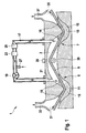
- the single figure shows a schematic representation of the device according to the invention.
- An inventive device 1 as in FIG. 1 comprises a reaction space 3, in which a different gas or gas mixture is contained from the surrounding atmosphere. In order to obtain a uniform atmosphere in the entire reaction space 3, the reaction chamber 3 is flowed through by the gas or gas mixture.
- the reaction space 3 comprises an inlet 5 and an outlet 7.
- a strand-shaped product 9 is fed to the reaction space 3 via the inlet 5.
- the strand-shaped product 9 is exposed to the gas or gas mixture contained in the reaction space 3.
- the rope-shaped product 9 is e.g. a profile of an elastomeric material, such as is used for wiper rubbers of windshield wipers. This is halogenated to harden the elastomeric material in the reaction space 3.
- the gas contained in the reaction space 3 is preferably a gas mixture of at least one halogen and optionally nitrogen.
- the halogens used are usually chlorine, fluorine or bromine or mixtures thereof.
- a first siphon 11 is formed in the region of the inlet 5 and a second siphon 13 is formed in the region of the outlet 7.
- the first siphon 11 and the second siphon 13 are preferably in the form of a substantially U-shaped tube.
- any other geometric shape is also conceivable which makes it possible to fill the first siphon 11 and the second siphon 13 with a liquid 15 such that at least a portion of the tubular siphon 11, 13 is completely filled with the liquid 15 without there being a gas layer above the liquid 15.
- any liquid 15 is suitable, which is inert to both the environment and the gas contained in the reaction space 3.
- water is used as the liquid 15 in the first siphon 11 and in the second siphon 13.
- the gas circulation 17 preferably branches off from the reaction space 3 at a position in the vicinity of the outlet 7. At this position, gas is sucked from the reaction space 3 into the gas circulation 17.
- a fan 19 is contained in the gas circulation 17, through which the gas flow in the gas circulation 17 is maintained.
- the gas circulation 17 opens in the reaction chamber 3.
- the mouth region 21 of the gas circulation 17 is formed for example in the form of a nozzle. Any nozzle known to a person skilled in the art is suitable here. But it is also possible to make the mouth region 21 as a pipe end of the gas circulation 17.
- the training as a nozzle is not essential. The advantage of a nozzle, however, is that a higher gas velocity is achieved and thus a better blowing of the rope-shaped product 9 is made possible.
- a device for gas drying 23 is preferably included in the gas circulation 17.
- a device for gas drying 23 any, known in the art device is suitable.
- a device for gas drying 23 e.g. an adsorption dryer or an absorption dryer can be used.
- halogen is consumed from the gas contained in the reaction space 3.
- a device 25 for analyzing the gas composition is contained in the gas circulation 17.
- analysis of the gas composition e.g. UV / Vis spectroscopy or Raman spectroscopy.
- the apparatus 25 for analyzing the gas composition preferably carries out a continuous measurement of the composition of the gas flowing through the gas circulation 17 in the reaction space 3 or the gas.
- fresh gas is supplied to the gas circulation 17 or the reaction space 3.
- a halogen-rich gas mixture is supplied as fresh gas.
- the halogen-rich gas mixture contains only the constituents which are also contained in the gas mixture in the reaction space 3.
- the proportion of the consumed halogen in the supplied fresh gas is higher than the proportion of halogen in the reaction space 3.
- the amount of fresh gas supplied is chosen so that a constant composition of the gas is achieved in the reaction space.
- the supply of the fresh gas takes place e.g. via an inlet 27 in the gas circulation 17 or alternatively via an inlet not shown in the figure directly into the reaction space 3.
- the inlet 27 is arranged on the gas circulation 17.
- the pressure in the reaction space 3 preferably corresponds to atmospheric pressure.
- a pressure control is provided on the reaction space 3. This includes, for example, a pressure relief valve 29, which opens as soon as the pressure in the reaction chamber 3 the predetermined Pressure exceeds. But it is also any other, known in the art pressure control possible, with which the pressure in the reaction chamber 3 can be kept constant.
- the liquid level in the siphons 11, 13 In order to avoid that gas can escape from the reaction chamber 3 to the environment, it is also necessary to keep the liquid level in the siphons 11, 13 substantially constant. In particular, care must be taken to ensure that a subregion of the siphon 11, 13 is always completely filled with liquid, without a gas layer forming above the liquid. A constant loss of fluid in the siphons 11, 13 is caused on the one hand by evaporation at the liquid surfaces 16 as well as by entrainment of liquid with the rope-shaped product 9. This loss of fluid must be compensated. This can e.g. be effected in that the siphons 11, 13 are connected to a reservoir, is kept in the liquid. About the reservoir, the fluid level in the siphons 11, 13 can be controlled automatically. Thus, the siphons 11, 13, e.g. Liquid level monitoring and as soon as a minimum liquid level is reached, liquid is tracked.
- a first trigger 33 and in the region of the outlet 35 from the second siphon 13 are preferably arranged in the region of the inlet 31 to the first siphon 11.
- the first trigger 33 and the second trigger 37 are preferably connected to an exhaust gas purification system.
- the entrained gas can be removed in a manner known to those skilled in the art.
- Scrubbers are used for exhaust gas purification.
- the strand-shaped product 9 runs in the region of the first siphon 11 and the second siphon 13 along the wall thereof.
- a deflection roller 39 is accommodated, over which the strand-shaped product 9 is guided.
- the reaction space 3 can be kept short and compact. Rapid halogenation is achieved by using, for example, still existing heat in the elastomer profile by the halogenation takes place immediately after the vulcanization of the elastomer profile. Even when passing the elastomer profile through the liquid 15 in the first siphon 11, only part of the heat is released, so that a still warm elastomer profile enters the reaction space 3.
Landscapes
- Chemical & Material Sciences (AREA)
- Chemical Kinetics & Catalysis (AREA)
- Health & Medical Sciences (AREA)
- Engineering & Computer Science (AREA)
- Plasma & Fusion (AREA)
- General Chemical & Material Sciences (AREA)
- Physics & Mathematics (AREA)
- Medicinal Chemistry (AREA)
- Polymers & Plastics (AREA)
- Organic Chemistry (AREA)
- Addition Polymer Or Copolymer, Post-Treatments, Or Chemical Modifications (AREA)
- Organic Low-Molecular-Weight Compounds And Preparation Thereof (AREA)
- Processing And Handling Of Plastics And Other Materials For Molding In General (AREA)
Abstract
Description
- Die Erfindung betrifft eine Vorrichtung zur Exposition eines strangförmigen Produkts einem Gas gemäß dem Oberbegriff des Anspruchs 1. Weiterhin betrifft die Erfindung ein Verfahren zur Halogenierung von strangförmigen Elastomerprofilen in einer solchen Vorrichtung.
- Um ein Objekt einer gasförmigen Atmosphäre auszusetzen, ist es einerseits möglich, das Objekt in einen Gasstrom einer entsprechenden Zusammensetzung zu bringen. Dies ist jedoch nur möglich, wenn das Gas an die Umgebung abgegeben werden kann. Bei Gasen, die nicht an die Umgebung gelangen dürfen, z.B. bei toxischen Gasen oder umweltschädlichen Gasen, ist es notwendig, einen geschlossenen Raum vorzusehen. Im Allgemeinen wird der Raum mit dem Gas geflutet und das dem Gas auszusetzende Objekt in den Raum positioniert.
- Insbesondere bei kontinuierlich ablaufenden Prozessen, z.B. bei Strangerzeugnissen, die einer gasförmigen Atmosphäre einer beliebigen Zusammensetzung ausgesetzt werden sollen, ergibt sich das Problem, dass das Erzeugnis der Kammer zugeführt und aus der Kammer wieder abgeführt werden muss. Am Einlass bzw. Auslass des strangförmigen Objekts muss eine Dichtung vorgesehen sein, die ein Austreten des Gases aus der Kammer verhindert. Da derartige gasundurchlässige Dichtungen jedoch nur schwer zu realisieren sind, werden im Allgemeinen strangförmige Erzeugnisse chargenweise in eine Reaktionskammer eingelegt, die anschließend verschlossen und dann mit dem entsprechenden Gas geflutet wird. Nach der Behandlung wird zunächst das Gas aus der Kammer entfernt, bevor diese wieder geöffnet wird, um das Produkt herauszunehmen.
- Produkte, die einer Gasbehandlung ausgesetzt werden, sind z.B. strangförmige Elastomerprofile, wie sie beispielsweise als Wischgummis für Scheibenwischer eingesetzt werden. Diese werden im Allgemeinen halogeniert. Hierzu wird das Wischgummi einem Halogen, im Allgemeinen Chlor, für eine bestimmte Zeitdauer ausgesetzt. Dies erfolgt z.B. in einem Reaktor, in den das Wischprofil eingelegt wird und der anschließend von einem Halogen durchströmt wird. Ein solcher Reaktor ist z.B. aus
JP 61 042 506 - Vorteile der Erfindung
- Eine erfindungsgemäße Vorrichtung zur Exposition eines strangförmigen Produkts einem Gas umfasst einen Reaktionsraum, in dem das Gas enthalten ist, mit einem Einlass, durch den das strangförmige Produkt kontinuierlich dem Reaktionsraum zugeführt wird und einem Auslass, durch den das strangförmige Produkt aus dem Reaktionsraum austritt. Am Einlass und am Auslass ist jeweils ein mit einer Flüssigkeit gefüllter Syphon ausgebildet, durch das das strangförmige Produkt geführt wird.
- Der mit einer Flüssigkeit gefüllte Syphon dichtet das Innere des Reaktionsraums im Bereich des Einlasses und Auslasses des strangförmigen Produkts gegen die Umgebung ab. Hierdurch wird vermieden, dass aus dem Reaktionsraum Gas austreten kann. Gleichzeitig ermöglicht der Syphon einen kontinuierlichen Durchlauf des strangförmigen Produkts durch den Reaktionsraum.
- Im Allgemeinen weist eine Flüssigkeit in einem Syphon eine freie Oberfläche zur Umgebung hin auf. An der freien Oberfläche kann Flüssigkeit bis zum Erreichen der Sättigungsgrenze der Flüssigkeit in der Gasatmosphäre verdunsten. Aus diesem Grund kann sich auch Flüssigkeit im Reaktionsraum anreichern, bis die Sättigungsgrenze der Flüssigkeit erreicht ist. Um die verdunstete Flüssigkeit aus dem Gas zu entfernen, ist es bevorzugt, den Reaktionsraum mit einem Gastrockner zu verbinden. Das Gas wird dem Gastrockner zugeführt und in diesem getrocknet. Hierdurch wird im Gas enthaltene Flüssigkeit entfernt.
- In einer bevorzugten Ausführungsform ist der Reaktionsraum mit einem Gasumlauf verbunden, durch den das im Reaktionsraum enthaltene Gas umgewälzt wird. Vorteil des Gasumlaufs ist, dass eine gleichmäßige Durchmischung des Gases erfolgt und die Atmosphäre im gesamten Reaktionsraum eine im Wesentlichen konstante Zusammensetzung aufweist.
- Wenn mindestens eine Komponente des Gases im Reaktionsraum z.B. durch eine chemische Reaktion mit dem strangförmigen Produkt verbraucht wird, ist es z.B. möglich, eine Vorrichtung zur Analyse der Gaszusammensetzung vorzusehen. Bei einem Gasumlauf ist die Vorrichtung zur Analyse der Gaszusammensetzung vorzugsweise im Gasumlauf angeordnet. Auch der Gastrockner, in dem Feuchtigkeit aus dem Gas entfernt werden kann, ist vorzugsweise im Gasumlauf angeordnet. Auf diese Weise erfolgt im Gasumlauf eine Konditionierung des dem Reaktionsraum zugeführten Gases.
- In einer weiteren bevorzugten Ausführungsform ist weiterhin eine Vorrichtung zur Zudosierung von Gas umfasst. Entsprechend dem Gasverbrauch im Reaktionsraum kann auf diese Weise verbrauchtes Gas nachdosiert werden. Zur Nachdosierung kann dem Reaktionsraum entweder Reingas zugeführt werden oder aber ein Gasgemisch, das zwei oder mehr Komponenten des im Reaktionsraum enthaltenen Gases enthält. Wenn ein Gasgemisch zugeführt wird, ist es bevorzugt, dass die mindestens eine Komponente, die z.B. durch die chemische Reaktion verbraucht wird, in einer höheren Konzentration enthalten ist als die Konzentration dieses Gases im Reaktionsraum. Auf diese Weise kann die Konzentration des Gases im Reaktionsraum erhöht werden.
- Die Vorrichtung zur Zudosierung von Gas kann entweder mit dem Reaktionsraum oder alternativ mit dem Gasumlauf verbunden sein. Bevorzugt ist die Vorrichtung zur Dosierung von Gas mit dem Gasumlauf verbunden. Die Menge an zuzuführendem Gas kann z.B. durch Analyse der Gaszusammensetzung ermittelt werden.
- Im Allgemeinen kann sich Gas aus dem Reaktionsraum in der Flüssigkeit, die im Syphon enthalten ist, lösen. Hierdurch reichert sich Gas in der Flüssigkeit an. Da die Flüssigkeit auch auf der dem Reaktionsraum abgewandten Seite eine freie Oberfläche aufweist, mit der diese in Kontakt zur Umgebung steht, kann auch auf der dem Reaktionsraum abgewandten Seite Flüssigkeit aus dem Syphon verdunsten. Wenn sich in der Flüssigkeit Gas gelöst hat, so tritt mit der verdunstenden Flüssigkeit ebenfalls Gas an die Atmosphäre aus. Um zu vermeiden, dass dieses Gas in die Umgebung gelangt, ist es bevorzugt, auf der dem Reaktionsraum abgewandten Seite der Syphons am Einlass und am Auslass jeweils eine Absaugung anzuordnen, um verdunstende gashaltige Flüssigkeit aus dem Syphon abzusaugen. Das mit der Absaugung abgesaugte Flüssigkeit enthaltende Gas kann z.B. einer Aufbereitungsvorrichtung zugeführt werden. Alternativ ist es auch möglich, das Gas z.B. einer Gaswäsche zuzuführen, in der unerwünschte Bestandteile aus dem Gas entfernt werden, bevor dieses als Abluft an die Umgebung abgegeben wird. Zur Abgasreinigung können z.B. Wäscher, Filter oder jede beliebige andere Vorrichtung zur Abgasreinigung, die dem Fachmann bekannt ist, eingesetzt werden.
- Die Flüssigkeit, die in den Syphons enthalten ist, wird vorzugsweise so ausgewählt, dass diese gegenüber dem im Reaktionsraum enthaltenen Gas inert ist. Eine geeignete Flüssigkeiten, die in den Syphons enthalten ist, ist z.B. Wasser.
- Alternativ ist es jedoch auch möglich, dass z.B. Flüssigkeiten eingesetzt werden, die das im Reaktionsraum enthaltene Gas, das sich in der Flüssigkeit löst, binden können, um zu verhindern, dass das Gas aus der Flüssigkeit an die Umgebung durch verdunstende Flüssigkeit austreten kann.
- Der Flüssigkeitsstand in den Syphons kann z.B. durch Verdunstung von Flüssigkeit in den Reaktionsraum bzw. an die Umgebung sowie durch Mitreißen von Flüssigkeit mit dem strangförmigen Produkt, welches durch die Flüssigkeit geführt wird, abnehmen. Aus diesem Grund ist es bevorzugt, eine Vorrichtung vorzusehen, mit der die im Syphon enthaltene Flüssigkeit ergänzt werden kann. Hierzu ist es z.B. möglich, einen Vorratsbehälter vorzusehen, der mit den jeweiligen Syphons verbunden ist. Zur Zufuhr von Flüssigkeit kann z.B. in der Verbindung vom Vorratsbehälter in den Syphon eine Pumpe vorgesehen sein. Alternativ ist es jedoch auch möglich, den Flüssigkeitsstand im Vorratsbehälter so zu wählen, dass automatisch Flüssigkeit bis zu einem vorgegebenen Flüssigkeitsstand in den Syphon nachgeführt wird. Auf diese Weise wird der Flüssigkeitsstand im Syphon im Wesentlichen konstant gehalten.
- Die Erfindung betrifft weiterhin ein Verfahren zur Halogenierung von strangförmigen Elastomerprofilen in der erfindungsgemäßen Vorrichtung. Hierbei wird das strangförmige Elastomerprofil durch die Flüssigkeit im Syphon am Einlass dem Reaktionsraum zugeführt und durch die Flüssigkeit im Syphon am Auslass aus dem Reaktionsraum abgezogen. Im Reaktionsraum ist ein halogenhaltiges Gas enthalten.
- Das strangförmige Elastomerprofil ist z.B. ein Profil, wie es für Wischgummis von Scheibenwischern eingesetzt wird. Durch die Reaktion mit einem Halogen wird das Elastomer des Elastomerprofils gehärtet. Typischerweise eingesetzte Elastomere sind z.B. Naturkautschuk (NR), Chloropen-Kautschuk (CR), Butadien-Kautschuk (BR), Stryrol-Butadien-Kautschuk (SBR), Ethylen-Propylen-Copolymer (EPM), Ethylen-Propylen-Dien-Terpolymer (EPDM), Ethylen-Vinylacetat-Copoylmere (EVM), Acrylnitril-Butadien-Kautschuk (NBR), hydrierter Acrylnitril-Butadien-Kautschuk (HNBR), Polyurethan-Elastomere (PUR) sowie Mischungen aus diesen Materialien.
- Besonders bevorzugt ist das Elastomermaterial ausgewählt aus Ethylen-Propylen-Dien-Terpolymer, Naturkautschuk, Chloropren-Kautschuk oder einer Mischung daraus.
- Das im Reaktionsraum enthaltene halogenhaltige Gas enthält z.B. Chlor, Fluor oder Brom. Ggf. ist weiterhin Stickstoff enthalten. Der Anteil an Halogen im Gas liegt vorzugsweise im Bereich von 10 bis 100 Vol.-%. Im Reaktionsraum kann nur ein Halogen oder eine Mischung aus zwei oder mehr Halogenen enthalten sein. Wenn eine Mischung aus zwei oder mehr Halogenen enthalten ist, so liegt der Anteil an Chlor vorzugsweise im Bereich von 5 bis 50 Vol.-%, der Anteil an Fluor im Bereich von 1 bis 10 Vol.-% und der Anteil an Brom im Bereich von 5 bis 50 Vol.-%.
- Insbesondere, wenn neben Halogen im Gasgemisch auch mindestens ein inertes Gas oder im Gas eine Mischung aus zumindest zwei Halogenen enthalten ist, wird der Halogengehalt des Gases kontinuierlich gemessen und verbrauchtes Halogen durch Zugabe eines halogenhaltigen Gas ergänzt. Auf diese Weise kann die Zusammensetzung des Gasgemisches im Wesentlichen konstant gehalten werden. Neben einem halogenreichen Gas, das zugeführt wird, ist es auch möglich, reines Halogen zuzuführen. Wenn ein halogenreiches Gas ergänzt wird, so enthält dieses lediglich Komponenten, die auch im Gasgemisch, das im Reaktionsraum enthalten ist, enthalten sind.
- Der Reaktionsraum wird vorzugsweise von dem halogenhaltigen Gas durchströmt. Um den Reaktionsraum mit dem halogenhaltigen Gas zu durchströmen, ist es bevorzugt, den Reaktionsraum mit einem Gasumlauf zu versehen, durch den das halogenhaltige Gas geführt wird. Hierzu ist im Gasumlauf vorzugsweise ein Gebläse vorgesehen. Der Gasumlauf mündet z.B. mit einer Düse im Reaktionsraum. Hierdurch lässt sich das strangförmige Produkt direkt mit dem Gas anblasen. Alternativ ist es jedoch auch möglich, dass der Gasumlauf an einer beliebigen Position im Reaktionsraum endet und das Gas an dieser Stelle in den Reaktionsraum eintritt. Durch die Durchströmung des Reaktionsraumes mit dem Gas wird gewährleistet, dass die Gaszusammensetzung im Reaktionsraum im Wesentlichen konstant bleibt. Die Zusammensetzung des Gases wird vorzugsweise mit einer Vorrichtung zur Analyse der Gaszusammensetzung kontinuierlich erfasst. Hierbei eignet sich jede beliebige, dem Fachmann bekannte Vorrichtung zur Analyse der Gaszusammensetzung. Geeignete Vorrichtungen, um die Zusammensetzung des Gases zu analysieren, sind z.B. UV/Vis-Spektroskopie oder auch Raman-Spektroskopie.
- Weiterhin wird das halogenhaltige Gas vorzugsweise getrocknet. Dies erfolgt z.B. durch einen im Gasumlauf enthaltenen Gastrockner. Die Trocknung kann durch jedes beliebige, dem Fachmann bekannte Verfahren erfolgen. So kann z.B. ein Adsorptionstrockner eingesetzt werden.
- Die Trocknung des halogenhaltigen Gases ist erforderlich, um die von dem Elastomerprofil in den Reaktionsraum eingeschleppte Flüssigkeit zu entfernen. Die Entfernung der Flüssigkeit erfolgt z.B. indem diese im Reaktionsraum verdunstet. Eine schnelle Trocknung wird erzielt, indem das Elastomerprofil nach passieren des am Einlass angeordneten Syphons von dem getrockneten halogenhaltigen Gas angeblasen wird.
- Um zu vermeiden, dass aus dem Reaktionsraum Gas durch den Syphon am Einlass bzw. am Auslass herausgedrückt wird, ist es erforderlich, dass auf beiden Seiten des Syphons im Wesentlichen gleicher Druck vorliegt. Besonders bevorzugt herrscht im Reaktionsraum Atmosphärendruck. Alternativ ist es möglich, im Reaktionsraum einen Druck bereitzuhalten, der unterhalb des äußeren Drucks, insbesondere unterhalb des Atmosphärendrucks, liegt. Auch diese Weise kann vermieden werden, dass Gas über den Syphon austreten kann. Jedoch kann ein zu großer Druckunterschied dazu führen, dass Gas aus der Umgebung über den Syphon in den Reaktionsraum eindringt.
- Durch den Flüssigkeitsstand in den Syphons lässt sich die Zudosierung beziehungsweise Nachdosierung des Gases regeln. Die Differenz des Flüssigkeitsstands der zur Umgebung weisenden Seite des Syphons und der zum Reaktionsraum weisenden Seite des Syphons entspricht jeweils der Differenz des Druckes im Reaktionsraum zum äußeren Atmosphärendruck. Sobald der Flüssigkeitsstand an der zur Umgebung weisenden Seite des Syphons abnimmt und der Flüssigkeitsstand auf der zum Reaktionsraum weisenden Seite des Syphons zunimmt, nimmt der Druck im Reaktionsraum ab, es muss Gas nachgeführt werden.
- Insbesondere bei der Halogenierung von strangförmigen Elastomerprofilen, wie sie beispielsweise für Wischgummis von Scheibenwischern eingesetzt werden, ist es bevorzugt, eine schnelle Reaktion des Halogens mit dem Elastomer zu erreichen und so den Reaktionsraum möglichst kurz und kompakt halten zu können. Um dies zu erreichen, ist es bevorzugt, die Halogenierung unmittelbar nach der Vulkanisation des Elastomerprofils durchzuführen. Auf diese Weise wird die im Elastomerprofil noch vorhandene Wärme für eine Beschleunigung der Reaktion bei der Halogenierung genutzt. Hierbei ist jedoch zu berücksichtigen, dass das Elastomerprofil beim Durchlauf durch den Syphon abgekühlt wird. Die Temperatur des Elastomerprofils im Reaktionsraum ist somit niedriger als die Temperatur vor dem Eintritt in die Flüssigkeit des Syphons auf der Einlassseite.
- Alternativ ist es auch möglich, mit einem erwärmten Gasgemisch zu arbeiten. Das Gas kann z.B. im Gasumlauf aufgewärmt werden. Hierzu lässt sich z.B. ein Wärmeübertrager verwenden. Alternativ ist es z.B. auch möglich, dass das Gas in der Vorrichtung zum Trocknen des Gases erwärmt wird.
- Auch ist es möglich, die in den Syphons enthaltene Flüssigkeit zu beheizen. Hierdurch wird das strangförmige Elastomerprofil weniger stark abgekühlt, woraus insbesondere bei einer Reaktion der Oberfläche des Elastomerprofils mit Chlor ebenfalls ein positiver Effekt auf die Reaktionsgeschwindigkeit resultiert. Ein weiterer Vorteil, der sich aus dem Beheizen der Flüssigkeit ergibt, ist zum Beispiel, dass die Löslichkeit von im Reaktionsraum enthaltenem Halogen, beispielsweise Chlor, gering gehalten wird.
- Weiterhin ist es auch möglich, z.B. die Dissoziation des Halogens mit einem kalten Plasma zu unterstützen.
- Eine Ausführungsform der Erfindung ist in der Zeichnung dargestellt und in der nachfolgenden Beschreibung näher erläutert.
- Die einzige Figur zeigt eine schematische Darstellung der erfindungsgemäßen Vorrichtung.
- Eine erfindungsgemäß Vorrichtung 1 wie sie in
Figur 1 dargestellt ist, umfasst einen Reaktionsraum 3, in dem ein von der umgebenden Atmosphäre verschiedenes Gas oder Gasgemisch enthalten ist. Um im gesamten Reaktionsraum 3 eine gleichmäßige Atmosphäre zu erhalten, ist der Reaktionsraum 3 von dem Gas oder Gasgemisch durchströmt. - Der Reaktionsraum 3 umfasst einen Einlass 5 und einen Auslass 7. Über den Einlass 5 wird dem Reaktionsraum 3 ein strangförmiges Produkt 9 zugeführt. Im Reaktionsraum 3 wird das strangförmige Produkt 9 dem im Reaktionsraum 3 enthaltenen Gas bzw. Gasgemisch ausgesetzt.
- Das strangförmige Produkt 9 ist z.B. ein Profil aus einem Elastomermaterial, wie es beispielsweise für Wischgummis von Scheibenwischern eingesetzt wird. Dieses wird zur Härtung des Elastomermaterials im Reaktionsraum 3 halogeniert. Hierzu ist das im Reaktionsraum 3 enthaltene Gas vorzugsweise ein Gasgemisch aus mindestens einem Halogen und ggf. Stickstoff. Als Halogene werden üblicherweise Chlor, Fluor oder Brom oder Mischungen daraus eingesetzt.
- Um zu vermeiden, dass Gas aus dem Reaktionsraum 3 austritt, ist im Bereich des Einlasses 5 ein erster Syphon 11 und im Bereich des Auslasses 7 ein zweiter Syphon 13 ausgebildet.
- Der erste Syphon 11 und der zweite Syphon 13 sind vorzugsweise in Form eines im Wesentlichen U-förmigen Rohres ausgebildet. Es ist aber auch jede beliebige andere geometrische Form denkbar, die es ermöglicht, den ersten Syphon 11 und den zweiten Syphon 13 so mit einer Flüssigkeit 15 zu befüllen, dass zumindest ein Teilbereich des rohrförmig ausgebildeten Syphons 11, 13 vollständig mit der Flüssigkeit 15 befüllt ist, ohne dass sich oberhalb der Flüssigkeit 15 eine Gasschicht befindet. Als Flüssigkeit, mit der der erste Syphon 11 bzw. zweite Syphon 13 befüllt sind, eignet sich jede beliebige Flüssigkeit 15, die sowohl gegenüber der Umgebung als auch dem im Reaktionsraum 3 enthaltenen Gas inert ist. Weiterhin ist es bevorzugt, schwer flüchtige Flüssigkeiten einzusetzen, um die Verdunstungsmenge der Flüssigkeit 15 gering zu halten. Bevorzugt als Flüssigkeit 15 im ersten Syphon 11 und im zweiten Syphon 13 wird Wasser eingesetzt. Dies hat den Vorteil, dass es günstig ist und in ausreichend großer Menge zur Verfügung steht, um Flüssigkeitsverluste im ersten Syphon 11 und zweiten Syphon 13 kontinuierlich ausgleichen zu können, um einen im Wesentlichen gleichmäßigen Flüssigkeitsstand im ersten Syphon 11 und im zweiten Syphon 13 zu gewährleisten. Flüssigkeitsverluste in den Syphons 11, 13 treten z.B. durch Verdunstung an der Flüssigkeitsoberfläche 16 und durch Mitschleppen von Flüssigkeit 15 am strangförmigen Produkt 9 auf. Durch das strangförmige Produkt 9 wird Flüssigkeit 15 sowohl in den Reaktionsraum 3 über den ersten Syphon 11 am Einlass 5 eingeschleppt als auch aus dem zweiten Syphon 13 beim Verlassen des Reaktionsraums 3 ausgetragen.
- Insbesondere, wenn eine Reaktion der Oberfläche des strangförmigen Produkts 9 mit einem im Reaktionsraum 3 enthaltenen Gas erfolgen soll, z.B. bei der Halogenierung eines Elastomerprofils, ist es notwendig, das strangförmige Produkt 9 nach dem Durchlaufen des ersten Syphons 11 zu trocknen, damit ein gleichmäßiger Kontakt der Oberfläche des strangförmigen Produkts 9 mit dem im Reaktionsraum 3 enthaltenen Gas erfolgen kann. Eine schnelle Trocknung wird z.B. dadurch erreicht, dass das strangförmige Produkt 9 nach dem Durchlaufen des ersten Syphons 11 angeblasen wird. Dies erfolgt vorzugsweise mit dem im Reaktionsraum 3 enthaltenen Gas. Um den Druck im Reaktionsraum 3 konstant zu halten und das strangförmige Produkt 9 gleichmäßig mit dem Gas anblasen zu können, ist es bevorzugt, einen Gasumlauf 17 vorzusehen. Der Gasumlauf 17 zweigt vorzugsweise an einer Position in der Nähe des Auslasses 7 aus dem Reaktionsraum 3 ab. An dieser Position wird Gas aus dem Reaktionsraum 3 in den Gasumlauf 17 angesaugt. Hierzu ist im Gasumlauf 17 ein Gebläse 19 enthalten, durch das die Gasströmung im Gasumlauf 17 aufrechterhalten wird. Im Bereich des Einlasses 5 für das strangförmige Produkt 9 mündet der Gasumlauf 17 im Reaktionsraum 3. Um das strangförmige Produkt 9 mit dem durch den Gasumlauf 17 strömenden Gas anzublasen, ist der Mündungsbereich 21 des Gasumlaufs 17 z.B. in Form einer Düse ausgebildet. Hierbei eignet sich jede beliebige, dem Fachmann bekannte Düse. Es ist aber auch möglich, den Mündungsbereich 21 als Rohrende des Gasumlaufs 17 zu gestalten. Die Ausbildung als Düse ist nicht unbedingt erforderlich. Vorteil einer Düse ist jedoch, dass eine höhere Gasgeschwindigkeit erreicht wird und damit ein besseres Anblasen des strangförmigen Produkts 9 ermöglicht wird.
- Durch das Trocknen des strangförmigen Produkts 9 wird das im Reaktionsraum 3 enthaltene Gas befeuchtet. Zudem verdunstet ein Teil der Flüssigkeit an der Flüssigkeitsoberfläche 16, wodurch ebenfalls die Feuchte des im Reaktionsraum 3 enthaltenen Gases erhöht wird. Die so vom Gas aufgenommene Flüssigkeit muss wieder aus dem Gas entfernt werden. Hierzu ist vorzugsweise im Gasumlauf 17 eine Vorrichtung zu Gastrocknung 23 aufgenommen. Als Vorrichtung zur Gastrocknung 23 eignet sich jede beliebige, dem Fachmann bekannte Vorrichtung. So kann als Vorrichtung zur Gastrocknung 23 z.B. ein Adsorptionstrockner oder ein Absorptionstrockner eingesetzt werden.
- Insbesondere bei der Halogenierung von Elastomerprofilen wird Halogen aus dem im Reaktionsraum 3 enthaltenen Gas verbraucht. Um eine gleichmäßige Halogenierung zu gewährleisten, ist es jedoch erforderlich, eine im Wesentlichen gleich bleibende Zusammensetzung des Gases im Reaktionsraum 3 bereitzustellen. Hierzu ist im Gasumlauf 17 eine Vorrichtung 25 zur Analyse der Gaszusammensetzung enthalten. Zur Analyse der Gaszusammensetzung eignen sich z.B. UV/Vis-Spektroskopie oder auch Raman-Spektroskopie.
- Mit der Vorrichtung 25 zur Analyse der Gaszusammensetzung erfolgt vorzugsweise eine kontinuierliche Messung der Zusammensetzung des im Reaktionsraum 3 bzw. des durch den Gasumlauf 17 strömenden Gases. Entsprechend der Gaszusammensetzung wird dem Gasumlauf 17 oder dem Reaktionsraum 3 frisches Gas zugeführt. Wenn die Vorrichtung 1 zur Halogenierung eines Elastomerprofils eingesetzt wird, so wird als frisches Gas ein halogenreiches Gasgemisch zugeführt. Das halogenreiche Gasgemisch enthält dabei lediglich die Bestandteile, die auch im Gasgemisch im Reaktionsraum 3 enthalten sind. Jedoch ist der Anteil des verbrauchten Halogens im zugeführten Frischgas höher als der Anteil des Halogens im Reaktionsraum 3. Die Menge des zugeführten Frischgases wird dabei so gewählt, dass eine konstante Zusammensetzung des Gases im Reaktionsraum erzielt wird. Die Zufuhr des Frischgases erfolgt z.B. über einen Zulauf 27 im Gasumlauf 17 oder alternativ über einen in der Figur nicht dargestellten Zulauf direkt in den Reaktionsraum 3. Bevorzugt ist jedoch der Zulauf 27 am Gasumlauf 17 angeordnet.
- Um zu vermeiden, dass Gas aus dem Reaktionsraum 3 über die Syphons 11, 13 herausgedrückt wird, entspricht der Druck im Reaktionsraum 3 vorzugsweise Atmosphärendruck. Hierzu ist am Reaktionsraum 3 eine Druckregelung vorgesehen. Diese umfasst beispielsweise ein Überdruckventil 29, welches öffnet, sobald der Druck im Reaktionsraum 3 den vorgegebenen Druck übersteigt. Es ist aber auch jede beliebige andere, dem Fachmann bekannte Druckregelung möglich, mit der der Druck im Reaktionsraum 3 konstant gehalten werden kann.
- Um zu vermeiden, dass Gas aus dem Reaktionsraum 3 an die Umgebung austreten kann, ist es weiterhin erforderlich, den Flüssigkeitsstand in den Syphons 11, 13 im Wesentlichen konstant zu halten. Insbesondere ist darauf zu achten, dass ein Teilbereich des Syphons 11, 13 immer vollständig mit Flüssigkeit befüllt ist, ohne dass sich eine Gasschicht oberhalb der Flüssigkeit ausbildet. Ein ständiger Flüssigkeitsverlust in den Syphons 11, 13 entsteht zum einen durch Verdunstung an den Flüssigkeitsoberflächen 16 als auch durch Mitschleppen von Flüssigkeit mit dem strangförmigen Produkt 9. Dieser Flüssigkeitsverlust muss ausgeglichen werden. Dies kann z.B. dadurch erfolgen, dass die Syphons 11, 13 mit einem Vorratsbehälter verbunden sind, in dem Flüssigkeit vorgehalten wird. Über den Vorratsbehälter lässt sich der Flüssigkeitsstand in den Syphons 11, 13 automatisch regeln. So können die Syphons 11,13 z.B. eine Flüssigkeitsstandüberwachung umfassen und sobald ein minimaler Flüssigkeitsstand erreicht wird, wird Flüssigkeit nachgeführt.
- Da sich im Allgemeinen auch Gas in der Flüssigkeit löst, wird sich Gas aus dem Reaktionsraum 3 bis zum Erreichen der Sättigungsgrenze in der Flüssigkeit 15 in den Syphons 11, 13 lösen. Bei der Verdunstung über die Flüssigkeitsoberfläche 16 geht somit auch Gas in die Atmosphäre. Um zu vermeiden, dass das Gas an die Umgebung abgegeben wird, ist vorzugsweise im Bereich des Zulaufs 31 zum ersten Syphon 11 ein erster Abzug 33 und im Bereich des Ablaufs 35 aus dem zweiten Syphon 13 ein zweiter Abzug 37 angeordnet. Der erste Abzug 33 und der zweite Abzug 37 sind vorzugsweise mit einer Abgasreinigung verbunden. In der Abgasreinigung kann das mitgerissene Gas auf dem Fachmann bekannte Weise entfernt werden. So können zur Abgasreinigung z.B. Wäscher eingesetzt werden.
- In der hier dargestellten Ausführungsform läuft das strangförmige Produkt 9 im Bereich des ersten Syphons 11 und des zweiten Syphons 13 an dessen Wandung entlang. Im Reaktionsraum 3 ist eine Umlenkrolle 39 aufgenommen, über die das strangförmige Produkt 9 geführt ist. Um zu vermeiden, dass das strangförmige Produkt 9 im Bereich des ersten Syphons 11 und des zweiten Syphons 13 an dessen Wandung entlangläuft, ist es auch möglich, in den Syphons 11, 13 Umlenkrollen vorzusehen, über die strangförmige Produkt 9 geführt wird. Ein Führen entlang der Wandung des Syphons 11, 13 ist möglich, da die im Syphon 11, 13 enthaltene Flüssigkeit 15 als Schmierfilm an der Wandung wirkt.
- Insbesondere bei der Halogenierung von Elastomerprofilen ist es vorteilhaft, die Halogenierung bei erhöhter Temperatur durchzuführen, um eine schnelle Reaktion des Halogens mit dem Elastomer zu erreichen. Durch die schnelle Reaktion kann der Reaktionsraum 3 kurz und kompakt gehalten werden. Eine schnelle Halogenierung wird dadurch erreicht, dass z.B. im Elastomerprofil noch vorhandene Wärme genutzt wird, indem die Halogenierung unmittelbar nach der Vulkanisation des Elastomerprofils erfolgt. Auch beim Durchleiten des Elastomerprofils durch die Flüssigkeit 15 im ersten Syphon 11 wird nur ein Teil der Wärme abgegeben, so dass ein noch warmes Elastomerprofil in den Reaktionsraum 3 eintritt.
- Alternativ ist es jedoch auch möglich, z.B. mit einem erwärmten Gas im Reaktionsraum 3 zu arbeiten. Die Erwärmung des Gases erfolgt dabei vorzugsweise ebenfalls im Gasumlauf 17. Weiterhin ist es auch möglich, die Dissoziation des Halogens mit einem kalten Plasma zu unterstützen.
Claims (12)
- Vorrichtung zur Exposition eines strangförmigen Produktes (9) einem Gas, umfassend einen Reaktionsraum (3), in dem das Gas enthalten ist, mit einem Einlass (5), durch den das strangförmige Produkt (9) kontinuierlich dem Reaktionsraum (3) zugeführt wird und einem Auslass (7), durch den das strangförmige Produkt (9) aus dem Reaktionsraum (3) austritt, dadurch gekennzeichnet, dass am Einlass (5) und am Auslass (7) jeweils ein mit einer Flüssigkeit (15) gefüllter Syphon (11, 13) ausgebildet ist, durch den das strangförmige Produkt (9) geführt wird.
- Vorrichtung gemäß Anspruch 1, dadurch gekennzeichnet, dass der Reaktionsraum (3) mit einem Gasumlauf (17) verbunden ist, durch den das im Reaktionsraum (3) enthaltene Gas umgewälzt wird.
- Vorrichtung gemäß Anspruch 2, dadurch gekennzeichnet, dass der Gasumlauf (17) einen Gastrockner umfasst, in dem das umgewälzte Gas getrocknet wird.
- Vorrichtung gemäß Anspruch 2 oder 3, dadurch gekennzeichnet, dass der Gasumlauf (17) eine Vorrichtung (25) zur Analyse der Gaszusammensetzung umfasst.
- Vorrichtung gemäß einem der Ansprüche 1 bis 4, dadurch gekennzeichnet, dass eine Vorrichtung (27) zur Zudosierung von Gas umfasst ist.
- Vorrichtung gemäß Anspruch 5, dadurch gekennzeichnet, dass die Vorrichtung (27) zur Zudosierung von Gas mit dem Gasumlauf (17) verbunden ist.
- Vorrichtung gemäß einem der Ansprüche 1 bis 6, dadurch gekennzeichnet, dass auf der dem Reaktionsraum (3) abgewandten Seite der Syphons (11, 13) am Einlass (5) und am Auslass (7) jeweils eine Absaugung (33, 37) angeordnet ist, um verdunstende gashaltige Flüssigkeit aus dem Syphon abzusaugen.
- Vorrichtung gemäß einem der Ansprüche 1 bis 7, dadurch gekennzeichnet, dass die in den Syphons (11, 13) enthaltene Flüssigkeit (15) Wasser ist.
- Verfahren zur Halogenierung von strangförmigen Elastomerprofilen in einer Vorrichtung gemäß einem der Ansprüche 1 bis 8, bei dem das strangförmige Elastomerprofil (9) durch die Flüssigkeit (15) im Syphon (11) am Einlass (5) dem Reaktionsraum (3) zugeführt wird und durch die Flüssigkeit (15) im Syphon (13) am Auslass (7) aus dem Reaktionsraum (3) abgezogen wird, wobei im Reaktionsraum (3) ein halogenhaltiges Gas enthalten ist.
- Verfahren gemäß Anspruch 9, dadurch gekennzeichnet, dass im Reaktionsraum (3) Atmosphärendruck herrscht.
- Verfahren gemäß Anspruch 9 oder 10, dadurch gekennzeichnet, dass der Halogengehalt des Gases kontinuierlich gemessen wird und verbrauchtes Halogen durch Zugabe eines halogenhaltigen Gases ergänzt wird.
- Verfahren gemäß einem der Ansprüche 9 bis 11, dadurch gekennzeichnet, dass das halogenhaltige Gas Chlor, Fluor oder Brom oder Mischungen daraus und gegebenenfalls Stickstoff enthält.
Applications Claiming Priority (1)
| Application Number | Priority Date | Filing Date | Title |
|---|---|---|---|
| DE102008002393A DE102008002393A1 (de) | 2008-06-12 | 2008-06-12 | Vorrichtung zur Gasexposition |
Related Child Applications (1)
| Application Number | Title | Priority Date | Filing Date |
|---|---|---|---|
| EP14178747 Division-Into | 2014-07-28 |
Publications (3)
| Publication Number | Publication Date |
|---|---|
| EP2133192A2 true EP2133192A2 (de) | 2009-12-16 |
| EP2133192A3 EP2133192A3 (de) | 2009-12-23 |
| EP2133192B1 EP2133192B1 (de) | 2016-03-23 |
Family
ID=41130355
Family Applications (1)
| Application Number | Title | Priority Date | Filing Date |
|---|---|---|---|
| EP09158342.7A Not-in-force EP2133192B1 (de) | 2008-06-12 | 2009-04-21 | Vorrichtung zur Gasexposition |
Country Status (2)
| Country | Link |
|---|---|
| EP (1) | EP2133192B1 (de) |
| DE (1) | DE102008002393A1 (de) |
Families Citing this family (1)
| Publication number | Priority date | Publication date | Assignee | Title |
|---|---|---|---|---|
| DE102017112161A1 (de) | 2017-06-01 | 2018-12-06 | Fluor Technik System Gmbh | Anlage zur kontinuierlichen Behandlung eines Strangprofils |
Citations (1)
| Publication number | Priority date | Publication date | Assignee | Title |
|---|---|---|---|---|
| JPS6142506A (ja) | 1984-08-06 | 1986-03-01 | Mitsui Petrochem Ind Ltd | ハロゲン化反応装置 |
Family Cites Families (14)
| Publication number | Priority date | Publication date | Assignee | Title |
|---|---|---|---|---|
| US2660512A (en) * | 1948-02-06 | 1953-11-24 | R W Webster And Company Ltd | Method and apparatus for controlling the liquid seals on steam sterilizers |
| BE524672A (de) * | 1952-11-29 | 1900-01-01 | ||
| GB898710A (en) * | 1957-10-31 | 1962-06-14 | Polyplastic Sa | Apparatus for preparation of grafted copolymers |
| BE661512A (de) * | 1964-03-25 | 1965-07-16 | ||
| DE2910572A1 (de) * | 1979-03-17 | 1980-09-25 | Kleinewefers Gmbh | Vorrichtung zum fortlaufenden behandeln einer oberflaechenempfindlichen textilbahn, insbesondere zum fixieren von der textilbahn aufgenommenen farbstoffes |
| FR2463833A1 (fr) * | 1979-08-24 | 1981-02-27 | Ivanovsky Inst Khlopchato | Installation pour le traitement thermique continu des materiaux textiles |
| CA1169305A (en) * | 1982-03-03 | 1984-06-19 | Gordon A.D. Reed | Catalytic curing of coatings |
| FR2537014B1 (fr) * | 1982-12-06 | 1987-06-05 | Marchal Equip Auto | Reacteur pour la fixation d'un gaz sur un solide, utilisable notamment pour la chloration de lames racleuses d'essuie-glaces |
| DE3532086A1 (de) * | 1985-09-09 | 1987-03-12 | Lohmann Gmbh & Co Kg | Verfahren zur oberflaechenbehandlung von flaechigem kunststoffmaterial |
| IT233890Y1 (it) * | 1994-05-27 | 2000-02-16 | Attilio Bertoldi | Dispositivo per il trattamento ad umido di tessuti in largo |
| DE19525529C1 (de) * | 1995-07-13 | 1996-06-05 | Koenig & Bauer Albert Ag | Verfahren zur Montage einer Dosiereinrichtung in einer Rotationsdruckmaschine |
| FR2806931B1 (fr) * | 2000-03-30 | 2002-11-15 | Commerciale Prouvost & Lefebvr | Installation et reacteur pour le traitement d'une matiere solide par un gaz ou un melange gazeux nocif |
| ITFI20010188A1 (it) * | 2001-10-10 | 2003-04-10 | C M T S R L Costruzione Macchi | Dispositivo di tenuta in apparecchi a pressione attraversati dal materiale da trattare |
| EP2118395B1 (de) * | 2007-03-01 | 2016-08-17 | Dow Global Technologies LLC | Fluoriertes polymersystem |
-
2008
- 2008-06-12 DE DE102008002393A patent/DE102008002393A1/de not_active Ceased
-
2009
- 2009-04-21 EP EP09158342.7A patent/EP2133192B1/de not_active Not-in-force
Patent Citations (1)
| Publication number | Priority date | Publication date | Assignee | Title |
|---|---|---|---|---|
| JPS6142506A (ja) | 1984-08-06 | 1986-03-01 | Mitsui Petrochem Ind Ltd | ハロゲン化反応装置 |
Also Published As
| Publication number | Publication date |
|---|---|
| DE102008002393A1 (de) | 2009-12-17 |
| EP2133192B1 (de) | 2016-03-23 |
| EP2133192A3 (de) | 2009-12-23 |
Similar Documents
| Publication | Publication Date | Title |
|---|---|---|
| DE60300820T2 (de) | Vorrichtung zur erzeugung von wasserstoffperoxiddampf mit austauschbarer trockenmittelpatrone | |
| DE1992767U (de) | Vorrichtung zum feinstdosieren und einbringen von fluessigkeitsmengen zu analytischen oder behandlungszwecken in ein anderes medium. | |
| DE69311582T2 (de) | Vorrichtung zur herstellung von knochenzement | |
| EP2133192B1 (de) | Vorrichtung zur Gasexposition | |
| DE29506246U1 (de) | Vorrichtung zum Eindämmen und Waschen von toxischem Gas aus einer Leckstelle | |
| DE3344080C2 (de) | ||
| DE2723222C2 (de) | Vorrichtung zum Trocknen von Gegenständen | |
| DE2413537C2 (de) | Vorrichtung zum Herstellen von Kernen für Gießereizwecke | |
| DE2543405A1 (de) | Spuelvorrichtung | |
| DE2534620A1 (de) | Verfahren und vorrichtung zur bestimmung des anorganischen kohlenstoffgehaltes einer fluessigkeit | |
| EP3823819A1 (de) | Vorrichtung zum abdichten von luftreifen | |
| EP0405060A2 (de) | Verfahren zum Herstellen eines Schaumstoffes aus thermoplastischen Kunststoff | |
| EP2444242A1 (de) | Verfahren und Vorrichtung zum Vulkanisieren von Reifen | |
| EP2078947A2 (de) | Messvorrichtung und Messverfahren zur automatisierten Messung der Eigenschaften des in einer Biogasanlage befindlichen Faulschlamms | |
| DE102004038607B4 (de) | Verfahren zur Bestimmung des organisch gebundenen Kohlenstoffs (TOC) und Testkit zur Durchführung des Verfahrens | |
| DE19939032A1 (de) | Verfahren und Anlage zur Oberflächenbehandlung von Teilen mit einem Lösungsmittel | |
| DE4441199A1 (de) | Vorrichtung und Verfahren zum Reinigen von in eine Laserkammer einzuleitenden Gasen | |
| DE4323790A1 (de) | Verfahren und Vorrichtung zur kontinuierlichen Fluorierung von Kunststoffbahnen | |
| DE10256651B4 (de) | Verfahren zur Vakuumdestillation und Kondensationseinrichtung | |
| DE2649585A1 (de) | Verfahren und vorrichtung zum herauswaschen von schaedlichen bestandteilen aus einem gasstrom | |
| DE1492369A1 (de) | Verfahren und Vorrichtung zur Desodorierung von Transport- und Lagerbehaeltnissen | |
| DE102018124657A1 (de) | FLÜSSIGKEITSAUSSTOßVORRICHTUNG FÜR EINE FAHRZEUGWASCHANLAGE UND VERFAHREN ZU IHREM BETRIEB | |
| DE159613C (de) | ||
| AT392356B (de) | Referenzelektrode fuer eine ph-wert messeinrichtung | |
| DE102022125722A1 (de) | Reinigungsverfahren und Reinheitsnachweis mittels Gasspülung |
Legal Events
| Date | Code | Title | Description |
|---|---|---|---|
| PUAI | Public reference made under article 153(3) epc to a published international application that has entered the european phase |
Free format text: ORIGINAL CODE: 0009012 |
|
| PUAL | Search report despatched |
Free format text: ORIGINAL CODE: 0009013 |
|
| AK | Designated contracting states |
Kind code of ref document: A2 Designated state(s): AT BE BG CH CY CZ DE DK EE ES FI FR GB GR HR HU IE IS IT LI LT LU LV MC MK MT NL NO PL PT RO SE SI SK TR |
|
| AK | Designated contracting states |
Kind code of ref document: A3 Designated state(s): AT BE BG CH CY CZ DE DK EE ES FI FR GB GR HR HU IE IS IT LI LT LU LV MC MK MT NL NO PL PT RO SE SI SK TR |
|
| 17P | Request for examination filed |
Effective date: 20100623 |
|
| 17Q | First examination report despatched |
Effective date: 20100726 |
|
| APBK | Appeal reference recorded |
Free format text: ORIGINAL CODE: EPIDOSNREFNE |
|
| APBN | Date of receipt of notice of appeal recorded |
Free format text: ORIGINAL CODE: EPIDOSNNOA2E |
|
| APBR | Date of receipt of statement of grounds of appeal recorded |
Free format text: ORIGINAL CODE: EPIDOSNNOA3E |
|
| APAV | Appeal reference deleted |
Free format text: ORIGINAL CODE: EPIDOSDREFNE |
|
| APBT | Appeal procedure closed |
Free format text: ORIGINAL CODE: EPIDOSNNOA9E |
|
| GRAP | Despatch of communication of intention to grant a patent |
Free format text: ORIGINAL CODE: EPIDOSNIGR1 |
|
| INTG | Intention to grant announced |
Effective date: 20151207 |
|
| GRAS | Grant fee paid |
Free format text: ORIGINAL CODE: EPIDOSNIGR3 |
|
| GRAA | (expected) grant |
Free format text: ORIGINAL CODE: 0009210 |
|
| AK | Designated contracting states |
Kind code of ref document: B1 Designated state(s): AT BE BG CH CY CZ DE DK EE ES FI FR GB GR HR HU IE IS IT LI LT LU LV MC MK MT NL NO PL PT RO SE SI SK TR |
|
| REG | Reference to a national code |
Ref country code: GB Ref legal event code: FG4D Free format text: NOT ENGLISH |
|
| REG | Reference to a national code |
Ref country code: CH Ref legal event code: EP |
|
| REG | Reference to a national code |
Ref country code: AT Ref legal event code: REF Ref document number: 782704 Country of ref document: AT Kind code of ref document: T Effective date: 20160415 |
|
| REG | Reference to a national code |
Ref country code: IE Ref legal event code: FG4D Free format text: LANGUAGE OF EP DOCUMENT: GERMAN |
|
| REG | Reference to a national code |
Ref country code: FR Ref legal event code: PLFP Year of fee payment: 8 |
|
| REG | Reference to a national code |
Ref country code: DE Ref legal event code: R096 Ref document number: 502009012280 Country of ref document: DE |
|
| REG | Reference to a national code |
Ref country code: LT Ref legal event code: MG4D |
|
| REG | Reference to a national code |
Ref country code: NL Ref legal event code: MP Effective date: 20160323 |
|
| PG25 | Lapsed in a contracting state [announced via postgrant information from national office to epo] |
Ref country code: FI Free format text: LAPSE BECAUSE OF FAILURE TO SUBMIT A TRANSLATION OF THE DESCRIPTION OR TO PAY THE FEE WITHIN THE PRESCRIBED TIME-LIMIT Effective date: 20160323 Ref country code: GR Free format text: LAPSE BECAUSE OF FAILURE TO SUBMIT A TRANSLATION OF THE DESCRIPTION OR TO PAY THE FEE WITHIN THE PRESCRIBED TIME-LIMIT Effective date: 20160624 Ref country code: NO Free format text: LAPSE BECAUSE OF FAILURE TO SUBMIT A TRANSLATION OF THE DESCRIPTION OR TO PAY THE FEE WITHIN THE PRESCRIBED TIME-LIMIT Effective date: 20160623 |
|
| PG25 | Lapsed in a contracting state [announced via postgrant information from national office to epo] |
Ref country code: LV Free format text: LAPSE BECAUSE OF FAILURE TO SUBMIT A TRANSLATION OF THE DESCRIPTION OR TO PAY THE FEE WITHIN THE PRESCRIBED TIME-LIMIT Effective date: 20160323 Ref country code: SE Free format text: LAPSE BECAUSE OF FAILURE TO SUBMIT A TRANSLATION OF THE DESCRIPTION OR TO PAY THE FEE WITHIN THE PRESCRIBED TIME-LIMIT Effective date: 20160323 Ref country code: LT Free format text: LAPSE BECAUSE OF FAILURE TO SUBMIT A TRANSLATION OF THE DESCRIPTION OR TO PAY THE FEE WITHIN THE PRESCRIBED TIME-LIMIT Effective date: 20160323 Ref country code: NL Free format text: LAPSE BECAUSE OF FAILURE TO SUBMIT A TRANSLATION OF THE DESCRIPTION OR TO PAY THE FEE WITHIN THE PRESCRIBED TIME-LIMIT Effective date: 20160323 |
|
| PG25 | Lapsed in a contracting state [announced via postgrant information from national office to epo] |
Ref country code: IS Free format text: LAPSE BECAUSE OF FAILURE TO SUBMIT A TRANSLATION OF THE DESCRIPTION OR TO PAY THE FEE WITHIN THE PRESCRIBED TIME-LIMIT Effective date: 20160723 Ref country code: PL Free format text: LAPSE BECAUSE OF FAILURE TO SUBMIT A TRANSLATION OF THE DESCRIPTION OR TO PAY THE FEE WITHIN THE PRESCRIBED TIME-LIMIT Effective date: 20160323 Ref country code: EE Free format text: LAPSE BECAUSE OF FAILURE TO SUBMIT A TRANSLATION OF THE DESCRIPTION OR TO PAY THE FEE WITHIN THE PRESCRIBED TIME-LIMIT Effective date: 20160323 |
|
| PG25 | Lapsed in a contracting state [announced via postgrant information from national office to epo] |
Ref country code: ES Free format text: LAPSE BECAUSE OF FAILURE TO SUBMIT A TRANSLATION OF THE DESCRIPTION OR TO PAY THE FEE WITHIN THE PRESCRIBED TIME-LIMIT Effective date: 20160323 Ref country code: CZ Free format text: LAPSE BECAUSE OF FAILURE TO SUBMIT A TRANSLATION OF THE DESCRIPTION OR TO PAY THE FEE WITHIN THE PRESCRIBED TIME-LIMIT Effective date: 20160323 Ref country code: SK Free format text: LAPSE BECAUSE OF FAILURE TO SUBMIT A TRANSLATION OF THE DESCRIPTION OR TO PAY THE FEE WITHIN THE PRESCRIBED TIME-LIMIT Effective date: 20160323 Ref country code: PT Free format text: LAPSE BECAUSE OF FAILURE TO SUBMIT A TRANSLATION OF THE DESCRIPTION OR TO PAY THE FEE WITHIN THE PRESCRIBED TIME-LIMIT Effective date: 20160725 Ref country code: RO Free format text: LAPSE BECAUSE OF FAILURE TO SUBMIT A TRANSLATION OF THE DESCRIPTION OR TO PAY THE FEE WITHIN THE PRESCRIBED TIME-LIMIT Effective date: 20160323 |
|
| REG | Reference to a national code |
Ref country code: CH Ref legal event code: PL |
|
| PG25 | Lapsed in a contracting state [announced via postgrant information from national office to epo] |
Ref country code: IT Free format text: LAPSE BECAUSE OF FAILURE TO SUBMIT A TRANSLATION OF THE DESCRIPTION OR TO PAY THE FEE WITHIN THE PRESCRIBED TIME-LIMIT Effective date: 20160323 |
|
| REG | Reference to a national code |
Ref country code: DE Ref legal event code: R097 Ref document number: 502009012280 Country of ref document: DE |
|
| REG | Reference to a national code |
Ref country code: IE Ref legal event code: MM4A |
|
| PLBE | No opposition filed within time limit |
Free format text: ORIGINAL CODE: 0009261 |
|
| STAA | Information on the status of an ep patent application or granted ep patent |
Free format text: STATUS: NO OPPOSITION FILED WITHIN TIME LIMIT |
|
| PG25 | Lapsed in a contracting state [announced via postgrant information from national office to epo] |
Ref country code: LI Free format text: LAPSE BECAUSE OF NON-PAYMENT OF DUE FEES Effective date: 20160430 Ref country code: CH Free format text: LAPSE BECAUSE OF NON-PAYMENT OF DUE FEES Effective date: 20160430 Ref country code: DK Free format text: LAPSE BECAUSE OF FAILURE TO SUBMIT A TRANSLATION OF THE DESCRIPTION OR TO PAY THE FEE WITHIN THE PRESCRIBED TIME-LIMIT Effective date: 20160323 |
|
| PG25 | Lapsed in a contracting state [announced via postgrant information from national office to epo] |
Ref country code: BG Free format text: LAPSE BECAUSE OF FAILURE TO SUBMIT A TRANSLATION OF THE DESCRIPTION OR TO PAY THE FEE WITHIN THE PRESCRIBED TIME-LIMIT Effective date: 20160623 |
|
| 26N | No opposition filed |
Effective date: 20170102 |
|
| GBPC | Gb: european patent ceased through non-payment of renewal fee |
Effective date: 20160623 |
|
| REG | Reference to a national code |
Ref country code: FR Ref legal event code: PLFP Year of fee payment: 9 |
|
| PG25 | Lapsed in a contracting state [announced via postgrant information from national office to epo] |
Ref country code: GB Free format text: LAPSE BECAUSE OF NON-PAYMENT OF DUE FEES Effective date: 20160623 Ref country code: SI Free format text: LAPSE BECAUSE OF FAILURE TO SUBMIT A TRANSLATION OF THE DESCRIPTION OR TO PAY THE FEE WITHIN THE PRESCRIBED TIME-LIMIT Effective date: 20160323 Ref country code: IE Free format text: LAPSE BECAUSE OF NON-PAYMENT OF DUE FEES Effective date: 20160421 |
|
| REG | Reference to a national code |
Ref country code: AT Ref legal event code: MM01 Ref document number: 782704 Country of ref document: AT Kind code of ref document: T Effective date: 20160421 |
|
| PG25 | Lapsed in a contracting state [announced via postgrant information from national office to epo] |
Ref country code: AT Free format text: LAPSE BECAUSE OF NON-PAYMENT OF DUE FEES Effective date: 20160421 |
|
| REG | Reference to a national code |
Ref country code: FR Ref legal event code: PLFP Year of fee payment: 10 |
|
| PG25 | Lapsed in a contracting state [announced via postgrant information from national office to epo] |
Ref country code: CY Free format text: LAPSE BECAUSE OF FAILURE TO SUBMIT A TRANSLATION OF THE DESCRIPTION OR TO PAY THE FEE WITHIN THE PRESCRIBED TIME-LIMIT Effective date: 20160323 Ref country code: HU Free format text: LAPSE BECAUSE OF FAILURE TO SUBMIT A TRANSLATION OF THE DESCRIPTION OR TO PAY THE FEE WITHIN THE PRESCRIBED TIME-LIMIT; INVALID AB INITIO Effective date: 20090421 |
|
| PG25 | Lapsed in a contracting state [announced via postgrant information from national office to epo] |
Ref country code: HR Free format text: LAPSE BECAUSE OF FAILURE TO SUBMIT A TRANSLATION OF THE DESCRIPTION OR TO PAY THE FEE WITHIN THE PRESCRIBED TIME-LIMIT Effective date: 20160323 Ref country code: LU Free format text: LAPSE BECAUSE OF NON-PAYMENT OF DUE FEES Effective date: 20160421 Ref country code: MC Free format text: LAPSE BECAUSE OF FAILURE TO SUBMIT A TRANSLATION OF THE DESCRIPTION OR TO PAY THE FEE WITHIN THE PRESCRIBED TIME-LIMIT Effective date: 20160323 Ref country code: MT Free format text: LAPSE BECAUSE OF FAILURE TO SUBMIT A TRANSLATION OF THE DESCRIPTION OR TO PAY THE FEE WITHIN THE PRESCRIBED TIME-LIMIT Effective date: 20160323 Ref country code: TR Free format text: LAPSE BECAUSE OF FAILURE TO SUBMIT A TRANSLATION OF THE DESCRIPTION OR TO PAY THE FEE WITHIN THE PRESCRIBED TIME-LIMIT Effective date: 20160323 Ref country code: MK Free format text: LAPSE BECAUSE OF FAILURE TO SUBMIT A TRANSLATION OF THE DESCRIPTION OR TO PAY THE FEE WITHIN THE PRESCRIBED TIME-LIMIT Effective date: 20160323 |
|
| PGFP | Annual fee paid to national office [announced via postgrant information from national office to epo] |
Ref country code: FR Payment date: 20230417 Year of fee payment: 15 Ref country code: DE Payment date: 20230627 Year of fee payment: 15 |
|
| PGFP | Annual fee paid to national office [announced via postgrant information from national office to epo] |
Ref country code: BE Payment date: 20230417 Year of fee payment: 15 |
|
| REG | Reference to a national code |
Ref country code: DE Ref legal event code: R119 Ref document number: 502009012280 Country of ref document: DE |
|
| REG | Reference to a national code |
Ref country code: BE Ref legal event code: MM Effective date: 20240430 |
|
| PG25 | Lapsed in a contracting state [announced via postgrant information from national office to epo] |
Ref country code: DE Free format text: LAPSE BECAUSE OF NON-PAYMENT OF DUE FEES Effective date: 20241105 |
|
| PG25 | Lapsed in a contracting state [announced via postgrant information from national office to epo] |
Ref country code: BE Free format text: LAPSE BECAUSE OF NON-PAYMENT OF DUE FEES Effective date: 20240430 |
|
| PG25 | Lapsed in a contracting state [announced via postgrant information from national office to epo] |
Ref country code: FR Free format text: LAPSE BECAUSE OF NON-PAYMENT OF DUE FEES Effective date: 20240430 |
|
| PG25 | Lapsed in a contracting state [announced via postgrant information from national office to epo] |
Ref country code: FR Free format text: LAPSE BECAUSE OF NON-PAYMENT OF DUE FEES Effective date: 20240430 Ref country code: DE Free format text: LAPSE BECAUSE OF NON-PAYMENT OF DUE FEES Effective date: 20241105 Ref country code: BE Free format text: LAPSE BECAUSE OF NON-PAYMENT OF DUE FEES Effective date: 20240430 |