EP2133777A2 - Berührungsempfindlicher Bildschirm mit projektiven kapazitiven Sensoren und Kraftsensoren - Google Patents
Berührungsempfindlicher Bildschirm mit projektiven kapazitiven Sensoren und Kraftsensoren Download PDFInfo
- Publication number
- EP2133777A2 EP2133777A2 EP09171892A EP09171892A EP2133777A2 EP 2133777 A2 EP2133777 A2 EP 2133777A2 EP 09171892 A EP09171892 A EP 09171892A EP 09171892 A EP09171892 A EP 09171892A EP 2133777 A2 EP2133777 A2 EP 2133777A2
- Authority
- EP
- European Patent Office
- Prior art keywords
- touch
- projective
- sensor
- touchscreen
- force
- Prior art date
- Legal status (The legal status is an assumption and is not a legal conclusion. Google has not performed a legal analysis and makes no representation as to the accuracy of the status listed.)
- Granted
Links
Images

Classifications
-
- G—PHYSICS
- G06—COMPUTING OR CALCULATING; COUNTING
- G06F—ELECTRIC DIGITAL DATA PROCESSING
- G06F3/00—Input arrangements for transferring data to be processed into a form capable of being handled by the computer; Output arrangements for transferring data from processing unit to output unit, e.g. interface arrangements
- G06F3/01—Input arrangements or combined input and output arrangements for interaction between user and computer
- G06F3/03—Arrangements for converting the position or the displacement of a member into a coded form
- G06F3/041—Digitisers, e.g. for touch screens or touch pads, characterised by the transducing means
-
- G—PHYSICS
- G06—COMPUTING OR CALCULATING; COUNTING
- G06F—ELECTRIC DIGITAL DATA PROCESSING
- G06F3/00—Input arrangements for transferring data to be processed into a form capable of being handled by the computer; Output arrangements for transferring data from processing unit to output unit, e.g. interface arrangements
- G06F3/01—Input arrangements or combined input and output arrangements for interaction between user and computer
- G06F3/03—Arrangements for converting the position or the displacement of a member into a coded form
- G06F3/041—Digitisers, e.g. for touch screens or touch pads, characterised by the transducing means
- G06F3/0414—Digitisers, e.g. for touch screens or touch pads, characterised by the transducing means using force sensing means to determine a position
- G06F3/04142—Digitisers, e.g. for touch screens or touch pads, characterised by the transducing means using force sensing means to determine a position the force sensing means being located peripherally, e.g. disposed at the corners or at the side of a touch sensing plate
-
- G—PHYSICS
- G06—COMPUTING OR CALCULATING; COUNTING
- G06F—ELECTRIC DIGITAL DATA PROCESSING
- G06F3/00—Input arrangements for transferring data to be processed into a form capable of being handled by the computer; Output arrangements for transferring data from processing unit to output unit, e.g. interface arrangements
- G06F3/01—Input arrangements or combined input and output arrangements for interaction between user and computer
- G06F3/03—Arrangements for converting the position or the displacement of a member into a coded form
- G06F3/041—Digitisers, e.g. for touch screens or touch pads, characterised by the transducing means
- G06F3/0416—Control or interface arrangements specially adapted for digitisers
- G06F3/0418—Control or interface arrangements specially adapted for digitisers for error correction or compensation, e.g. based on parallax, calibration or alignment
- G06F3/04186—Touch location disambiguation
-
- G—PHYSICS
- G06—COMPUTING OR CALCULATING; COUNTING
- G06F—ELECTRIC DIGITAL DATA PROCESSING
- G06F3/00—Input arrangements for transferring data to be processed into a form capable of being handled by the computer; Output arrangements for transferring data from processing unit to output unit, e.g. interface arrangements
- G06F3/01—Input arrangements or combined input and output arrangements for interaction between user and computer
- G06F3/03—Arrangements for converting the position or the displacement of a member into a coded form
- G06F3/041—Digitisers, e.g. for touch screens or touch pads, characterised by the transducing means
- G06F3/044—Digitisers, e.g. for touch screens or touch pads, characterised by the transducing means by capacitive means
- G06F3/0446—Digitisers, e.g. for touch screens or touch pads, characterised by the transducing means by capacitive means using a grid-like structure of electrodes in at least two directions, e.g. using row and column electrodes
-
- G—PHYSICS
- G06—COMPUTING OR CALCULATING; COUNTING
- G06F—ELECTRIC DIGITAL DATA PROCESSING
- G06F3/00—Input arrangements for transferring data to be processed into a form capable of being handled by the computer; Output arrangements for transferring data from processing unit to output unit, e.g. interface arrangements
- G06F3/01—Input arrangements or combined input and output arrangements for interaction between user and computer
- G06F3/048—Interaction techniques based on graphical user interfaces [GUI]
- G06F3/0484—Interaction techniques based on graphical user interfaces [GUI] for the control of specific functions or operations, e.g. selecting or manipulating an object, an image or a displayed text element, setting a parameter value or selecting a range
- G06F3/0486—Drag-and-drop
-
- H—ELECTRICITY
- H03—ELECTRONIC CIRCUITRY
- H03K—PULSE TECHNIQUE
- H03K17/00—Electronic switching or gating, i.e. not by contact-making and –breaking
- H03K17/94—Electronic switching or gating, i.e. not by contact-making and –breaking characterised by the way in which the control signals are generated
- H03K17/96—Touch switches
- H03K17/962—Capacitive touch switches
- H03K17/9622—Capacitive touch switches using a plurality of detectors, e.g. keyboard
-
- H—ELECTRICITY
- H03—ELECTRONIC CIRCUITRY
- H03K—PULSE TECHNIQUE
- H03K17/00—Electronic switching or gating, i.e. not by contact-making and –breaking
- H03K17/94—Electronic switching or gating, i.e. not by contact-making and –breaking characterised by the way in which the control signals are generated
- H03K17/96—Touch switches
- H03K17/964—Piezoelectric touch switches
- H03K17/9643—Piezoelectric touch switches using a plurality of detectors, e.g. keyboard
-
- G—PHYSICS
- G06—COMPUTING OR CALCULATING; COUNTING
- G06F—ELECTRIC DIGITAL DATA PROCESSING
- G06F2203/00—Indexing scheme relating to G06F3/00 - G06F3/048
- G06F2203/041—Indexing scheme relating to G06F3/041 - G06F3/045
- G06F2203/04105—Pressure sensors for measuring the pressure or force exerted on the touch surface without providing the touch position
-
- G—PHYSICS
- G06—COMPUTING OR CALCULATING; COUNTING
- G06F—ELECTRIC DIGITAL DATA PROCESSING
- G06F2203/00—Indexing scheme relating to G06F3/00 - G06F3/048
- G06F2203/041—Indexing scheme relating to G06F3/041 - G06F3/045
- G06F2203/04106—Multi-sensing digitiser, i.e. digitiser using at least two different sensing technologies simultaneously or alternatively, e.g. for detecting pen and finger, for saving power or for improving position detection
-
- H—ELECTRICITY
- H03—ELECTRONIC CIRCUITRY
- H03K—PULSE TECHNIQUE
- H03K2217/00—Indexing scheme related to electronic switching or gating, i.e. not by contact-making or -breaking covered by H03K17/00
- H03K2217/94—Indexing scheme related to electronic switching or gating, i.e. not by contact-making or -breaking covered by H03K17/00 characterised by the way in which the control signal is generated
- H03K2217/96—Touch switches
- H03K2217/96031—Combination of touch switch and LC display
-
- H—ELECTRICITY
- H03—ELECTRONIC CIRCUITRY
- H03K—PULSE TECHNIQUE
- H03K2217/00—Indexing scheme related to electronic switching or gating, i.e. not by contact-making or -breaking covered by H03K17/00
- H03K2217/94—Indexing scheme related to electronic switching or gating, i.e. not by contact-making or -breaking covered by H03K17/00 characterised by the way in which the control signal is generated
- H03K2217/96—Touch switches
- H03K2217/9607—Capacitive touch switches
- H03K2217/960705—Safety of capacitive touch and proximity switches, e.g. increasing reliability, fail-safe
Definitions
- the present invention relates generally to touchscreens and, more particularly, to a method and apparatus for discriminating between a false touch event and a true touch on a touchscreen.
- Touchscreens are used in conjunction with a variety of display types, including cathode ray tubes (i . e ., CRTs) and liquid crystal display screens (i . e ., LCD screens), as a means of inputting information into a data processing system.
- CTRs cathode ray tubes
- LCD screens liquid crystal display screens
- Touchscreens When placed over a display or integrated into a display, the touchscreen allows a user to select a displayed icon or element by touching the screen in a location corresponding to the desired icon or element.
- Touchscreens have become common place in a variety of different applications including, for example, point-of-sale systems, information kiosks, automated teller machines ( i . e ., ATMs), data entry systems, etc.
- a variety of touchscreen types have been developed. Unfortunately each type of touchscreen has at least one weakness limiting its usefulness in at least some applications. For example, the cover sheet in a resistive touchscreen is susceptible to damage such as surface scratches or cuts due to malicious vandalism. Even repeated screen compressions may eventually damage a resistive touchscreen. This type of touchscreen is also susceptible to environmental damage, for example moisture entering the display.
- a second type of touchscreen, thin dielectric layer capacitive touchscreens have problems with gloved hands. Thick dielectric layer capacitive touchscreens, also referred to as projective capacitive touchscreens, have problems with non-tactile feel and palm rejection.
- a third type of touchscreen utilizing surface acoustic waves is susceptible to the accumulation of contaminants, e .
- a fifth type of touchscreen using force sensors is susceptible to shock and vibration.
- U.S. Patent No. 5,231,381 discloses a multi-purpose data input device utilizing an integrated touchscreen and a digitizing tablet.
- the touchscreen detects the presence and location of a passive input (e . g ., finger touch) through any of a variety of techniques including surface acoustic wave, force, capacitive, or optical touch sensors.
- the digitizing tablet employs an active stylus mechanism to stimulate a capacitive, inductive, or surface acoustic wave sensor.
- U.S. Patent No. 5,510,813 discloses a touch panel that measures both touch position and touch force.
- the touch panel uses a resistive, conductive layer and determines touch position by monitoring the current pattern.
- the force of the touch is determined by monitoring a capacitance value between the touch panel and a second conductive panel that extends substantially parallel to the touch panel.
- the system processes both the detected position and the detected force of the touch.
- U.S. Patent No. 5,543,589 discloses a dual sensor touchscreen in which each sensor determines touch position, but with a different resolution. The two sensors are sandwiched together to form a single sensor, thus allowing a single touch by a finger, stylus, etc. to be detected by both sensors.
- the wide conductors of the low resolution sensor are first scanned in order to determine touch position to within a rectangular area the size of one wide conductor. To determine the touch location with the higher resolution sensor, only the narrow conductors corresponding to the rectangular area of touch determined with the low resolution sensor must be scanned.
- the system disclosed is intended to reduce the number of scan drivers and receivers required, thus lowering cost as well as speeding up the scanning process.
- U.S. Patent No. 5,670,755 discloses a touch panel that can be used in either of two modes.
- the touch panel operates like a conventional touchscreen, allowing a user to input information by touching the screen with a finger, pen, or other touching medium.
- two resistive layers applied to the panel come into contact at the point of touch.
- the determination of the contact location is based on resistance ratios.
- the touch panel functions as a digitizer using a specially designed stylus. Capacitance coupling at the contact point of the stylus to the panel is used in determining the contact point.
- U.S. Patent No. 5,777,607 discloses a system that senses finger touch capacitively and stylus touch resistively. In either touch mode the disclosed system is able to determine the x- and y-coordinates of the touch on the touchscreen using a single resistive layer. In the preferred embodiment, the finger detection mode is disabled when the system detects the stylus is in use, thus preventing the inadvertent input of data through capacitive coupling with the user's hand.
- U.S. Patent No. 5,801,682 discloses a dual sensor touchscreen in which the variations in coordinate data from a capacitive sensor are compensated for by the use of strain gauges mounted at the corners of the sensor. Variations in the capacitive sensor data may result from changes in signal path, for example, due to the user wearing gloves.
- What is needed in the art is a method and apparatus for discriminating against false touches of the sort that may result from external stimuli or for confirming the presence of touch.
- the present invention provides such a method and apparatus, a method and apparatus that is particularly well suited for outdoor applications.
- the present invention provides a method and apparatus for discriminating against false touches in a touchscreen system.
- the system utilizes multiple touchscreen sensors of differing types to validate a touch on a touchscreen.
- the invention utilizes the strengths of specific sensor types to overcome the deficiencies of other sensor types, particularly with respect to the demands of outdoor and semi-outdoor applications where supervision is limited and rain drops and/or other contaminants may be present.
- the basis of the invention lies in the ability to confirm a touch registered by one touch sensor with another touch sensor. If the touch is confirmed, the touch can be acted upon, for example by sending touch coordinates to the operating system. If, on the other hand, the touch is not confirmed, the touch is invalidated.
- the system can be designed such that there is a primary touch sensor that determines the touch coordinates and a secondary sensor that validates the presence of a touch, by either a discrete signal or by generating a second set of touch coordinates for comparison purposes. Furthermore, the touch coordinates can either be determined before or after the initial touch is confirmed.
- the combination of force and projective capacitive sensor systems is particularly well suited to meet the needs of demanding outdoor and semi-outdoor touch applications.
- projective-capacitive sensors are used as the primary sensor and one or more force sensors are used to obtain touch validation.
- the force sensor is used to determine when an object makes contact with the touch surface.
- the system is set-up to require that a certain pressure must be applied to the touchscreen in order to register a touch. Once the pressure on the touchscreen exceeds a predetermined threshold, the projective-capacitive sensor is queried to determine if it also detects a touch. If the projective-capacitive sensor does not detect a touch, the touch is invalidated and the system is placed back into a stand-by mode. If the projective-capacitive sensor does detect a touch, then position coordinates are determined. Additionally, in the preferred embodiment an untouch threshold is set. This threshold can be, for example, equal to a percentage of the projective-capacitive signal amplitude when the touch was first detected by the force sensor.
- multiple force sensors are used as the primary sensor to accurately determine touch position coordinates while a projective-capacitive sensor is used as the secondary sensor to validate a touch detected by the primary sensor.
- the projective-capacitive sensor is only used for touch confirmation, it can utilize very few electrodes, thereby minimizing both touchscreen fabrication complexity and the number of required electronic channels.
- the projective-capacitive sensor is queried to determine whether the touch was due to a conductive and grounded object. If the touch is validated, touch position coordinates are generated by the primary sensor and the system is returned to stand-by mode.
- the system In its simplest configuration, if the touch is invalidated the system is simply returned to stand-by mode without determining touch coordinates or reporting any coordinates to the operating system. In an alternate configuration, if the touch is invalidated, the pressure threshold of the force sensors is adjusted to minimize further false touches.
- projective-capacitive and force sensors are utilized, both of which are capable of providing accurate touch position coordinates.
- the system is designed to determine which sensor is most likely to provide accurate position coordinates for a given set of conditions.
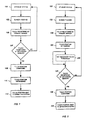
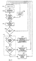
- Fig. 1 is a flow chart illustrating the preferred operation of the present invention.
- the touchscreen is in a pre-touch, stand-by status.
- the screen receives a touch (step 103), for example via a finger, perhaps gloved.
- the primary touch sensor then registers a touch (step 105).
- a secondary sensor Prior to the primary touch sensor determining the coordinates of the touch or sending any information to the operating system ( e . g ., touch position, touch mode, etc .), a secondary sensor confirms that the touch received by the primary sensor is a valid touch (step 107). If the secondary sensor confirms that the touch is valid (step 109), the touch position coordinates are determined (step 111).
- the coordinates of the touch position can be determined by either the primary sensor or the secondary sensor.
- the touch controller then sends the touch information (e . g ., touch position coordinates) to the operating system (step 113). If the secondary sensor does not confirm that a valid touch was received by the primary sensor, no touch information is sent to the operating system and the touch sensor is placed back into stand-by status 101.
- the benefit of this embodiment is that time is not spent on determining invalid touch positions, thus enabling the system to quickly confirm that a valid touch has been received and if the touch is invalidated, to quickly return to stand-by status 101.
- step 105 after the primary sensor registers a touch (step 105), it determines the position of the touch (step 201). After determining touch position, the system can simply query the secondary sensor to determine it has also registered a touch (step 107) and if it has, confirm the touch (step 109) and send the position coordinates to the operating system (step 203). Alternately, after the touch position has been determined (step 201), a coordinate dependent touch threshold is set for the secondary sensor (step 205), thus accounting for coordinate dependent touch sensitivities.
- one of the sensors preferably the secondary sensor, only determines whether or not a touch has been received. Since this sensor does not determine absolute touch position, it can be an inexpensive sensor. Alternately, this sensor can be designed to determine approximate touch position. For example, this sensor can be designed to determine what quadrant of the screen has been touched. In a third alternative this sensor can be designed to determine the actual coordinates of the touch position, thus providing system redundancy.
- one of the sensors is a projective-capacitive sensor and the other is a force sensor.
- the system can be designed such that either of these sensors acts as the primary or touch position coordinate determining sensor while the other sensor acts simply as the validation sensor.
- both sensors accurately determine the touch coordinates thus providing redundancy as well as a more sophisticated method of validating touch.
- one of the sensors can accurately determine the touch coordinates while the second sensor approximates the touch coordinates ( e . g ., to within a touchscreen quadrant).
- Force sensors are typified by temperature compensated strain gauges such as those disclosed in U.S. Patent No. 5,742,222 .
- Force sensors can also be based on peizo systems, such as those disclosed in U.S. Patent Nos. 4,355,202 and 4,675,569 and European Patent Application No. EP 0 754 936 .
- the present invention employs a pressure sensitive force sensor such as that illustrated in UK Patent Application Nos. GB 2 310 288 A , GB 2 321 707 A , and GB 2 326 719 .
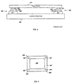
- Fig. 3 based on Fig. 5a of UK Patent Application No. GB 2 321 707 A , illustrates two such force sensors 300.
- piezo-resistive force sensors 300 may be placed between one or more corners of a touch plate 301 and a support structure 303.
- Each force sensor 300 is comprised of a piezo-resistive material 305, the resistance of which changes as it is compressed.
- a top electrode 307 and a bottom electrode 309 permit electronic measurement of the resistance of piezo-resistive material 305.
- a sensor substrate 311 is provided to assure a mechanically robust force sensor construction. Insulating layers (not shown) may be added to provide electrical isolation as needed. In order to easily measure small percentage changes in resistance, the read-out electronics typically places force sensors 300 within a Wheatstone bridge.
- the type of force sensors illustrated in Fig. 3 offer a number of advantages.
- First, the design supports an environmentally rugged construction that is immune to ambient temperature and humidity variations.
- the force sensors can be coupled to the touchscreen in either an overlay or non-overlay configuration and can utilize one or multiple sensors, depending upon whether the force sensor(s) is to supply touch validation or touch coordinates.
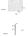
- a single force sensor 401 is located on a touchscreen 405.
- low-stiffness supports at corners 406 and high-stiffness supports at corner 408 may be used to avoid zones of limited or no touch sensitivity.
- sensor 401 is located just outside of the viewing region of screen 405 and underneath a touchscreen cowling 407.
- four force sensors 401-404 may be used, one located at each corner of touchscreen 405 to provide touch coordinates in a manner similar to that disclosed in U.S. Patent No. 5,708,460 .
- a single force sensor 401 typically has a touch sensitivity that is dependent upon the location of the touch position. This sensitivity also depends upon the manner in which touchscreen 405 is mounted ( e . g ., rigid mounts versus soft mounts). Therefore if a single force sensor is to be used to supply touch validation, preferably the touch threshold of the force sensor is set on the basis of the touch position as determined by the projective capacitive sensor described below.
- the other sensor used in the preferred embodiment of the invention is a projective-capacitive sensor.
- Figs. 5 and 6 provide front and cross-sectional views, respectively, of a projective-capacitive touch sensor, such as that disclosed in U.S. Patent No. 5,844,506 , the disclosure of which is incorporated herein for all purposes.
- deposited on substrate 501 is a pattern of electrodes 503, formed using fine wire electrodes, patterned resistive coatings, or other standard electrode designs.
- a protective overlay 601 prevents electrodes 503 from being damaged during use.
- projective-capacitive sensors 503 can be used either to provide the absolute touch position or simply to provide touch confirmation. Typically the spacing of the electrodes is given by the application, i . e ., fine spacing for absolute position and course spacing for simple touch confirmation.
- Projective-capacitive touchscreens such as that shown above and those disclosed in U.S. Patent Nos. 5,650,597 and 4,954,823 and PCT patent applications WO 95/27334 and 96/15464 , the disclosures of which are incorporated herein for all purposes, monitor the change in touchscreen capacitance.
- the capacitance of a projective-capacitive sensor is changed not only by touching the sensor with a grounded object, but also by simply bringing a grounded object into close proximity to the sensor.
- the principal difficulty with this type of touchscreen is due to the various sizes of the grounded objects that can be used with the screen. For example, a small finger ( e .
- a simple signal-level threshold system is not sufficient for determining the actual point of contact with a projective-capacitive sensor since, depending on the threshold, it may indicate a touch prior to the occurrence of the actual touch (e . g ., large user hand with a touchscreen that has been set to recognize a child's fingers) or completely disregard a touch ( e . g ., disregard a child's finger because the screen is set-up for an adult finger).
- touchscreens utilizing force sensors do not have recognition problems with fingers of varying size. Nor do force sensors have difficulty in recognizing gloved hands, styluses, pens, etc . Force sensor touchscreens do, however, suffer from false signals caused by mechanical noise. For example, vibrations to the touchscreen can cause vibrations in the reference mass, thus generating extraneous background signals. Additionally, the extraneous background signals may cause the system to be unable to recognize a valid touch.
- force sensor based touchscreens can experience touch position errors due to the wind. For example, if a wind is blowing parallel to the touchscreen, a person standing in front of the touchscreen will cause an asymmetry in the pressure applied to the left and right-hand portions of the screen. Due to this pressure imbalance, the touchscreen force sensors will erroneously identify the coordinates of a touch. The amount of positional error is subject to the degree of pressure asymmetry applied to the touchscreen by the wind. This asymmetry is dependent upon the wind speed, the angle between the wind and the screen parallel, the degree to which the air flow is modified by the obstacle ( i . e ., the user), the size of the screen, and the amount of force applied by the user's touch.
- force sensors Another problem with force sensors is associated with attempting to achieve a drag and untouch functionality. In order to achieve this functionality, the force sensor signals must be processed well into the sub-Hertz range. Unfortunately some types of force sensors (e . g ., piezoelectric sensors) generate signals that are essentially the time derivatives of the applied force, thus making sub-Hertz information problematic. Even force sensors that generate signals that are proportional to the applied force may have problems processing sub-Hertz information due to mechanical noise.
- force sensors e . g ., piezoelectric sensors
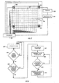
- the primary sensor is a projective-capacitive sensor in which the electrode array is comprised of electrodes 503.
- the projective-capacitive sensor is coupled to a processor 701 that is used to determine the touch position coordinates from the output of the projective-capacitive sensor.
- the secondary touch sensor is a force sensor and, as shown, is comprised of force sensors 401-404. It should be understood that a single force sensor 401 could be used to provide touch validation. Therefore as shown in Fig. 7 , the output of sensor 401 can either be coupled to a monitor 703 and a discriminator 705 to provide touch validation or directly coupled to processor 701 along with the outputs from force sensors 402-404 to provide secondary touch coordinate determination.
- the force sensor is only used to determine when a finger makes contact with the touch surface.
- the system is set-up to require that a certain pressure must be applied to screen 501 in order to register a "touch".
- multiple force sensors e . g ., sensors 401-404
- the sum of the signals from the force sensors must exceed the threshold value. Since in this embodiment the force sensors need not support drag and untouch functionality, the force sensor signals can be processed using a relatively narrow frequency filter. As a result of the narrow frequency filter, mechanical background noise, such as that caused by reference mass vibrations, is relatively easy to suppress.
- Fig. 8 indicates the preferred method for use with the embodiment illustrated in Fig. 7 .
- the system is in a stand-by mode while it awaits a touch (step 801).
- the force sensor(s) detects a touch by determining that the force applied to the touchscreen exceeds a preset threshold (step 803)
- the projective-capacitive system is queried to determine if it also detects a touch (step 805). If the projective-capacitive system does not detect a touch then the system is placed back into stand-by mode (step 801) and the touch is invalidated. If a touch is detected by the projective-capacitive system, then in the preferred embodiment of the invention an untouch threshold is set (step 807).
- This threshold can be, for example, equal to a percentage ( e . g ., 50%) of the projective-capacitive signal amplitude when the touch was first detected by the force sensor.
- a pre-set threshold is used, thus eliminating threshold setting step 807.
- the next step generates the position coordinates of the touch (step 809).
- the position coordinates are determined by the projective-capacitive system.
- the system continues to monitor the projective-capacitive signal, continually generating position coordinates as long as the projective-capacitive signal is above the untouch threshold (step 811). Therefore if the user employs a drag motion (i . e ., dragging a finger across the screen), the system continues to generate the required touch position information. Once the projective-capacitive signal falls below the untouch threshold, the system generates an untouch message and the final position coordinates (step 813) and then returns to the stand-by mode.
- the use of the force sensor eliminates the possibility of the projective-capacitive system responding to a touch prior to actual touch, i . e ., when the user's finger or hand is merely close to the screen but not yet touching the screen.
- employing the threshold setting step discussed above eliminates the problems associated with fingers of varying size or capacitance ( e . g ., small versus large fingers, gloved versus ungloved hands, etc. ) .
- the drag and untouch capability is achieved using the projective-capacitive system, the typical difficulty in processing sub-Hertz information using a force sensor is overcome.
- the problems of false touch generation due to wind or large vibrations as well as the calibration and stability issues surrounding force sensors are avoided since in this embodiment the force sensors are only used to determine touch occurrence, not accurately determine touch position.
- force sensors 401-404 are used to accurately determine position while the projective-capacitive sensors are merely used to confirm that a true touch has occurred.
- the force sensors are set up in a standard configuration in order to achieve the desired accuracy, using techniques well known by those of skill in the art.
- the projective-capacitive sensors are designed to provide minimal accuracy, thus requiring few electrodes 503, possibly as few as a single electrode 503. Preferably more than one electrode is used, thus providing better sensitivity and performance.
- force sensors 401-404 are directly coupled to processor 701 for determining the touch position coordinates while the output of the projective-capacitive sensor is coupled to processor 701 via monitor 703 and discriminator 705.
- Fig. 10 illustrates the method of the invention in which the projective-capacitive sensor is only used as the touch confirmation sensor as discussed above in relation to Fig. 9 .
- the system is in a stand-by mode (step 1001).
- the first step is the detection of a touch by the force sensors (step 1003).
- the projective-capacitive system determines whether or not the touch is a valid touch by determining if the touch is due to a conductive and grounded object (step 1005). If the touch is validated, touch position coordinates are generated by the force sensors (step 1007) and the system is returned to the stand-by mode.
- the system adjusts the threshold of the force sensors (step 1009).
- the required force threshold can be increased, thus avoiding false touches (e . g ., false touches due to wind).
- the force threshold is adjusted to compensate for false touches, periodically the threshold is automatically decreased thus accounting for decreasing noise (e . g ., decreasing wind noise) and providing optimal touch sensitivity.
- the frequency spectrum of the background can also be monitored, thus allowing the use of suitable frequency filters as required.
- the background frequency spectrum can be evaluated and an appropriate frequency filter applied.
- the frequency filter is periodically relaxed or the frequency spectrum is periodically remeasured, thus insuring that unnecessary filtering is not applied.
- both the projective-capacitive and force touch sensor systems are capable of providing touch position coordinates.
- the system touch algorithm is designed to determine which sensor system is likely to provide the most accurate position for the given conditions. The system then obtains touch coordinates from the designated system.
- Fig. 11 illustrates the method used with this dual sensor system.
- the touch system is in a stand-by mode (step 1101).
- the initial touch is detected by the force sensors (step 1103), thus avoiding the proximity errors that can occur with the projective-capacitive sensors.
- the touch algorithm adjusts the threshold of the projective-capacitive sensors in order to overcome differences in finger size or conductivity (step 1107). Since both sensors provide full positional accuracy, the next step is to determine the offset between the two touch positions registered by the two sensors (step 1109). If the offset is greater than is reasonable ( i . e ., greater than can be accounted for due to wind, hand size, etc .), the system invalidates the touch and returns to stand-by mode. If the offset between the two touch positions is within acceptable limits, the touch is verified and the process continues.
- the touch algorithm next determines which touch sensor to use in determining touch coordinates (step 1111). For example, the touch algorithm can recognize that the system is being used in a drag mode by determining that the touch position is changing prior to an untouch message being sent (step 1113). In this instance preferably the projective-capacitive system is used to determine both touch position and the location at which untouch occurs (step 1115) since this system is generally better suited for supporting the drag mode as noted above. Alternately, if the system determines that the vibrational or wind generated background noise is too great (step 1117) the touch algorithm can select the projective-capacitive system to provide touch positions (step 1119). Otherwise the force sensors can be used to determine touch position (step 1121).
- the system can adjust the force sensor thresholds (step 1123) prior to returning the system to the stand-by mode.
- the amplitude threshold or the frequency filter for the force sensors can be adjusted.
- the combination of sensors described above has other advantages. For example, in the system stand-by mode, only one of the sensor systems needs to be in the ready state. Thus the other sensor system can be in a completely unpowered state, thereby reducing power consumption. For example, the force sensors can remain in the alert state and, once triggered, the projective-capacitive electrodes can be scanned.
- Another advantage of the above combined sensors is the possibility of obtaining limited user identification.
- a right-handed user due to the capacitance of the user's hand, tends to project a touch position with the projective-capacitive system that is to the right of the point of contact as determined by the force sensors.
- a left-handed user tends to project a touch position that is to the left of the point of contact as determined by the force sensors.
- Other touch attributes that can be used in an identification system are offset between the touch positions determined by the two systems, the force used to touch the screen, the speed at which the user touches multiple areas on the screen, and the time between a user's initial touch and their untouch.
- the system can be designed to monitor only certain touch strokes (e . g ., user code for an ATM machine), or all touch strokes.
- One potential use of the data is to provide different users with different menus, touchscreens, etc. based on past use.
- a typical touchscreen controller requires a microprocessor, RAM, ROM, an analog-to-digital converter (ADC), power supply circuitry, digital circuits to support communication with the host computer, and a printed circuit board.
- ADC analog-to-digital converter
- controller electronics may be common to two different types of sensors.
- some types of piezoresistive force sensors can be read out with an alternating-current excitation voltage in the tens of kiloHertz range as opposed to the more typical approach of using a direct-current excitation voltage. Therefore the same excitation frequency and similar receive electronics can be used for both the force sensors and the projective-capacitive sense electrodes.
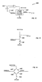
- Fig. 12 is an illustration of a generic block circuit diagram for a sensor element readout circuit 1200. Negative feedback assures that the voltage on a feedback line 1201 is the same as the oscillating voltage V 0 produced by a reference 1203. The output from a sensor element 1205 is the signal voltage ⁇ V superposed on the reference voltage V 0 . The output line plus a reference voltage line provide a differential signal output voltage ⁇ V.
- Fig. 13 illustrates a projective-capacitive sensor element for use with the circuit of Fig. 12 .
- a variable capacitor 1301 represents the projective-capacitive sensor electrode.
- a resistor 1303 supports the readout scheme. Resistor 1303 can either be built directly into the sensor or located with the readout electrodes.
- the feedback circuit illustrated in Fig. 12 can also be used with the alternating current readout of a force sensor.
- Some force sensors for example those manufactured by C-Cubed Limited, are read out via a Wheatstone bridge.
- one or more of the four resistors 1401-1404 may correspond to piezoresistive elements in the force sensor.
- the bridge is connected to ground via a capacitor 1405.
- capacitor 1405 is not required, it may useful for reducing the differences between the excitation and feedback voltages, thereby making the ratio of ⁇ V to V 0 more similar to signals from the projective-capacitive electrodes.
Landscapes
- Engineering & Computer Science (AREA)
- General Engineering & Computer Science (AREA)
- Theoretical Computer Science (AREA)
- Human Computer Interaction (AREA)
- Physics & Mathematics (AREA)
- General Physics & Mathematics (AREA)
- Position Input By Displaying (AREA)
- Force Measurement Appropriate To Specific Purposes (AREA)
Priority Applications (2)
| Application Number | Priority Date | Filing Date | Title |
|---|---|---|---|
| EP10182361A EP2261780B1 (de) | 2000-10-27 | 2000-10-27 | Berührungsempfindlicher Bildschirm mit projektiven kapazitiven Sensoren und Kraftsensoren |
| EP10182573A EP2261781B1 (de) | 2000-10-27 | 2000-10-27 | Berührungsempfindlicher Bildschirm mit projektiven kapazitiven Sensoren und Kraftsensoren |
Applications Claiming Priority (2)
| Application Number | Priority Date | Filing Date | Title |
|---|---|---|---|
| PCT/US2000/029602 WO2002035461A1 (en) | 2000-10-27 | 2000-10-27 | Dual sensor touchscreen utilizing projective-capacitive and force touch sensors |
| EP00973925A EP1330779B1 (de) | 2000-10-27 | 2000-10-27 | Berührungsempfindlicher bildschirm mit projektiven kapazitiven sensoren und kraftsensoren |
Related Parent Applications (2)
| Application Number | Title | Priority Date | Filing Date |
|---|---|---|---|
| EP00973925.1 Division | 2000-10-27 | ||
| EP00973925A Division EP1330779B1 (de) | 2000-10-27 | 2000-10-27 | Berührungsempfindlicher bildschirm mit projektiven kapazitiven sensoren und kraftsensoren |
Related Child Applications (3)
| Application Number | Title | Priority Date | Filing Date |
|---|---|---|---|
| EP10182573A Division EP2261781B1 (de) | 2000-10-27 | 2000-10-27 | Berührungsempfindlicher Bildschirm mit projektiven kapazitiven Sensoren und Kraftsensoren |
| EP10182361.5 Division-Into | 2010-09-29 | ||
| EP10182573.5 Division-Into | 2010-09-29 |
Publications (3)
| Publication Number | Publication Date |
|---|---|
| EP2133777A2 true EP2133777A2 (de) | 2009-12-16 |
| EP2133777A3 EP2133777A3 (de) | 2010-03-31 |
| EP2133777B1 EP2133777B1 (de) | 2011-10-12 |
Family
ID=21741929
Family Applications (4)
| Application Number | Title | Priority Date | Filing Date |
|---|---|---|---|
| EP10182361A Expired - Lifetime EP2261780B1 (de) | 2000-10-27 | 2000-10-27 | Berührungsempfindlicher Bildschirm mit projektiven kapazitiven Sensoren und Kraftsensoren |
| EP00973925A Expired - Lifetime EP1330779B1 (de) | 2000-10-27 | 2000-10-27 | Berührungsempfindlicher bildschirm mit projektiven kapazitiven sensoren und kraftsensoren |
| EP10182573A Expired - Lifetime EP2261781B1 (de) | 2000-10-27 | 2000-10-27 | Berührungsempfindlicher Bildschirm mit projektiven kapazitiven Sensoren und Kraftsensoren |
| EP09171892A Expired - Lifetime EP2133777B1 (de) | 2000-10-27 | 2000-10-27 | Berührungsempfindlicher Bildschirm mit projektiven kapazitiven Sensoren und Kraftsensoren |
Family Applications Before (3)
| Application Number | Title | Priority Date | Filing Date |
|---|---|---|---|
| EP10182361A Expired - Lifetime EP2261780B1 (de) | 2000-10-27 | 2000-10-27 | Berührungsempfindlicher Bildschirm mit projektiven kapazitiven Sensoren und Kraftsensoren |
| EP00973925A Expired - Lifetime EP1330779B1 (de) | 2000-10-27 | 2000-10-27 | Berührungsempfindlicher bildschirm mit projektiven kapazitiven sensoren und kraftsensoren |
| EP10182573A Expired - Lifetime EP2261781B1 (de) | 2000-10-27 | 2000-10-27 | Berührungsempfindlicher Bildschirm mit projektiven kapazitiven Sensoren und Kraftsensoren |
Country Status (5)
| Country | Link |
|---|---|
| EP (4) | EP2261780B1 (de) |
| JP (1) | JP4629306B2 (de) |
| AU (1) | AU2001212370A1 (de) |
| DE (1) | DE60043457D1 (de) |
| WO (1) | WO2002035461A1 (de) |
Cited By (14)
| Publication number | Priority date | Publication date | Assignee | Title |
|---|---|---|---|---|
| EP2657812A4 (de) * | 2010-12-24 | 2015-06-17 | Graphene Square Inc | Berührungssensor mit graphin zum gleichzeitigen erfassung von druck und position |
| US9223297B2 (en) | 2013-02-28 | 2015-12-29 | The Nielsen Company (Us), Llc | Systems and methods for identifying a user of an electronic device |
| WO2013082276A3 (en) * | 2011-11-30 | 2016-04-07 | Arbitron, Inc. | Tactile and gestational identification and linking to media consumption |
| US9485534B2 (en) | 2012-04-16 | 2016-11-01 | The Nielsen Company (Us), Llc | Methods and apparatus to detect user attentiveness to handheld computing devices |
| US9519909B2 (en) | 2012-03-01 | 2016-12-13 | The Nielsen Company (Us), Llc | Methods and apparatus to identify users of handheld computing devices |
| US9641172B2 (en) | 2012-06-27 | 2017-05-02 | Ford Global Technologies, Llc | Proximity switch assembly having varying size electrode fingers |
| US9654103B2 (en) | 2015-03-18 | 2017-05-16 | Ford Global Technologies, Llc | Proximity switch assembly having haptic feedback and method |
| US9660644B2 (en) | 2012-04-11 | 2017-05-23 | Ford Global Technologies, Llc | Proximity switch assembly and activation method |
| US9692411B2 (en) | 2011-05-13 | 2017-06-27 | Flow Control LLC | Integrated level sensing printed circuit board |
| US9831870B2 (en) | 2012-04-11 | 2017-11-28 | Ford Global Technologies, Llc | Proximity switch assembly and method of tuning same |
| US9904416B2 (en) | 2012-07-17 | 2018-02-27 | Nókia Technologies Oy | Apparatus, method and computer program for enabling user input |
| US9944237B2 (en) | 2012-04-11 | 2018-04-17 | Ford Global Technologies, Llc | Proximity switch assembly with signal drift rejection and method |
| US10501027B2 (en) | 2011-11-03 | 2019-12-10 | Ford Global Technologies, Llc | Proximity switch having wrong touch adaptive learning and method |
| US10595574B2 (en) | 2011-08-08 | 2020-03-24 | Ford Global Technologies, Llc | Method of interacting with proximity sensor with a glove |
Families Citing this family (128)
| Publication number | Priority date | Publication date | Assignee | Title |
|---|---|---|---|---|
| US7808479B1 (en) | 2003-09-02 | 2010-10-05 | Apple Inc. | Ambidextrous mouse |
| US7663607B2 (en) | 2004-05-06 | 2010-02-16 | Apple Inc. | Multipoint touchscreen |
| US7532202B2 (en) | 2002-05-08 | 2009-05-12 | 3M Innovative Properties Company | Baselining techniques in force-based touch panel systems |
| US11275405B2 (en) | 2005-03-04 | 2022-03-15 | Apple Inc. | Multi-functional hand-held device |
| US7656393B2 (en) | 2005-03-04 | 2010-02-02 | Apple Inc. | Electronic device having display and surrounding touch sensitive bezel for user interface and control |
| US7538759B2 (en) | 2004-05-07 | 2009-05-26 | Next Holdings Limited | Touch panel display system with illumination and detection provided from a single edge |
| GB0412787D0 (en) * | 2004-06-09 | 2004-07-14 | Koninkl Philips Electronics Nv | Input system |
| KR101018751B1 (ko) * | 2004-09-24 | 2011-03-04 | 삼성전자주식회사 | 표시 장치 및 그 구동 방법 |
| KR102305019B1 (ko) * | 2005-03-04 | 2021-09-27 | 애플 인크. | 다기능 휴대용 장치 |
| US9182837B2 (en) | 2005-11-28 | 2015-11-10 | Synaptics Incorporated | Methods and systems for implementing modal changes in a device in response to proximity and force indications |
| US8018440B2 (en) | 2005-12-30 | 2011-09-13 | Microsoft Corporation | Unintentional touch rejection |
| DE102006000637A1 (de) * | 2006-01-03 | 2007-07-05 | Robert Bosch Gmbh | Anzeigevorrichtung mit Berührung sensitiver Oberfläche |
| KR20110059776A (ko) | 2006-06-09 | 2011-06-03 | 애플 인크. | 터치 스크린 액정 디스플레이 |
| US9710095B2 (en) | 2007-01-05 | 2017-07-18 | Apple Inc. | Touch screen stack-ups |
| JP5010451B2 (ja) * | 2007-09-11 | 2012-08-29 | アルプス電気株式会社 | 入力装置 |
| TWI358029B (en) * | 2008-05-16 | 2012-02-11 | Htc Corp | Method for filtering out signals from touch device |
| CN102047209B (zh) * | 2008-06-10 | 2013-12-11 | 诺基亚公司 | 触摸按钮错误激活抑制 |
| US9477342B2 (en) * | 2008-08-26 | 2016-10-25 | Google Technology Holdings LLC | Multi-touch force sensing touch-screen devices and methods |
| US20100123686A1 (en) * | 2008-11-19 | 2010-05-20 | Sony Ericsson Mobile Communications Ab | Piezoresistive force sensor integrated in a display |
| KR101637879B1 (ko) * | 2009-02-06 | 2016-07-08 | 엘지전자 주식회사 | 휴대 단말기 및 그 동작방법 |
| JP5493739B2 (ja) | 2009-03-19 | 2014-05-14 | ソニー株式会社 | センサ装置及び情報処理装置 |
| EP2241955A1 (de) * | 2009-04-16 | 2010-10-20 | CN Innovations limited | Elektronische Berührungsbildschirmvorrichtung |
| EP2282256A1 (de) * | 2009-08-04 | 2011-02-09 | Deutsche Telekom AG | Elektronische Vorrichtung und Verfahren zum Steuern einer elektronischen Vorrichtung |
| US9430078B2 (en) | 2009-08-12 | 2016-08-30 | Google Technology Holdings LLC | Printed force sensor within a touch screen |
| EP2306269A1 (de) * | 2009-10-02 | 2011-04-06 | Research In Motion Limited | Verfahren zum Schalten zwischen Betriebsmodi und eine zur Durchführung des Verfahrens konfigurierte tragbare elektronische Vorrichtung |
| EP2320307A1 (de) | 2009-10-13 | 2011-05-11 | Research In Motion Limited | Tragbare elektronische Vorrichtung mit berührungsempfindlicher Anzeige und Verfahren zu deren Steuerung |
| EP2320309B1 (de) | 2009-10-13 | 2014-02-12 | BlackBerry Limited | Tragbare elektronische Vorrichtung mit berührungsempfindlicher Anzeige und Verfahren zu deren Steuerung |
| EP2320308B1 (de) | 2009-10-13 | 2017-05-10 | BlackBerry Limited | Tragbare elektronische Vorrichtung mit berührungsempfindlicher Anzeige und Verfahren zu deren Steuerung |
| US9383847B2 (en) | 2009-10-13 | 2016-07-05 | Blackberry Limited | Portable electronic device including touch-sensitive display and method of controlling same |
| JP5529515B2 (ja) * | 2009-12-14 | 2014-06-25 | 京セラ株式会社 | 触感呈示装置 |
| EP2335578A1 (de) * | 2009-12-21 | 2011-06-22 | Koninklijke Philips Electronics N.V. | Sensorensystem |
| JP5526761B2 (ja) * | 2009-12-22 | 2014-06-18 | ソニー株式会社 | センサ装置及び情報処理装置 |
| JP2011154564A (ja) * | 2010-01-27 | 2011-08-11 | Minebea Co Ltd | 電子機器用の入力装置、入力制御方法、及び電子機器。 |
| JP2011154563A (ja) * | 2010-01-27 | 2011-08-11 | Minebea Co Ltd | キーボード装置及びこれを用いた電子機器 |
| JP5382354B2 (ja) * | 2010-01-28 | 2014-01-08 | ミネベア株式会社 | 電子機器用の入力装置、入力制御方法、及び電子機器。 |
| WO2011111302A1 (ja) | 2010-03-10 | 2011-09-15 | パナソニック株式会社 | 押し込み位置制御装置、押し込み位置制御方法及びタッチセンサシステム |
| US9436219B2 (en) | 2010-05-12 | 2016-09-06 | Litl Llc | Remote control to operate computer system |
| US8938753B2 (en) | 2010-05-12 | 2015-01-20 | Litl Llc | Configurable computer system |
| WO2011156447A1 (en) | 2010-06-11 | 2011-12-15 | 3M Innovative Properties Company | Positional touch sensor with force measurement |
| KR101288740B1 (ko) | 2010-07-01 | 2013-07-23 | 주식회사 팬택 | 노이즈 인식하는 터치 스크린 장치 및 이를 이용한 터치 스크린 장치의 제어 방법 |
| US8804056B2 (en) | 2010-12-22 | 2014-08-12 | Apple Inc. | Integrated touch screens |
| JP2012173958A (ja) * | 2011-02-21 | 2012-09-10 | Mitsubishi Electric Corp | タッチパネル付き表示装置 |
| TWI550445B (zh) * | 2011-03-17 | 2016-09-21 | Kyocera Corp | 觸感顯示裝置 |
| JP5831542B2 (ja) * | 2011-04-08 | 2015-12-09 | 株式会社村田製作所 | 変位センサ、変位検出装置 |
| EP2708985A4 (de) | 2011-05-12 | 2014-11-26 | Alps Electric Co Ltd | Eingabevorrichtung und mehrpunktlasterkennungsverfahren unter verwendung der eingabevorrichtung |
| US8975903B2 (en) | 2011-06-09 | 2015-03-10 | Ford Global Technologies, Llc | Proximity switch having learned sensitivity and method therefor |
| US8928336B2 (en) | 2011-06-09 | 2015-01-06 | Ford Global Technologies, Llc | Proximity switch having sensitivity control and method therefor |
| JP5329681B2 (ja) | 2012-01-06 | 2013-10-30 | シャープ株式会社 | タッチパネルシステムおよび電子機器 |
| WO2012176639A1 (en) | 2011-06-22 | 2012-12-27 | Sharp Kabushiki Kaisha | Touch panel system and electronic device |
| WO2013001920A1 (en) | 2011-06-29 | 2013-01-03 | Sharp Kabushiki Kaisha | Touch sensor system and electronic device |
| US9143126B2 (en) | 2011-09-22 | 2015-09-22 | Ford Global Technologies, Llc | Proximity switch having lockout control for controlling movable panel |
| US8994228B2 (en) | 2011-11-03 | 2015-03-31 | Ford Global Technologies, Llc | Proximity switch having wrong touch feedback |
| US8878438B2 (en) | 2011-11-04 | 2014-11-04 | Ford Global Technologies, Llc | Lamp and proximity switch assembly and method |
| DE102011119746A1 (de) | 2011-11-30 | 2013-06-06 | Audi Ag | Betätigungsvorrichtung mit einer manuell zu bedienenden berührungssensitiven Oberfläche |
| CN103186334B (zh) * | 2011-12-28 | 2016-08-24 | 宇龙计算机通信科技(深圳)有限公司 | 一种终端的控制方法及装置 |
| CN104335146B (zh) | 2012-02-02 | 2017-06-30 | 索尼移动通讯有限公司 | 便携式电子装置以及控制具有接近感测用户接口的便携式电子装置的方法 |
| JP5865724B2 (ja) * | 2012-02-16 | 2016-02-17 | アルプス電気株式会社 | 入力装置及び前記入力装置を用いた重心位置の補正方法 |
| WO2013135252A1 (en) * | 2012-03-15 | 2013-09-19 | Sony Mobile Communications Ab | Method for controlling a touch sensor |
| US9219472B2 (en) | 2012-04-11 | 2015-12-22 | Ford Global Technologies, Llc | Proximity switch assembly and activation method using rate monitoring |
| US9520875B2 (en) | 2012-04-11 | 2016-12-13 | Ford Global Technologies, Llc | Pliable proximity switch assembly and activation method |
| US9197206B2 (en) | 2012-04-11 | 2015-11-24 | Ford Global Technologies, Llc | Proximity switch having differential contact surface |
| US8933708B2 (en) | 2012-04-11 | 2015-01-13 | Ford Global Technologies, Llc | Proximity switch assembly and activation method with exploration mode |
| US9531379B2 (en) | 2012-04-11 | 2016-12-27 | Ford Global Technologies, Llc | Proximity switch assembly having groove between adjacent proximity sensors |
| US9287864B2 (en) | 2012-04-11 | 2016-03-15 | Ford Global Technologies, Llc | Proximity switch assembly and calibration method therefor |
| US9184745B2 (en) | 2012-04-11 | 2015-11-10 | Ford Global Technologies, Llc | Proximity switch assembly and method of sensing user input based on signal rate of change |
| US9568527B2 (en) | 2012-04-11 | 2017-02-14 | Ford Global Technologies, Llc | Proximity switch assembly and activation method having virtual button mode |
| US9559688B2 (en) | 2012-04-11 | 2017-01-31 | Ford Global Technologies, Llc | Proximity switch assembly having pliable surface and depression |
| US9065447B2 (en) | 2012-04-11 | 2015-06-23 | Ford Global Technologies, Llc | Proximity switch assembly and method having adaptive time delay |
| WO2013165601A1 (en) | 2012-05-03 | 2013-11-07 | Yknots Industries Llc | Moment compensated bending beam sensor for load measurement on platform supported by bending beams |
| US9136840B2 (en) | 2012-05-17 | 2015-09-15 | Ford Global Technologies, Llc | Proximity switch assembly having dynamic tuned threshold |
| US8981602B2 (en) | 2012-05-29 | 2015-03-17 | Ford Global Technologies, Llc | Proximity switch assembly having non-switch contact and method |
| US10251316B1 (en) | 2012-05-29 | 2019-04-02 | Mistbox, Inc. | Air conditioner mister, apparatus and method |
| US9198980B1 (en) * | 2012-05-29 | 2015-12-01 | Environmyst LLC | Air conditioner mister, apparatus and method |
| US9337832B2 (en) | 2012-06-06 | 2016-05-10 | Ford Global Technologies, Llc | Proximity switch and method of adjusting sensitivity therefor |
| US9678605B2 (en) | 2012-06-28 | 2017-06-13 | Synaptics Incorporated | Systems and methods for switching sensing regimes for gloved and ungloved user input |
| IL221862A (en) * | 2012-09-10 | 2015-03-31 | Elbit Systems Ltd | Attacking a physical touch event on optical touch screens |
| US8922340B2 (en) | 2012-09-11 | 2014-12-30 | Ford Global Technologies, Llc | Proximity switch based door latch release |
| US9557846B2 (en) * | 2012-10-04 | 2017-01-31 | Corning Incorporated | Pressure-sensing touch system utilizing optical and capacitive systems |
| US8796575B2 (en) | 2012-10-31 | 2014-08-05 | Ford Global Technologies, Llc | Proximity switch assembly having ground layer |
| US9582122B2 (en) | 2012-11-12 | 2017-02-28 | Microsoft Technology Licensing, Llc | Touch-sensitive bezel techniques |
| US9983715B2 (en) | 2012-12-17 | 2018-05-29 | Apple Inc. | Force detection in touch devices using piezoelectric sensors |
| EP2770638A1 (de) | 2013-02-20 | 2014-08-27 | Aito Interactive Oy | Piezoelektrischer Sensor und ein elektrisches Gerät, eine Installation oder eine Vorrichtung mit mindestens einem piezoelektrischen Sensor |
| US9311204B2 (en) | 2013-03-13 | 2016-04-12 | Ford Global Technologies, Llc | Proximity interface development system having replicator and method |
| WO2014149023A1 (en) | 2013-03-15 | 2014-09-25 | Rinand Solutions Llc | Force sensing of inputs through strain analysis |
| JP5487350B1 (ja) * | 2013-05-31 | 2014-05-07 | 富士ソフト株式会社 | タッチ入力装置、入力検出方法、およびコンピュータプログラム |
| EP2821897B1 (de) * | 2013-07-04 | 2019-08-21 | Sony Corporation | Fingererkennung auf Berührungsschirmen für mobile Vorrichtungen |
| EP2827227A1 (de) | 2013-07-16 | 2015-01-21 | Honeywell Romania S.R.L. | Berührungssensor und Verfahren zur Herstellung davon |
| CN110134283B (zh) | 2013-10-28 | 2022-10-11 | 苹果公司 | 基于压电的力感测 |
| JP5905434B2 (ja) * | 2013-11-07 | 2016-04-20 | 株式会社東海理化電機製作所 | 操作装置 |
| AU2015100011B4 (en) | 2014-01-13 | 2015-07-16 | Apple Inc. | Temperature compensating transparent force sensor |
| US9477337B2 (en) | 2014-03-14 | 2016-10-25 | Microsoft Technology Licensing, Llc | Conductive trace routing for display and bezel sensors |
| JP5656307B1 (ja) | 2014-06-20 | 2015-01-21 | パナソニック株式会社 | 電子機器 |
| JP5736551B1 (ja) | 2014-06-20 | 2015-06-17 | パナソニックIpマネジメント株式会社 | 電子機器及び制御方法 |
| JP5866526B2 (ja) | 2014-06-20 | 2016-02-17 | パナソニックIpマネジメント株式会社 | 電子機器、制御方法、及びプログラム |
| GB2531369A (en) | 2014-06-20 | 2016-04-20 | Panasonic Ip Man Co Ltd | Electronic apparatus |
| US9851845B2 (en) | 2014-08-12 | 2017-12-26 | Apple Inc. | Temperature compensation for transparent force sensors |
| KR102240828B1 (ko) | 2014-08-28 | 2021-04-15 | 엘지디스플레이 주식회사 | 터치 패널 및 이의 구동 장치 |
| JP6244034B2 (ja) * | 2014-09-03 | 2017-12-06 | アルプス電気株式会社 | 入力装置 |
| US9983745B2 (en) | 2014-09-19 | 2018-05-29 | Kabushiki Kaisha Tokai Rika Denki Seisakusho | Touch sensor device and controller |
| US10275092B2 (en) | 2014-09-24 | 2019-04-30 | Hewlett-Packard Development Company, L.P. | Transforming received touch input |
| US10038443B2 (en) | 2014-10-20 | 2018-07-31 | Ford Global Technologies, Llc | Directional proximity switch assembly |
| FR3028966B1 (fr) * | 2014-11-26 | 2018-01-26 | Sequeris | Dispositif et procede de commande et appareil comportant un tel dispositif |
| DE102014019128A1 (de) | 2014-12-19 | 2016-06-23 | Audi Ag | Bedieneinrichtung für ein Kraftfahrzeug, Kraftfahrzeug und Verfahren zum Betreiben einer Bedieneinrichtung |
| US9436338B2 (en) * | 2014-12-22 | 2016-09-06 | Microsoft Technology Licensing, Llc | Active matrix capacitive touch sensor |
| JP6038202B2 (ja) * | 2015-02-06 | 2016-12-07 | 京セラドキュメントソリューションズ株式会社 | 入力装置および電子機器 |
| US9548733B2 (en) | 2015-05-20 | 2017-01-17 | Ford Global Technologies, Llc | Proximity sensor assembly having interleaved electrode configuration |
| US9612170B2 (en) | 2015-07-21 | 2017-04-04 | Apple Inc. | Transparent strain sensors in an electronic device |
| US10055048B2 (en) | 2015-07-31 | 2018-08-21 | Apple Inc. | Noise adaptive force touch |
| US9874965B2 (en) | 2015-09-11 | 2018-01-23 | Apple Inc. | Transparent strain sensors in an electronic device |
| US9886118B2 (en) | 2015-09-30 | 2018-02-06 | Apple Inc. | Transparent force sensitive structures in an electronic device |
| CN105607773B (zh) | 2015-12-24 | 2019-04-16 | 上海天马微电子有限公司 | 一种触摸屏 |
| CN105607790B (zh) * | 2016-02-02 | 2018-10-19 | 上海交通大学 | 一种电阻电容混合式压力传感器及其使用方法 |
| US10006820B2 (en) | 2016-03-08 | 2018-06-26 | Apple Inc. | Magnetic interference avoidance in resistive sensors |
| US10209830B2 (en) | 2016-03-31 | 2019-02-19 | Apple Inc. | Electronic device having direction-dependent strain elements |
| US10452211B2 (en) | 2016-05-27 | 2019-10-22 | Synaptics Incorporated | Force sensor with uniform response in an axis |
| JP6608535B2 (ja) * | 2016-08-05 | 2019-11-20 | アルプスアルパイン株式会社 | 入力装置、荷重算出方法、及び荷重算出プログラム |
| US10133418B2 (en) | 2016-09-07 | 2018-11-20 | Apple Inc. | Force sensing in an electronic device using a single layer of strain-sensitive structures |
| US10444887B2 (en) * | 2016-09-20 | 2019-10-15 | Cypress Semiconductor Corporation | Force sensing |
| DE102016123559A1 (de) | 2016-12-06 | 2018-06-07 | Dr. Ing. H.C. F. Porsche Aktiengesellschaft | Bedienelement mit einstellbarer Kraftschwelle |
| US10444091B2 (en) | 2017-04-11 | 2019-10-15 | Apple Inc. | Row column architecture for strain sensing |
| KR102390475B1 (ko) * | 2017-04-26 | 2022-04-26 | 엘지디스플레이 주식회사 | 센서를 갖는 전자장치와 이의 구동 방법 |
| JP6474853B2 (ja) * | 2017-04-27 | 2019-02-27 | レノボ・シンガポール・プライベート・リミテッド | 入出力装置、制御方法および電子機器 |
| CN107102773A (zh) * | 2017-04-27 | 2017-08-29 | 努比亚技术有限公司 | 一种防误触控方法、终端及计算机可读存储介质 |
| US10309846B2 (en) | 2017-07-24 | 2019-06-04 | Apple Inc. | Magnetic field cancellation for strain sensors |
| DE102018001200B3 (de) * | 2018-02-14 | 2019-04-25 | Daimler Ag | Verfahren und Vorrichtung zur Bestimmung einer Nutzereingabe |
| US10782818B2 (en) | 2018-08-29 | 2020-09-22 | Apple Inc. | Load cell array for detection of force input to an electronic device enclosure |
| US11774940B2 (en) | 2021-03-29 | 2023-10-03 | Rockwell Automation Technologies, Inc. | Redundant touchless inputs for automation system |
| AU2022296590A1 (en) | 2021-06-24 | 2024-01-04 | Icu Medical, Inc. | Infusion pump touchscreen with false touch rejection |
Citations (18)
| Publication number | Priority date | Publication date | Assignee | Title |
|---|---|---|---|---|
| US4355202A (en) | 1980-12-08 | 1982-10-19 | Bell Telephone Laboratories, Incorporated | Mounting arrangement for a position locating system |
| US4675569A (en) | 1986-08-04 | 1987-06-23 | International Business Machines Corporation | Touch screen mounting assembly |
| US4954823A (en) | 1984-04-17 | 1990-09-04 | Binstead Ronald P | Touch keyboard systems |
| US5231381A (en) | 1989-10-02 | 1993-07-27 | U.S. Philips Corp. | Data processing system with a touch screen and a digitizing tablet, both integrated in an input device |
| WO1995027334A1 (en) | 1994-04-05 | 1995-10-12 | Ronald Peter Binstead | Multiple input proximity detector and touchpad system |
| US5510813A (en) | 1993-08-26 | 1996-04-23 | U.S. Philips Corporation | Data processing device comprising a touch screen and a force sensor |
| WO1996015464A1 (en) | 1994-11-14 | 1996-05-23 | Moonstone Technology Limited | Capacitive touch detectors |
| US5543589A (en) | 1994-05-23 | 1996-08-06 | International Business Machines Corporation | Touchpad with dual sensor that simplifies scanning |
| EP0754936A2 (de) | 1995-07-21 | 1997-01-22 | Carmen Diessner | Kraftmesseinrichtung |
| US5650597A (en) | 1995-01-20 | 1997-07-22 | Dynapro Systems, Inc. | Capacitive touch sensor |
| GB2310288A (en) | 1996-02-17 | 1997-08-20 | John Karl Atkinson | A force sensitive device |
| US5670755A (en) | 1994-04-21 | 1997-09-23 | Samsung Display Devices Co., Ltd. | Information input apparatus having functions of both touch panel and digitizer, and driving method thereof |
| US5708460A (en) | 1995-06-02 | 1998-01-13 | Avi Systems, Inc. | Touch screen |
| US5742222A (en) | 1995-05-26 | 1998-04-21 | Avi Systems, Inc. | Direct adhering polysilicon based strain gage |
| US5777607A (en) | 1995-02-22 | 1998-07-07 | U.S. Philips Corporation | Low-cost resistive tablet with touch and stylus functionality |
| GB2321707A (en) | 1997-01-31 | 1998-08-05 | John Karl Atkinson | A means for determining the x, y and z co-ordinates of a touched surface |
| US5801682A (en) | 1995-03-24 | 1998-09-01 | Sextant Avionique | Tactile designation device with high-resolution transparent capacitive surface |
| GB2326719A (en) | 1997-06-19 | 1998-12-30 | John Karl Atkinson | Force sensitive devices |
Family Cites Families (7)
| Publication number | Priority date | Publication date | Assignee | Title |
|---|---|---|---|---|
| JPH0511916A (ja) * | 1991-07-02 | 1993-01-22 | Seiko Instr Inc | ワイヤレス座標読取装置 |
| JP3126816B2 (ja) * | 1992-07-16 | 2001-01-22 | 株式会社ワコム | 手書文字入力方法及びそれを使用したペン入力コンピュータ |
| JPH06332607A (ja) * | 1993-05-19 | 1994-12-02 | Mitsubishi Electric Corp | 表示一体型入力装置 |
| JPH09269861A (ja) * | 1996-01-30 | 1997-10-14 | Seiko Epson Corp | タブレット装置及びタブレット装置の検出方法、および電子機器 |
| US6054979A (en) * | 1996-08-21 | 2000-04-25 | Compaq Computer Corporation | Current sensing touchpad for computers and the like |
| JPH1069346A (ja) * | 1996-08-28 | 1998-03-10 | Alps Electric Co Ltd | 座標入力装置およびその制御方法 |
| JP3624070B2 (ja) * | 1997-03-07 | 2005-02-23 | キヤノン株式会社 | 座標入力装置及びその制御方法 |
-
2000
- 2000-10-27 DE DE60043457T patent/DE60043457D1/de not_active Expired - Lifetime
- 2000-10-27 EP EP10182361A patent/EP2261780B1/de not_active Expired - Lifetime
- 2000-10-27 EP EP00973925A patent/EP1330779B1/de not_active Expired - Lifetime
- 2000-10-27 AU AU2001212370A patent/AU2001212370A1/en not_active Abandoned
- 2000-10-27 EP EP10182573A patent/EP2261781B1/de not_active Expired - Lifetime
- 2000-10-27 JP JP2002538371A patent/JP4629306B2/ja not_active Expired - Lifetime
- 2000-10-27 EP EP09171892A patent/EP2133777B1/de not_active Expired - Lifetime
- 2000-10-27 WO PCT/US2000/029602 patent/WO2002035461A1/en not_active Ceased
Patent Citations (19)
| Publication number | Priority date | Publication date | Assignee | Title |
|---|---|---|---|---|
| US4355202A (en) | 1980-12-08 | 1982-10-19 | Bell Telephone Laboratories, Incorporated | Mounting arrangement for a position locating system |
| US4954823A (en) | 1984-04-17 | 1990-09-04 | Binstead Ronald P | Touch keyboard systems |
| US4675569A (en) | 1986-08-04 | 1987-06-23 | International Business Machines Corporation | Touch screen mounting assembly |
| US5231381A (en) | 1989-10-02 | 1993-07-27 | U.S. Philips Corp. | Data processing system with a touch screen and a digitizing tablet, both integrated in an input device |
| US5510813A (en) | 1993-08-26 | 1996-04-23 | U.S. Philips Corporation | Data processing device comprising a touch screen and a force sensor |
| WO1995027334A1 (en) | 1994-04-05 | 1995-10-12 | Ronald Peter Binstead | Multiple input proximity detector and touchpad system |
| US5844506A (en) | 1994-04-05 | 1998-12-01 | Binstead; Ronald Peter | Multiple input proximity detector and touchpad system |
| US5670755A (en) | 1994-04-21 | 1997-09-23 | Samsung Display Devices Co., Ltd. | Information input apparatus having functions of both touch panel and digitizer, and driving method thereof |
| US5543589A (en) | 1994-05-23 | 1996-08-06 | International Business Machines Corporation | Touchpad with dual sensor that simplifies scanning |
| WO1996015464A1 (en) | 1994-11-14 | 1996-05-23 | Moonstone Technology Limited | Capacitive touch detectors |
| US5650597A (en) | 1995-01-20 | 1997-07-22 | Dynapro Systems, Inc. | Capacitive touch sensor |
| US5777607A (en) | 1995-02-22 | 1998-07-07 | U.S. Philips Corporation | Low-cost resistive tablet with touch and stylus functionality |
| US5801682A (en) | 1995-03-24 | 1998-09-01 | Sextant Avionique | Tactile designation device with high-resolution transparent capacitive surface |
| US5742222A (en) | 1995-05-26 | 1998-04-21 | Avi Systems, Inc. | Direct adhering polysilicon based strain gage |
| US5708460A (en) | 1995-06-02 | 1998-01-13 | Avi Systems, Inc. | Touch screen |
| EP0754936A2 (de) | 1995-07-21 | 1997-01-22 | Carmen Diessner | Kraftmesseinrichtung |
| GB2310288A (en) | 1996-02-17 | 1997-08-20 | John Karl Atkinson | A force sensitive device |
| GB2321707A (en) | 1997-01-31 | 1998-08-05 | John Karl Atkinson | A means for determining the x, y and z co-ordinates of a touched surface |
| GB2326719A (en) | 1997-06-19 | 1998-12-30 | John Karl Atkinson | Force sensitive devices |
Cited By (19)
| Publication number | Priority date | Publication date | Assignee | Title |
|---|---|---|---|---|
| US9297831B2 (en) | 2010-12-24 | 2016-03-29 | Graphene Square, Inc. | Touch sensor using graphene for simultaneously detecting a pressure and a position |
| EP2657812A4 (de) * | 2010-12-24 | 2015-06-17 | Graphene Square Inc | Berührungssensor mit graphin zum gleichzeitigen erfassung von druck und position |
| US9692411B2 (en) | 2011-05-13 | 2017-06-27 | Flow Control LLC | Integrated level sensing printed circuit board |
| US10595574B2 (en) | 2011-08-08 | 2020-03-24 | Ford Global Technologies, Llc | Method of interacting with proximity sensor with a glove |
| US10501027B2 (en) | 2011-11-03 | 2019-12-10 | Ford Global Technologies, Llc | Proximity switch having wrong touch adaptive learning and method |
| WO2013082276A3 (en) * | 2011-11-30 | 2016-04-07 | Arbitron, Inc. | Tactile and gestational identification and linking to media consumption |
| US9519909B2 (en) | 2012-03-01 | 2016-12-13 | The Nielsen Company (Us), Llc | Methods and apparatus to identify users of handheld computing devices |
| US9944237B2 (en) | 2012-04-11 | 2018-04-17 | Ford Global Technologies, Llc | Proximity switch assembly with signal drift rejection and method |
| US9660644B2 (en) | 2012-04-11 | 2017-05-23 | Ford Global Technologies, Llc | Proximity switch assembly and activation method |
| US9831870B2 (en) | 2012-04-11 | 2017-11-28 | Ford Global Technologies, Llc | Proximity switch assembly and method of tuning same |
| US10080053B2 (en) | 2012-04-16 | 2018-09-18 | The Nielsen Company (Us), Llc | Methods and apparatus to detect user attentiveness to handheld computing devices |
| US9485534B2 (en) | 2012-04-16 | 2016-11-01 | The Nielsen Company (Us), Llc | Methods and apparatus to detect user attentiveness to handheld computing devices |
| US10536747B2 (en) | 2012-04-16 | 2020-01-14 | The Nielsen Company (Us), Llc | Methods and apparatus to detect user attentiveness to handheld computing devices |
| US10986405B2 (en) | 2012-04-16 | 2021-04-20 | The Nielsen Company (Us), Llc | Methods and apparatus to detect user attentiveness to handheld computing devices |
| US11792477B2 (en) | 2012-04-16 | 2023-10-17 | The Nielsen Company (Us), Llc | Methods and apparatus to detect user attentiveness to handheld computing devices |
| US9641172B2 (en) | 2012-06-27 | 2017-05-02 | Ford Global Technologies, Llc | Proximity switch assembly having varying size electrode fingers |
| US9904416B2 (en) | 2012-07-17 | 2018-02-27 | Nókia Technologies Oy | Apparatus, method and computer program for enabling user input |
| US9223297B2 (en) | 2013-02-28 | 2015-12-29 | The Nielsen Company (Us), Llc | Systems and methods for identifying a user of an electronic device |
| US9654103B2 (en) | 2015-03-18 | 2017-05-16 | Ford Global Technologies, Llc | Proximity switch assembly having haptic feedback and method |
Also Published As
| Publication number | Publication date |
|---|---|
| EP1330779B1 (de) | 2009-12-02 |
| DE60043457D1 (de) | 2010-01-14 |
| WO2002035461A1 (en) | 2002-05-02 |
| EP2133777A3 (de) | 2010-03-31 |
| EP1330779A1 (de) | 2003-07-30 |
| EP2133777B1 (de) | 2011-10-12 |
| EP2261781B1 (de) | 2012-10-17 |
| EP2261780B1 (de) | 2012-03-14 |
| AU2001212370A1 (en) | 2002-05-06 |
| JP2004518188A (ja) | 2004-06-17 |
| JP4629306B2 (ja) | 2011-02-09 |
| EP2261781A1 (de) | 2010-12-15 |
| EP2261780A1 (de) | 2010-12-15 |
Similar Documents
| Publication | Publication Date | Title |
|---|---|---|
| EP2261780B1 (de) | Berührungsempfindlicher Bildschirm mit projektiven kapazitiven Sensoren und Kraftsensoren | |
| US6492979B1 (en) | Dual sensor touchscreen utilizing projective-capacitive and force touch sensors | |
| US6504530B1 (en) | Touch confirming touchscreen utilizing plural touch sensors | |
| JP2010272143A (ja) | 投影型静電容量方式センサおよび感圧タッチセンサを用いたデュアルセンサタッチスクリーン | |
| WO2002035460A1 (en) | Touch confirming touchscreen utilizing plural touch sensors | |
| US10031621B2 (en) | Hover and touch detection for a digitizer | |
| US9069399B2 (en) | Gain correction for fast panel scanning | |
| EP2162817B1 (de) | Einheitlicher schwellwert für kapazitive messung | |
| US8462135B1 (en) | Multi-touch disambiguation | |
| US20080100586A1 (en) | Method and system for calibrating a touch screen | |
| JP5122560B2 (ja) | デジタイザのための指先タッチ認識 | |
| US20060227114A1 (en) | Touch location determination with error correction for sensor movement | |
| CN102880338A (zh) | 触控显示设备 | |
| IL117510A (en) | Tactile designation device with high-resolution transparent capacitive surface | |
| EP2013693B1 (de) | Sensoranordnung | |
| JP2011096271A (ja) | 複数のタッチセンサを用いた接触認証タッチスクリーン | |
| KR20170074615A (ko) | 플렉서블 디스플레이 | |
| US7170301B1 (en) | Touch sensing apparatus | |
| US20260056614A1 (en) | Input device with touch sensor and haptic device | |
| US20060214920A1 (en) | Touch sensing apparatus | |
| EP3803551A1 (de) | Verdrängungsmessung | |
| CN109343731A (zh) | 触控显示器及其触控检测方法 | |
| JPS61123919A (ja) | 入力装置 |
Legal Events
| Date | Code | Title | Description |
|---|---|---|---|
| PUAI | Public reference made under article 153(3) epc to a published international application that has entered the european phase |
Free format text: ORIGINAL CODE: 0009012 |
|
| AC | Divisional application: reference to earlier application |
Ref document number: 1330779 Country of ref document: EP Kind code of ref document: P |
|
| AK | Designated contracting states |
Kind code of ref document: A2 Designated state(s): DE FR GB IT |
|
| PUAL | Search report despatched |
Free format text: ORIGINAL CODE: 0009013 |
|
| AK | Designated contracting states |
Kind code of ref document: A3 Designated state(s): DE FR GB IT |
|
| 17P | Request for examination filed |
Effective date: 20100928 |
|
| 17Q | First examination report despatched |
Effective date: 20101022 |
|
| GRAP | Despatch of communication of intention to grant a patent |
Free format text: ORIGINAL CODE: EPIDOSNIGR1 |
|
| GRAS | Grant fee paid |
Free format text: ORIGINAL CODE: EPIDOSNIGR3 |
|
| GRAA | (expected) grant |
Free format text: ORIGINAL CODE: 0009210 |
|
| AC | Divisional application: reference to earlier application |
Ref document number: 1330779 Country of ref document: EP Kind code of ref document: P |
|
| AK | Designated contracting states |
Kind code of ref document: B1 Designated state(s): DE FR GB IT |
|
| REG | Reference to a national code |
Ref country code: GB Ref legal event code: FG4D |
|
| REG | Reference to a national code |
Ref country code: DE Ref legal event code: R096 Ref document number: 60046561 Country of ref document: DE Effective date: 20111208 |
|
| PGFP | Annual fee paid to national office [announced via postgrant information from national office to epo] |
Ref country code: IT Payment date: 20111024 Year of fee payment: 12 |
|
| PLBE | No opposition filed within time limit |
Free format text: ORIGINAL CODE: 0009261 |
|
| STAA | Information on the status of an ep patent application or granted ep patent |
Free format text: STATUS: NO OPPOSITION FILED WITHIN TIME LIMIT |
|
| 26N | No opposition filed |
Effective date: 20120713 |
|
| REG | Reference to a national code |
Ref country code: GB Ref legal event code: 732E Free format text: REGISTERED BETWEEN 20120906 AND 20120912 |
|
| REG | Reference to a national code |
Ref country code: DE Ref legal event code: R082 Ref document number: 60046561 Country of ref document: DE Representative=s name: MARKS & CLERK (LUXEMBOURG) LLP, LU |
|
| REG | Reference to a national code |
Ref country code: DE Ref legal event code: R097 Ref document number: 60046561 Country of ref document: DE Effective date: 20120713 |
|
| REG | Reference to a national code |
Ref country code: DE Ref legal event code: R081 Ref document number: 60046561 Country of ref document: DE Owner name: ELO TOUCH SOLUTIONS, INC., US Free format text: FORMER OWNER: TYCO ELECTRONICS CORPORATION, BERWYN, US Effective date: 20121024 Ref country code: DE Ref legal event code: R082 Ref document number: 60046561 Country of ref document: DE Representative=s name: MARKS & CLERK (LUXEMBOURG) LLP, LU Effective date: 20121024 Ref country code: DE Ref legal event code: R081 Ref document number: 60046561 Country of ref document: DE Owner name: ELO TOUCH SOLUTIONS, INC., MENLO PARK, US Free format text: FORMER OWNER: TYCO ELECTRONICS CORPORATION, BERWYN, PA., US Effective date: 20121024 |
|
| REG | Reference to a national code |
Ref country code: FR Ref legal event code: TP Owner name: ELO TOUCH SOLUTIONS, INC., US Effective date: 20130321 |
|
| PG25 | Lapsed in a contracting state [announced via postgrant information from national office to epo] |
Ref country code: IT Free format text: LAPSE BECAUSE OF NON-PAYMENT OF DUE FEES Effective date: 20121027 |
|
| REG | Reference to a national code |
Ref country code: FR Ref legal event code: PLFP Year of fee payment: 17 |
|
| REG | Reference to a national code |
Ref country code: FR Ref legal event code: PLFP Year of fee payment: 18 |
|
| REG | Reference to a national code |
Ref country code: FR Ref legal event code: PLFP Year of fee payment: 19 |
|
| PGFP | Annual fee paid to national office [announced via postgrant information from national office to epo] |
Ref country code: DE Payment date: 20191119 Year of fee payment: 20 |
|
| PGFP | Annual fee paid to national office [announced via postgrant information from national office to epo] |
Ref country code: FR Payment date: 20191128 Year of fee payment: 20 |
|
| PGFP | Annual fee paid to national office [announced via postgrant information from national office to epo] |
Ref country code: GB Payment date: 20191115 Year of fee payment: 20 |
|
| REG | Reference to a national code |
Ref country code: DE Ref legal event code: R071 Ref document number: 60046561 Country of ref document: DE |
|
| REG | Reference to a national code |
Ref country code: GB Ref legal event code: PE20 Expiry date: 20201026 |
|
| PG25 | Lapsed in a contracting state [announced via postgrant information from national office to epo] |
Ref country code: GB Free format text: LAPSE BECAUSE OF EXPIRATION OF PROTECTION Effective date: 20201026 |