EP2134463B2 - Strukturierte hochleistungsverpackung für eine säule mit flüssigkeitskontakt und verfahren zu ihrer herstellung - Google Patents
Strukturierte hochleistungsverpackung für eine säule mit flüssigkeitskontakt und verfahren zu ihrer herstellung Download PDFInfo
- Publication number
- EP2134463B2 EP2134463B2 EP08775631.8A EP08775631A EP2134463B2 EP 2134463 B2 EP2134463 B2 EP 2134463B2 EP 08775631 A EP08775631 A EP 08775631A EP 2134463 B2 EP2134463 B2 EP 2134463B2
- Authority
- EP
- European Patent Office
- Prior art keywords
- channels
- packing
- angle
- strip
- previous
- Prior art date
- Legal status (The legal status is an assumption and is not a legal conclusion. Google has not performed a legal analysis and makes no representation as to the accuracy of the status listed.)
- Active
Links
Images


Classifications
-
- B—PERFORMING OPERATIONS; TRANSPORTING
- B01—PHYSICAL OR CHEMICAL PROCESSES OR APPARATUS IN GENERAL
- B01J—CHEMICAL OR PHYSICAL PROCESSES, e.g. CATALYSIS OR COLLOID CHEMISTRY; THEIR RELEVANT APPARATUS
- B01J19/00—Chemical, physical or physico-chemical processes in general; Their relevant apparatus
- B01J19/32—Packing elements in the form of grids or built-up elements for forming a unit or module inside the apparatus for mass or heat transfer
-
- B—PERFORMING OPERATIONS; TRANSPORTING
- B01—PHYSICAL OR CHEMICAL PROCESSES OR APPARATUS IN GENERAL
- B01J—CHEMICAL OR PHYSICAL PROCESSES, e.g. CATALYSIS OR COLLOID CHEMISTRY; THEIR RELEVANT APPARATUS
- B01J2219/00—Chemical, physical or physico-chemical processes in general; Their relevant apparatus
- B01J2219/32—Details relating to packing elements in the form of grids or built-up elements for forming a unit of module inside the apparatus for mass or heat transfer
- B01J2219/322—Basic shape of the elements
- B01J2219/32203—Sheets
- B01J2219/3221—Corrugated sheets
-
- B—PERFORMING OPERATIONS; TRANSPORTING
- B01—PHYSICAL OR CHEMICAL PROCESSES OR APPARATUS IN GENERAL
- B01J—CHEMICAL OR PHYSICAL PROCESSES, e.g. CATALYSIS OR COLLOID CHEMISTRY; THEIR RELEVANT APPARATUS
- B01J2219/00—Chemical, physical or physico-chemical processes in general; Their relevant apparatus
- B01J2219/32—Details relating to packing elements in the form of grids or built-up elements for forming a unit of module inside the apparatus for mass or heat transfer
- B01J2219/322—Basic shape of the elements
- B01J2219/32203—Sheets
- B01J2219/32213—Plurality of essentially parallel sheets
- B01J2219/32217—Plurality of essentially parallel sheets with sheets having corrugations which intersect at an angle of 90 degrees
-
- B—PERFORMING OPERATIONS; TRANSPORTING
- B01—PHYSICAL OR CHEMICAL PROCESSES OR APPARATUS IN GENERAL
- B01J—CHEMICAL OR PHYSICAL PROCESSES, e.g. CATALYSIS OR COLLOID CHEMISTRY; THEIR RELEVANT APPARATUS
- B01J2219/00—Chemical, physical or physico-chemical processes in general; Their relevant apparatus
- B01J2219/32—Details relating to packing elements in the form of grids or built-up elements for forming a unit of module inside the apparatus for mass or heat transfer
- B01J2219/322—Basic shape of the elements
- B01J2219/32203—Sheets
- B01J2219/32213—Plurality of essentially parallel sheets
- B01J2219/3222—Plurality of essentially parallel sheets with sheets having corrugations which intersect at an angle different from 90 degrees
-
- B—PERFORMING OPERATIONS; TRANSPORTING
- B01—PHYSICAL OR CHEMICAL PROCESSES OR APPARATUS IN GENERAL
- B01J—CHEMICAL OR PHYSICAL PROCESSES, e.g. CATALYSIS OR COLLOID CHEMISTRY; THEIR RELEVANT APPARATUS
- B01J2219/00—Chemical, physical or physico-chemical processes in general; Their relevant apparatus
- B01J2219/32—Details relating to packing elements in the form of grids or built-up elements for forming a unit of module inside the apparatus for mass or heat transfer
- B01J2219/322—Basic shape of the elements
- B01J2219/32203—Sheets
- B01J2219/32237—Sheets comprising apertures or perforations
- B01J2219/32241—Louvres
-
- B—PERFORMING OPERATIONS; TRANSPORTING
- B01—PHYSICAL OR CHEMICAL PROCESSES OR APPARATUS IN GENERAL
- B01J—CHEMICAL OR PHYSICAL PROCESSES, e.g. CATALYSIS OR COLLOID CHEMISTRY; THEIR RELEVANT APPARATUS
- B01J2219/00—Chemical, physical or physico-chemical processes in general; Their relevant apparatus
- B01J2219/32—Details relating to packing elements in the form of grids or built-up elements for forming a unit of module inside the apparatus for mass or heat transfer
- B01J2219/322—Basic shape of the elements
- B01J2219/32203—Sheets
- B01J2219/32248—Sheets comprising areas that are raised or sunken from the plane of the sheet
- B01J2219/32251—Dimples, bossages, protrusions
-
- B—PERFORMING OPERATIONS; TRANSPORTING
- B01—PHYSICAL OR CHEMICAL PROCESSES OR APPARATUS IN GENERAL
- B01J—CHEMICAL OR PHYSICAL PROCESSES, e.g. CATALYSIS OR COLLOID CHEMISTRY; THEIR RELEVANT APPARATUS
- B01J2219/00—Chemical, physical or physico-chemical processes in general; Their relevant apparatus
- B01J2219/32—Details relating to packing elements in the form of grids or built-up elements for forming a unit of module inside the apparatus for mass or heat transfer
- B01J2219/322—Basic shape of the elements
- B01J2219/32203—Sheets
- B01J2219/32255—Other details of the sheets
- B01J2219/32262—Dimensions or size aspects
-
- B—PERFORMING OPERATIONS; TRANSPORTING
- B01—PHYSICAL OR CHEMICAL PROCESSES OR APPARATUS IN GENERAL
- B01J—CHEMICAL OR PHYSICAL PROCESSES, e.g. CATALYSIS OR COLLOID CHEMISTRY; THEIR RELEVANT APPARATUS
- B01J2219/00—Chemical, physical or physico-chemical processes in general; Their relevant apparatus
- B01J2219/32—Details relating to packing elements in the form of grids or built-up elements for forming a unit of module inside the apparatus for mass or heat transfer
- B01J2219/322—Basic shape of the elements
- B01J2219/32203—Sheets
- B01J2219/32265—Sheets characterised by the orientation of blocks of sheets
- B01J2219/32268—Sheets characterised by the orientation of blocks of sheets relating to blocks in the same horizontal level
-
- B—PERFORMING OPERATIONS; TRANSPORTING
- B01—PHYSICAL OR CHEMICAL PROCESSES OR APPARATUS IN GENERAL
- B01J—CHEMICAL OR PHYSICAL PROCESSES, e.g. CATALYSIS OR COLLOID CHEMISTRY; THEIR RELEVANT APPARATUS
- B01J2219/00—Chemical, physical or physico-chemical processes in general; Their relevant apparatus
- B01J2219/32—Details relating to packing elements in the form of grids or built-up elements for forming a unit of module inside the apparatus for mass or heat transfer
- B01J2219/322—Basic shape of the elements
- B01J2219/32203—Sheets
- B01J2219/32265—Sheets characterised by the orientation of blocks of sheets
- B01J2219/32272—Sheets characterised by the orientation of blocks of sheets relating to blocks in superimposed layers
-
- B—PERFORMING OPERATIONS; TRANSPORTING
- B01—PHYSICAL OR CHEMICAL PROCESSES OR APPARATUS IN GENERAL
- B01J—CHEMICAL OR PHYSICAL PROCESSES, e.g. CATALYSIS OR COLLOID CHEMISTRY; THEIR RELEVANT APPARATUS
- B01J2219/00—Chemical, physical or physico-chemical processes in general; Their relevant apparatus
- B01J2219/32—Details relating to packing elements in the form of grids or built-up elements for forming a unit of module inside the apparatus for mass or heat transfer
- B01J2219/324—Composition or microstructure of the elements
- B01J2219/32408—Metal
-
- B—PERFORMING OPERATIONS; TRANSPORTING
- B01—PHYSICAL OR CHEMICAL PROCESSES OR APPARATUS IN GENERAL
- B01J—CHEMICAL OR PHYSICAL PROCESSES, e.g. CATALYSIS OR COLLOID CHEMISTRY; THEIR RELEVANT APPARATUS
- B01J2219/00—Chemical, physical or physico-chemical processes in general; Their relevant apparatus
- B01J2219/32—Details relating to packing elements in the form of grids or built-up elements for forming a unit of module inside the apparatus for mass or heat transfer
- B01J2219/324—Composition or microstructure of the elements
- B01J2219/32483—Plastics
-
- B—PERFORMING OPERATIONS; TRANSPORTING
- B01—PHYSICAL OR CHEMICAL PROCESSES OR APPARATUS IN GENERAL
- B01J—CHEMICAL OR PHYSICAL PROCESSES, e.g. CATALYSIS OR COLLOID CHEMISTRY; THEIR RELEVANT APPARATUS
- B01J2219/00—Chemical, physical or physico-chemical processes in general; Their relevant apparatus
- B01J2219/32—Details relating to packing elements in the form of grids or built-up elements for forming a unit of module inside the apparatus for mass or heat transfer
- B01J2219/328—Manufacturing aspects
- B01J2219/3281—Pleating
-
- B—PERFORMING OPERATIONS; TRANSPORTING
- B01—PHYSICAL OR CHEMICAL PROCESSES OR APPARATUS IN GENERAL
- B01J—CHEMICAL OR PHYSICAL PROCESSES, e.g. CATALYSIS OR COLLOID CHEMISTRY; THEIR RELEVANT APPARATUS
- B01J2219/00—Chemical, physical or physico-chemical processes in general; Their relevant apparatus
- B01J2219/32—Details relating to packing elements in the form of grids or built-up elements for forming a unit of module inside the apparatus for mass or heat transfer
- B01J2219/33—Details relating to the packing elements in general
- B01J2219/3306—Dimensions or size aspects
-
- B—PERFORMING OPERATIONS; TRANSPORTING
- B01—PHYSICAL OR CHEMICAL PROCESSES OR APPARATUS IN GENERAL
- B01J—CHEMICAL OR PHYSICAL PROCESSES, e.g. CATALYSIS OR COLLOID CHEMISTRY; THEIR RELEVANT APPARATUS
- B01J2219/00—Chemical, physical or physico-chemical processes in general; Their relevant apparatus
- B01J2219/32—Details relating to packing elements in the form of grids or built-up elements for forming a unit of module inside the apparatus for mass or heat transfer
- B01J2219/33—Details relating to the packing elements in general
- B01J2219/3313—Revamping
Definitions
- the present invention relates to the field of equipment for bringing fluids into contact.
- the purpose of contacting columns is to bring fluids into contact in order to transfer matter or heat between the fluids.
- This type of fluid contacting equipment is widely used to carry out operations of distillation, rectification, absorption, heat exchange, extraction, chemical reaction, etc.
- the contacting columns generally consist of a cylindrical enclosure provided with internal contacting elements promoting the exchange between the fluids.
- the fluids can circulate in co-current or in counter-current.
- the column makes it possible to bring an ascending gaseous phase into intimate contact with a descending liquid phase.
- the contacting elements which increase the contact surface between the fluids can be trays, structured packings, that is to say the juxtaposition of several unitary elements arranged in an ordered manner, for example corrugated sheets, or loose fillings, that is to say anarchic stacks of unitary elements, for example rings, spirals.
- Structured packings can consist of sheets folded and arranged in an organized manner in the form of large blocks as described for example in the documents EP1029588A , US 3,679,537 and US 4,296,050 .
- New generation bulk packings are generally made up of metal elements provided with perforations and arc portions of sophisticated shapes.
- the figure 1 presents experimental results obtained for a 3rd generation bulk packing and a structured packing.
- the figure 1 represents the ratio between the effective area ae and the geometric area ag for a packing as a function of the fouling factor Fc.
- the effective area ae corresponds to the area actually available to achieve gas/liquid contact in the packing.
- the effective area values are normalized by the geometric area of the packing ag, the geometric area corresponding to the total area developed by the packing.
- the clogging factor Fc is the ratio between the gas flow circulating through the packing and the gas flow corresponding to the clogging limit.
- the flooding corresponds to the operating limit of the contacting column provided with a packing, that is to say the maximum gas flow that can be passed through the column for a constant liquid flow.
- the present invention aims to combine the advantages of structured packings which are characterized by a large specific area and the advantages of the latest generation bulk packings which are characterized by an effective area, which is useful for mass transfer, much greater than their geometric area.
- the invention describes a structured packing constructed in such a way that the characteristics of bulk packings are found, inducing in particular detachments of liquid from the surface of the packing and making it possible to develop an effective area substantially greater than its geometric area.
- the invention consists of a structured packing of a fluid exchange column defining an exchange surface for at least one liquid phase intended to be brought into intimate contact with at least one gaseous phase.
- the packing is composed of a stack of plates comprising triangular corrugations, each plate being inscribed between two parallel planes spaced apart by a value of between 5 and 50 mm. Said undulations form a succession of channels which have fins inscribed between said two parallel planes, each of said fins being constituted by at least one strip cut out from one of said plates, the width of the strip being between 2 and 20 mm.
- the strip remains attached to the plate by its two ends and the strip is deformed into a triangle so as to obtain a triangular shape substantially symmetrical to its initial shape with respect to a median plane of said two planes and so as to create an orifice forming a discontinuity on the surface of the plate.
- the total surface of the fins can constitute between 20% and 50% of the total surface of the plates of the structured packing.
- the direction of the channels of a plate forms an angle between 20° and 90° with respect to the direction of the channels of an adjacent plate.
- Each fin may have a vertex at least 2 mm from said two planes.
- Each end of the strip can form an angle of between 85° and 95° with said plate.
- the fins distributed along a channel can have different shapes.
- the strip may be elongated, the main direction of which may be oriented at an angle substantially equal to 90° with respect to the direction of the channels.
- the plates can comprise at least one of the materials chosen from metallic materials, thermoplastic polymer materials and thermosetting polymer materials.
- the invention also relates to a fluid contacting column comprising several blocks comprising structured packings according to the invention, in which said direction of the channels of the packings is oriented at an angle of between 10° and 75° with respect to the axis of the column and in which the median planes of the structured packing of one of said blocks form an angle of between 20° and 90° with respect to the median planes of the adjacent blocks.
- the contacting column according to the invention can be applied to the deacidification of a natural gas, the decarbonation of flue gases or the treatment of tail gases from a Claus process.
- the packing structures according to the invention allow a gain in capacity to pass larger flow rates, of gas or of liquid or of the two fluids, in the contacting column.
- This gain in capacity can be used in cases of "revamping" to increase the operating flow rates of existing contacting columns by replacing the internal packings of these columns with new packings according to the invention.
- the packings according to the invention make it possible to reduce the diameter of the contacting columns and/or to reduce the packing height and, therefore, the size of the column. In both cases, the aim is to achieve a reduction in investment costs.
- the packing structures according to the invention allow a gain in efficiency, that is to say they maximize the area, per unit volume, actually available to achieve the gas/liquid contact. This gain in efficiency makes it possible to reduce the height of packing necessary for a given performance and therefore a gain in the size of the contacting column.
- the gain in capacity of the packings according to the invention can also have repercussions on the operating costs.
- the correct operation of the contacting column is ensured by a minimum value of the flow rate of liquid per unit of surface.
- the use of a structured packing according to the invention makes it possible, for a given gas flow, to reduce the diameter of the column. Maintaining a constant flow rate of liquid per unit area therefore makes it possible to reduce the total flow rate of liquid. Consequently, the operating costs associated with the circulation of the liquid are therefore reduced.
- the picture 2 represents a corrugated sheet or plate which forms the basis of the structured packing according to the invention.
- the undulations are framed between two relatively close parallel planes L1 and L2.
- the distance h separating L1 from L2 can be between 5 mm and 50 mm, preferably greater than 7 mm, and preferably between 7 mm and 20 mm.
- the meridian plane P divides the space between L1 and L2 into two equal parts.
- the undulations are in the shape of a triangle and are distributed on either side of the meridian plane P: a part of the undulations being located on one side of the plane P, the other part of the undulations being located on the other side of the plane P.
- the vertices of the triangles form an angle ⁇ comprised between 85° and 95°.
- the undulations form a succession of channels which extend in the direction marked by the arrow D.
- the channel CA1 is located below the plane P.
- the channel CA2 contiguous to the channel CA1 is located above the plane P.
- the corrugated sheets occupy a maximum surface in the flat section defined by the planes L1 and L2.
- Corrugated sheets can be obtained by cold or hot stamping, bending or hot forming of a flat sheet. Corrugated sheets can also be obtained by extrusion through a die.
- the corrugated sheets are made of metal, for example of steel, since this is a material which has good mechanical strength and which is available inexpensively.
- the corrugated sheets can also be made from a polymer, thermoplastic or thermosetting material, optionally filled with fiberglass, carbon or aramid.
- plates whose surface is smooth it is also possible to use plates whose surface is embossed, that is to say a surface which has asperities whose largest dimension is less than 3 mm, or even 1 mm. .
- the corrugated sheets are modified to form fins which create surface discontinuities of said sheets.
- the picture 3 represents a portion of a channel of a corrugated plate.
- a band B was cut according to notches C1 and C2.
- Strip B remains attached to the plate at its ends E1 and E2.
- band B is located above the meridian plane P.
- Band B can have different shapes, for example rectangular or trapezoidal.
- strip B has been deformed so as to create a discontinuity in the surface of the sheet at the notches C1 and C2.
- Each discontinuity constitutes an opening in the corrugated plate.
- the figure 4A and 4B represent a B band that has been distorted.
- the deformation is limited by the fact that the band does not come out of the space situated between the planes L1 and L2.
- the corrugated sheet only occupies the space available between these two planes L1 and L2 and can easily be stacked on another corrugated sheet having the same characteristics.
- the strip B is deformed so that it is positioned below the plane P, in the positions represented by the figure 4A and 4B .
- the band B is deformed so that at least part of the band crosses the plane P.
- the band B is located on the side of the plane P opposite to the side where the band was positioned B in its initial position.
- the fin consisting of a deformed strip is located at least partly on the opposite side, with respect to the plane P, to the position of the channel in which the strip was cut.
- the fins occupy the free space of the channels formed by the undulations and increase the surface of the packing which is effectively useful for bringing the fluids into contact.
- the figure 4A and 4B represents a band B deformed so as to marry a triangular shape substantially symmetrical to its initial shape, with respect to the meridian plane P.
- the vertices of the triangles formed by the fins do not touch the planes L1 and L2 in order to minimize the points of contact between two adjacent plates.
- the vertices can be separated by a value e of at least 2 mm, or even 4 mm from the planes L1 and L2.
- the surface of the fin forms an angle ⁇ with the plate.
- the angle ⁇ is between 85° and 95°, in general ⁇ is approximately equal to 90°.
- the surface of the fins has a direction parallel to the direction D of the channels.
- the fins do not impede or oppose at least the flow of fluids in the channels of the corrugated plates. This contributes to minimizing the pressure drop of the fluids passing through a structured packing comprising these plates.
- the corrugated sheet provided with fins according to the invention develops the same specific geometric area as the same corrugated sheet without fins, since there is no shrinkage of material during the creation of the fins.
- a structured packing according to the invention develops the same geometric area as a standard structured packing.
- the presence of the fins in the structured packing according to the invention forces the liquid film flowing on the surfaces of the channels, to flow in the form of a drop at the level of the surface ruptures created by the presence of the fins.
- the fins maximize the useful surface in contact between the gas and the liquid flowing in the structured packing according to the invention.
- the fins ensure good agitation of the gas flow, which is favorable to mass transfer between the gas and the liquid which are brought into contact in the structured packing according to the invention.
- the alternating shape of the fins along a channel actively participates in the agitation of the flow and in the mixing of the phases circulating along the channel.
- the notches allowing the fins to be formed are oriented at an angle of between 20° and 90° with respect to the direction D of the channels.
- the fins form a band whose edges form an angle substantially equal to 90°, as shown in the figure 4A .
- These notches may be substantially parallel.
- the band B was cut in a plate according to two notches C1 and C2 which are not parallel.
- the notch C1 forms an angle ⁇ of 90° with respect to the direction D of the channel
- the notch C2 forms an angle ⁇ of 70° with respect to the direction D of the channel.
- the width L of the strips B is greater than 2 mm, preferably greater than 4 mm, in order to avoid capillary phenomena which would block the orifices formed on the surface of the channels by the strips B distorted.
- the width of the strips B may be less than 20 mm, preferably less at 15mm.
- the corrugated plate is made with a minimum space between the fins. Preferably, a space A of between 0 and 5 mm is left between two fins, the space A being measured in the direction of the channels.
- the total surface of the fins that is to say the surface of the strips B cut in the corrugated sheets, can be greater than 20%, and preferably less than 50% of the total surface of the sheet, in order to obtain good performance.
- An excellent value of the total fin area is between 40% and 50% of the total plate area.
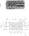
- the figure 5 gives an example of a corrugated sheet provided with a multitude of fins A having a triangular profile, similar to those described with reference to the figure 4A .
- the fins can be identical in order to optimize and facilitate the manufacturing process.
- the corrugated sheets with fins are stacked to form a structured packing.
- the direction of the channels of a corrugated sheet is offset with respect to the direction of the channels of the adjacent sheets, for example by an angle between 20° and 90°, preferably by an angle having a value substantially close 90°.
- the figure 6 represents a structured filling composed of corrugated sheets in a triangular pattern.
- the figure 7 represents a contacting column 30 consisting of a cylindrical enclosure 31 closed by the bottom parts 32 and 33.
- a fluid for example gas
- Another fluid by example of the liquid
- the column 30 is provided with internal packing on the height H which can reach several tens of meters.
- the structured packing is composed of corrugated sheets provided with fins, for example described with reference to the figure 5 and arranged for example according to an arrangement described with reference to the figure 6 .
- a packing composed of several blocks B1, B2, B3 and B4 is used in which the channels are oriented differently from one block to another.
- the plates constituting the structured packings are arranged so that the direction of the channels formed by the undulations forms an angle of between 10° and 75° with respect to the vertical, an excellent value of this angle being between 20 ° and 45°.
- the plates of a block are offset from adjacent blocks.
- the meridian planes of the plates of a block form an angle of between 20° and 90°, often equal to 90° with respect to the meridian planes of the plates constituting an adjacent block.
- the figure 8 represents two adjacent blocks formed by plates with triangular undulations.
- the lower structured packing block is composed of plates offset 90° from the plates of the upper structured packing block.
- the height h of a block can be limited to a limit value, for example between 50 and 500 mm, and preferably between 100 and 400 mm for the introduction of the blocks into the cylindrical enclosure during the assembly of the column.
- the packing according to the invention can be used for the deacidification of a natural gas, the decarbonation of flue gases and the treatment of tail gases from a Claus process.
- the gas to be treated is brought into contact with a liquid absorbent solution in a contacting column provided with a packing according to the invention.
- the packings are used in a process for deacidification of a gas comprising 10% vol. of CO 2 .
- the gas to be treated having a flow rate of 350,000 Nm 3 /h, is brought into contact with an aqueous solution of amines in a column comprising an internal packing.
- the absorption column is dimensioned so as to be able to absorb 90% of CO 2 .
- the three packings are chosen so as to offer the same hydraulic capacity.
- an identical column diameter can be fixed for the three packings. In this case, only the packing height in the column plays a role in the performance of the contacting column.
Landscapes
- Chemical & Material Sciences (AREA)
- Physics & Mathematics (AREA)
- Thermal Sciences (AREA)
- Organic Chemistry (AREA)
- Chemical Kinetics & Catalysis (AREA)
- Physical Or Chemical Processes And Apparatus (AREA)
- Vaporization, Distillation, Condensation, Sublimation, And Cold Traps (AREA)
Claims (10)
- Strukturierte Packung einer Fluidaustauschsäule, die eine Austauschoberfläche für mindestens eine flüssige Phase definiert, die dazu bestimmt ist, mit mindestens einer gasförmigen Phase in engen Kontakt zu kommen, wobei die Packung von einem Plattenstapel, umfassend Wellungen von dreieckiger Form, gebildet ist, wobei jede Platte zwischen zwei parallelen Ebenen (L1; L2) angeordnet ist, die um einen Wert (b) zwischen 5 und 50 mm entfernt sind, wobei die Wellungen eine Aufeinanderfolge von Kanälen bilden, die Flügel (A) umfassen, die zwischen den zwei parallelen Ebenen angeordnet sind, wobei jeder der Flügel von mindestens einem Streifen (B) gebildet ist, der aus einer der Platten entlang zweier Kerben (C1; C2) ausgeschnitten ist, wobei die Breite (L) des Streifens zwischen 2 und 20 mm beträgt, wobei der Streifen mit der Platte mit seinen zwei Enden (E1; E2) verbunden bleibt, und wobei der Streifen zum Dreieck verformt wird, um eine dreieckige Form im Wesentlichen symmetrisch zu seiner ursprünglichen Form in Bezug zu einer Mittelebene (P) der zwei Ebenen (L1; L2) zu erhalten, und um eine Öffnung zu erzeugen, die eine Diskontinuität auf der Oberfläche der Platte bildet, wobei die angrenzenden Flügel, die sich auf zwei aneinander anliegenden Kanälen befinden und von Streifen gebildet sind, die in entgegengesetzte Richtungen in Bezug zur Mittelebene (P) verformt sind, durch einen Raum (F) getrennt sind, wobei der Raum (F) in die Richtung (D) der Kanäle gemessen wird, und wobei die Kerben (C1; C2) der Flügel in einem Winkel zwischen 20° und 90° in Bezug zur Richtung (D) der Kanäle ausgerichtet sind.
- Packung nach Anspruch 1, bei der die Gesamtfläche der Flügel zwischen 20 % und 50 % der Gesamtfläche der Platten der strukturierten Packung darstellt.
- Packung nach einem der vorhergehenden Ansprüche, bei der die Richtung (D) der Kanäle einer Platte einen Winkel zwischen 20° und 90° in Bezug zur Richtung (D) der Kanäle einer angrenzenden Platte bildet.
- Packung nach einem der vorhergehenden Ansprüche, bei der jeder Flügel einen Scheitel umfasst, der um mindestens 2 mm von den zwei Ebenen entfernt ist.
- Packung nach einem der vorhergehenden Ansprüche, bei der jedes Ende des Streifens einen Winkel zwischen 85° und 95° mit der Platte bildet.
- Packung nach einem der vorhergehenden Ansprüche, bei der die entlang eines Kanals verteilten Flügel (A) unterschiedliche Formen haben.
- Packung nach einem der vorhergehenden Ansprüche, bei der der streifen (B) von länglicher Form ist, deren Hauptrichtung in einem Winkel im Wesentlichen gleich 90° in Bezug zur Richtung der Kanäle ausgerichtet ist.
- Packung nach einem der vorhergehenden Ansprüche, bei der die Platten mindestens eines der Materialien umfassen, das unter den metallischen Materialien, den thermoplastischen Polymermaterialien und den duroplastischen Polymermaterialien ausgewählt ist.
- Fluidkontaktsäule, umfassend mehrere Blöcke (B1-B4), umfassend strukturierte Packungen nach einem der vorhergehenden Ansprüche, bei der die Richtung der Kanäle der Packungen in einem Winkel zwischen 10° und 75° in Bezug zur Achse der Säule ausgerichtet ist, und bei der die Mittelebenen der strukturierten Packung eines der Blöcke einen Winkel zwischen 20° und 90° in Bezug zu den Mittelebenen der angrenzenden Blöcke bilden.
- Anwendung einer Kontaktsäule nach Anspruch 9 für die Entsäuerung eines Erdgases, die Entkarbonisierung der Rauchgase oder die Behandlung der Endgase eines Claus-Verfahrens.
Applications Claiming Priority (2)
| Application Number | Priority Date | Filing Date | Title |
|---|---|---|---|
| FR0701770A FR2913353B1 (fr) | 2007-03-09 | 2007-03-09 | Garnissage structure haute performance pour colonne de mise en contact de fluides et methode de fabrication. |
| PCT/FR2008/000291 WO2008132311A2 (fr) | 2007-03-09 | 2008-03-05 | Garnissage structure haute performance pour colonne de mise en contact de fluides et méthode de fabrication |
Publications (3)
| Publication Number | Publication Date |
|---|---|
| EP2134463A2 EP2134463A2 (de) | 2009-12-23 |
| EP2134463B1 EP2134463B1 (de) | 2018-11-28 |
| EP2134463B2 true EP2134463B2 (de) | 2022-07-27 |
Family
ID=38521694
Family Applications (1)
| Application Number | Title | Priority Date | Filing Date |
|---|---|---|---|
| EP08775631.8A Active EP2134463B2 (de) | 2007-03-09 | 2008-03-05 | Strukturierte hochleistungsverpackung für eine säule mit flüssigkeitskontakt und verfahren zu ihrer herstellung |
Country Status (4)
| Country | Link |
|---|---|
| US (1) | US8646758B2 (de) |
| EP (1) | EP2134463B2 (de) |
| FR (1) | FR2913353B1 (de) |
| WO (1) | WO2008132311A2 (de) |
Families Citing this family (26)
| Publication number | Priority date | Publication date | Assignee | Title |
|---|---|---|---|---|
| DE102009052045A1 (de) | 2009-11-05 | 2011-05-12 | Rvt Process Equipment Gmbh | Gewelltes Packungsgitter sowie geordnete, aus mehreren Packungsgittern aufgebaute Packung |
| FR2982171B1 (fr) | 2011-11-04 | 2013-11-08 | Ifp Energies Now | Procede de desacidification d'un gaz avec plusieurs etapes de mise en contact a courant croise avec une solution absorbante |
| JP2015502847A (ja) * | 2011-11-29 | 2015-01-29 | スルザー ケムテック アクチェンゲゼルシャフト | 二酸化炭素の吸収のための方法及び装置 |
| CN102764628B (zh) * | 2012-07-24 | 2014-10-22 | 天津大学 | 一种超低压降开窗导流填料片及规整填料 |
| FR2995223B1 (fr) * | 2012-09-11 | 2014-09-12 | IFP Energies Nouvelles | Garnissage structure haute performance pour colonne de mise en contact de fluides |
| FR2995224B1 (fr) * | 2012-09-11 | 2014-09-12 | IFP Energies Nouvelles | Garnissage haute performance pour colonne de mise en contact de fluides |
| FR2996148B1 (fr) | 2012-10-03 | 2015-11-06 | Euroslot Kdss France | Element de garnissage structure pour colonne de mise en contact de fluides |
| CN104984723B (zh) | 2013-08-30 | 2018-09-28 | 北京泽华化学工程有限公司 | 填料体及其层件、塔器和混合器 |
| US9162206B2 (en) | 2013-12-05 | 2015-10-20 | Exxonmobil Research And Engineering Company | Reactor bed component for securing rigid assemblies |
| FR3016533B1 (fr) | 2014-01-21 | 2016-01-15 | IFP Energies Nouvelles | Plateau distributeur pour colonne d'echange entre un gaz et un liquide avec deflecteur de liquide |
| FR3018200B1 (fr) | 2014-03-10 | 2017-12-01 | Ifp Energies Now | Contacteur pour colonne d'echange constitue de compartiments de garnissage vrac |
| FR3018201B1 (fr) | 2014-03-10 | 2016-02-26 | Ifp Energies Now | Contacteur pour colonne d'echange constitue d'un agencement de garnissages structures |
| FR3037507A1 (fr) | 2015-06-16 | 2016-12-23 | Ifp Energies Now | Contacteur pour colonne d'echange de chaleur et/ou de matiere comprenant un garnissage et au moins une zone de chute libre |
| US9839883B2 (en) * | 2016-03-18 | 2017-12-12 | Komax Systems, Inc. | Channel mixing apparatus |
| JP6862745B2 (ja) * | 2016-10-04 | 2021-04-21 | 株式会社Ihi | 気液接触装置 |
| USD854132S1 (en) | 2016-11-23 | 2019-07-16 | Koch-Glitsch, Lp | Corrugated steel structure |
| FR3059569B1 (fr) | 2016-12-07 | 2019-01-25 | IFP Energies Nouvelles | Colonne d'echange de chaleur et/ou de matiere entre un gaz et un liquide comprenant un contacteur et des moyens de restriction |
| FR3059570A1 (fr) * | 2016-12-07 | 2018-06-08 | IFP Energies Nouvelles | Procede de fabrication d'un garnissage structure par une methode de fabrication additive |
| FR3069019A1 (fr) | 2017-07-12 | 2019-01-18 | IFP Energies Nouvelles | Systeme et procede de stockage et de recuperation d'energie par gaz comprime avec echange de chaleur direct entre le gaz et un fluide |
| US10913044B2 (en) * | 2017-07-14 | 2021-02-09 | Technip Process Technology, Inc. | Device for gas solids fluidized system to enhance stripping |
| JP7047273B2 (ja) * | 2017-07-25 | 2022-04-05 | 株式会社Ihi | 親水化材料、親水化部材及びそれを用いた気液接触装置 |
| US10150054B1 (en) | 2017-11-30 | 2018-12-11 | Technip Process Technology, Inc. | Multi directional device for vapor-solid mixing |
| CN108671733B (zh) * | 2018-07-31 | 2023-05-02 | 太仓市宇格明叶环保设备有限公司 | 一种卧式交叉废气洗涤塔及其工作方法 |
| DE102018221652A1 (de) * | 2018-12-13 | 2020-06-18 | Sgl Carbon Se | Füllkörper |
| CN116510473A (zh) * | 2023-06-09 | 2023-08-01 | 湖北兴达石化设备有限公司 | 一种用于teg吸收塔高效脉冲规整填料 |
| FR3152814A1 (fr) | 2023-09-13 | 2025-03-14 | IFP Energies Nouvelles | Procédé de production d’alcools avec un support sur lequel sont immobilisés des micro-organismes |
Citations (2)
| Publication number | Priority date | Publication date | Assignee | Title |
|---|---|---|---|---|
| CN1127675A (zh) † | 1994-12-27 | 1996-07-31 | 天津市乾隆科技开发公司 | 波环填料 |
| WO2003004148A2 (fr) † | 2001-07-06 | 2003-01-16 | L'air Liquide Societe Anonyme A Directoire Et Conseil De Surveillance Pour L'etude Et L'exploitation Des Procedes Georges Claude | Bande pour module de garnissage, module et installation correspondants |
Family Cites Families (28)
| Publication number | Priority date | Publication date | Assignee | Title |
|---|---|---|---|---|
| US3158527A (en) * | 1960-06-10 | 1964-11-24 | Crown Zellerbach Corp | Plaited structure and method of forming same |
| DE1501375A1 (de) * | 1966-06-10 | 1970-01-22 | Escher Wyss Gmbh | Fuellkoerperplatten fuer Waerme- und Stoffaustausch-Vorrichtungen |
| AT313936B (de) * | 1969-07-14 | 1974-03-11 | Faigle Heinz | Rieseleinbau, insbesondere für Kühltürme |
| AT321865B (de) * | 1970-04-27 | 1975-04-25 | Dl Veb Maschinen Und Appbau Gr | Hochleistung sa ustauschpackung für kolonnen |
| GB1541432A (en) * | 1975-01-29 | 1979-02-28 | Citten Ltd | Dumped packings and apparatus comprising such dumped packings |
| DD154153A3 (de) * | 1980-08-13 | 1982-03-03 | Klaus Hoppe | Kolonnenpackung fuer stoff-und waermeuebertragung |
| EP0070915A1 (de) * | 1981-07-30 | 1983-02-09 | GebràDer Sulzer Aktiengesellschaft | Einbauelement für eine Vorrichtung für Stoff- und direkten Wärmeaustausch und Mischen |
| US4600544A (en) * | 1982-11-29 | 1986-07-15 | Merix Corporation | Packing unit and method of making |
| NL8301901A (nl) * | 1983-05-27 | 1984-12-17 | Fdo Techn Adviseurs | Inrichting voor het uitvoeren van een stofwisselingsproces. |
| DE8330573U1 (de) * | 1983-10-25 | 1984-02-02 | Vereinigte Füllkörper-Fabriken GmbH & Co, 5412 Ransbach-Baumbach | Fuellkoerper fuer stoffaustauschkolonnen |
| US4576763A (en) * | 1984-06-27 | 1986-03-18 | Nutter Dale E | Packings for gas-liquid contact apparatus |
| US4676934A (en) * | 1985-09-27 | 1987-06-30 | Jaeger Products, Inc. | Structured WV packing elements |
| US4710326A (en) * | 1986-08-29 | 1987-12-01 | Seah Alexander M | Corrugated packing and methods of use |
| US5063000A (en) * | 1989-05-03 | 1991-11-05 | Mix Thomas W | Packing elements |
| DE8908738U1 (de) * | 1989-07-18 | 1989-09-07 | Emitec Gesellschaft für Emissionstechnologie mbH, 5204 Lohmar | Wabenkörper mit internen Strömungsleitflächen, insbesondere Katalysatorkörper für Kraftfahrzeuge |
| DE4002257A1 (de) | 1990-01-26 | 1991-08-01 | Tomka Ivan | Einkapselung von wirkstoffen mittels staerke |
| US5407607A (en) * | 1993-11-09 | 1995-04-18 | Mix; Thomas W. | Structured packing elements |
| EP0671207B1 (de) * | 1994-03-09 | 2000-05-03 | Sulzer Chemtech AG | Flächiges Struckturelement und daraus gebildete Packung |
| JP2000517466A (ja) * | 1996-09-04 | 2000-12-26 | シーメンス アクチエンゲゼルシヤフト | 2つの部材を熱的、電気的および機械的に結合するための中間部材 |
| DE19733480C2 (de) * | 1997-08-01 | 1999-06-24 | Gea Kuehlturmbau Gmbh | Einbaupackung zum Stoff- und/oder Wärmeaustausch zwischen Gasen und Flüssigkeiten |
| US6276045B1 (en) * | 1998-10-28 | 2001-08-21 | Abb Lummus Global, Inc. | Method and apparatus for making structured packing element |
| EP1029588B2 (de) * | 1999-02-12 | 2007-09-05 | Sulzer Chemtech AG | Füllkörper mit Kreuzkanalstruktur |
| TW443941B (en) * | 1999-02-12 | 2001-07-01 | Sulzer Chemtech Ag | Filler body with a cross channel structure |
| FR2867697B1 (fr) * | 2004-03-16 | 2007-06-01 | Air Liquide | Structure de garnissage ondule-croise |
| US7332132B2 (en) * | 2004-03-19 | 2008-02-19 | Uop Llc | Stripping apparatus and process |
| FR2871074B1 (fr) * | 2004-06-04 | 2007-03-16 | Air Liquide | Bande pour module de garnissage, module de garnissage et installation de distillation correspondants |
| FR2871073B1 (fr) | 2004-06-04 | 2007-04-13 | Air Liquide | Bande pour module de garnissage ondule-croise, procede de fabrication et module de garnissage ondule-croise correspondants |
| GB0603609D0 (en) * | 2006-02-23 | 2006-04-05 | Accentus Plc | Catalyst structure |
-
2007
- 2007-03-09 FR FR0701770A patent/FR2913353B1/fr active Active
-
2008
- 2008-03-05 WO PCT/FR2008/000291 patent/WO2008132311A2/fr not_active Ceased
- 2008-03-05 EP EP08775631.8A patent/EP2134463B2/de active Active
- 2008-03-05 US US12/530,528 patent/US8646758B2/en active Active
Patent Citations (2)
| Publication number | Priority date | Publication date | Assignee | Title |
|---|---|---|---|---|
| CN1127675A (zh) † | 1994-12-27 | 1996-07-31 | 天津市乾隆科技开发公司 | 波环填料 |
| WO2003004148A2 (fr) † | 2001-07-06 | 2003-01-16 | L'air Liquide Societe Anonyme A Directoire Et Conseil De Surveillance Pour L'etude Et L'exploitation Des Procedes Georges Claude | Bande pour module de garnissage, module et installation correspondants |
Also Published As
| Publication number | Publication date |
|---|---|
| FR2913353A1 (fr) | 2008-09-12 |
| EP2134463A2 (de) | 2009-12-23 |
| US8646758B2 (en) | 2014-02-11 |
| WO2008132311A2 (fr) | 2008-11-06 |
| EP2134463B1 (de) | 2018-11-28 |
| WO2008132311A3 (fr) | 2008-12-24 |
| FR2913353B1 (fr) | 2010-05-21 |
| US20100213625A1 (en) | 2010-08-26 |
Similar Documents
| Publication | Publication Date | Title |
|---|---|---|
| EP2134463B1 (de) | Strukturierte hochleistungsverpackung für eine säule mit flüssigkeitskontakt und verfahren zu ihrer herstellung | |
| EP2129459B1 (de) | Packungsstruktur für eine flüssigkeitskontaktsäule und verfahren zu ihrer herstellung | |
| CA2881773C (fr) | Garnissage structure haute performance pour colonne de mise en contact de fluides | |
| RU2520767C1 (ru) | Теплообменная пластина и пластинчатый теплообменник | |
| WO2010070216A1 (fr) | Échangeur de chaleur comprenant des tubes a ailettes rainurées | |
| EP2895263B1 (de) | Strukturierte hochleistungsverkapselung für eine flüssigkeitskontaktsäule | |
| EP3132222B1 (de) | Wärmeaustauschermodul, verwendung mit flüssigmetall und gas | |
| EP3296678A1 (de) | Vereinfachter enthalpie-wärmetauscher | |
| FR2848292A1 (fr) | Plaque d'un echangeur thermique et echangeur thermique a plaques | |
| FR2930466A1 (fr) | Cale pour le maintien des passages d'echangeurs a plaques et ailettes brases | |
| FR2996148A1 (fr) | Element de garnissage structure pour colonne de mise en contact de fluides | |
| EP1727617A1 (de) | Gewellte überkreuz-füllungs-struktur | |
| WO2010058115A1 (fr) | Garnissage ondulé-croisé et colonne incorporant un tel garnissage | |
| FR3018200A1 (fr) | Contacteur pour colonne d'echange constitue de compartiments de garnissage vrac | |
| EP3144060B1 (de) | Struktur für optimierte auskleidung für eine flüssigkeitskontaktsäule, und herstellungsverfahren | |
| WO2003049854A2 (fr) | Bande pour module de garnissage, module et colonne correspondants | |
| EP3105520B1 (de) | Säule zur trennung von luft durch kryogene destillation, lufttrennungsvorrichtung mit solch einer säule und verfahren zur herstellung solch einer säule | |
| WO2018172685A1 (fr) | Echangeur de chaleur avec dispositif melangeur liquide/gaz a orifices de forme amelioree | |
| WO2018104124A1 (fr) | Procede de fabrication d'un garnissage structure par une methode de fabrication additive | |
| WO2019191375A1 (en) | Multi-channel distillation column packing | |
| EP3728978B1 (de) | Wärmetauscher mit übereinander angeordneten abstandshaltern | |
| FR3133077A3 (fr) | Echangeur de chaleur à structure d’échange thermique améliorée | |
| FR2827526A1 (fr) | Bande d'interface,garnissage correspondant,et appareil de traitement de fluide(s) correspondant. | |
| FR2915111A1 (fr) | Colonne d'echange de matiere et/ou de chaleur a garnissages structures. | |
| FR2947188A1 (fr) | Bande pour module de garnissage, module de garnissage et installation de distillation correspondants |
Legal Events
| Date | Code | Title | Description |
|---|---|---|---|
| PUAI | Public reference made under article 153(3) epc to a published international application that has entered the european phase |
Free format text: ORIGINAL CODE: 0009012 |
|
| 17P | Request for examination filed |
Effective date: 20091009 |
|
| AK | Designated contracting states |
Kind code of ref document: A2 Designated state(s): AT BE BG CH CY CZ DE DK EE ES FI FR GB GR HR HU IE IS IT LI LT LU LV MC MT NL NO PL PT RO SE SI SK TR |
|
| RIN1 | Information on inventor provided before grant (corrected) |
Inventor name: ALIX, PASCAL Inventor name: RAYNAL, LUDOVIC |
|
| 17Q | First examination report despatched |
Effective date: 20100203 |
|
| RAP1 | Party data changed (applicant data changed or rights of an application transferred) |
Owner name: IFP ENERGIES NOUVELLES |
|
| DAX | Request for extension of the european patent (deleted) | ||
| TPAC | Observations filed by third parties |
Free format text: ORIGINAL CODE: EPIDOSNTIPA |
|
| RAP1 | Party data changed (applicant data changed or rights of an application transferred) |
Owner name: IFP ENERGIES NOUVELLES |
|
| GRAP | Despatch of communication of intention to grant a patent |
Free format text: ORIGINAL CODE: EPIDOSNIGR1 |
|
| STAA | Information on the status of an ep patent application or granted ep patent |
Free format text: STATUS: GRANT OF PATENT IS INTENDED |
|
| INTG | Intention to grant announced |
Effective date: 20180620 |
|
| GRAS | Grant fee paid |
Free format text: ORIGINAL CODE: EPIDOSNIGR3 |
|
| GRAA | (expected) grant |
Free format text: ORIGINAL CODE: 0009210 |
|
| STAA | Information on the status of an ep patent application or granted ep patent |
Free format text: STATUS: THE PATENT HAS BEEN GRANTED |
|
| AK | Designated contracting states |
Kind code of ref document: B1 Designated state(s): AT BE BG CH CY CZ DE DK EE ES FI FR GB GR HR HU IE IS IT LI LT LU LV MC MT NL NO PL PT RO SE SI SK TR |
|
| REG | Reference to a national code |
Ref country code: GB Ref legal event code: FG4D Free format text: NOT ENGLISH |
|
| REG | Reference to a national code |
Ref country code: CH Ref legal event code: EP |
|
| REG | Reference to a national code |
Ref country code: AT Ref legal event code: REF Ref document number: 1069591 Country of ref document: AT Kind code of ref document: T Effective date: 20181215 |
|
| REG | Reference to a national code |
Ref country code: DE Ref legal event code: R096 Ref document number: 602008058118 Country of ref document: DE |
|
| REG | Reference to a national code |
Ref country code: IE Ref legal event code: FG4D Free format text: LANGUAGE OF EP DOCUMENT: FRENCH |
|
| REG | Reference to a national code |
Ref country code: NL Ref legal event code: MP Effective date: 20181128 |
|
| REG | Reference to a national code |
Ref country code: LT Ref legal event code: MG4D |
|
| REG | Reference to a national code |
Ref country code: AT Ref legal event code: MK05 Ref document number: 1069591 Country of ref document: AT Kind code of ref document: T Effective date: 20181128 |
|
| PG25 | Lapsed in a contracting state [announced via postgrant information from national office to epo] |
Ref country code: ES Free format text: LAPSE BECAUSE OF FAILURE TO SUBMIT A TRANSLATION OF THE DESCRIPTION OR TO PAY THE FEE WITHIN THE PRESCRIBED TIME-LIMIT Effective date: 20181128 Ref country code: LV Free format text: LAPSE BECAUSE OF FAILURE TO SUBMIT A TRANSLATION OF THE DESCRIPTION OR TO PAY THE FEE WITHIN THE PRESCRIBED TIME-LIMIT Effective date: 20181128 Ref country code: AT Free format text: LAPSE BECAUSE OF FAILURE TO SUBMIT A TRANSLATION OF THE DESCRIPTION OR TO PAY THE FEE WITHIN THE PRESCRIBED TIME-LIMIT Effective date: 20181128 Ref country code: FI Free format text: LAPSE BECAUSE OF FAILURE TO SUBMIT A TRANSLATION OF THE DESCRIPTION OR TO PAY THE FEE WITHIN THE PRESCRIBED TIME-LIMIT Effective date: 20181128 Ref country code: IS Free format text: LAPSE BECAUSE OF FAILURE TO SUBMIT A TRANSLATION OF THE DESCRIPTION OR TO PAY THE FEE WITHIN THE PRESCRIBED TIME-LIMIT Effective date: 20190328 Ref country code: BG Free format text: LAPSE BECAUSE OF FAILURE TO SUBMIT A TRANSLATION OF THE DESCRIPTION OR TO PAY THE FEE WITHIN THE PRESCRIBED TIME-LIMIT Effective date: 20190228 Ref country code: HR Free format text: LAPSE BECAUSE OF FAILURE TO SUBMIT A TRANSLATION OF THE DESCRIPTION OR TO PAY THE FEE WITHIN THE PRESCRIBED TIME-LIMIT Effective date: 20181128 Ref country code: NO Free format text: LAPSE BECAUSE OF FAILURE TO SUBMIT A TRANSLATION OF THE DESCRIPTION OR TO PAY THE FEE WITHIN THE PRESCRIBED TIME-LIMIT Effective date: 20190228 Ref country code: LT Free format text: LAPSE BECAUSE OF FAILURE TO SUBMIT A TRANSLATION OF THE DESCRIPTION OR TO PAY THE FEE WITHIN THE PRESCRIBED TIME-LIMIT Effective date: 20181128 |
|
| PG25 | Lapsed in a contracting state [announced via postgrant information from national office to epo] |
Ref country code: PT Free format text: LAPSE BECAUSE OF FAILURE TO SUBMIT A TRANSLATION OF THE DESCRIPTION OR TO PAY THE FEE WITHIN THE PRESCRIBED TIME-LIMIT Effective date: 20190328 Ref country code: GR Free format text: LAPSE BECAUSE OF FAILURE TO SUBMIT A TRANSLATION OF THE DESCRIPTION OR TO PAY THE FEE WITHIN THE PRESCRIBED TIME-LIMIT Effective date: 20190301 Ref country code: SE Free format text: LAPSE BECAUSE OF FAILURE TO SUBMIT A TRANSLATION OF THE DESCRIPTION OR TO PAY THE FEE WITHIN THE PRESCRIBED TIME-LIMIT Effective date: 20181128 |
|
| PG25 | Lapsed in a contracting state [announced via postgrant information from national office to epo] |
Ref country code: NL Free format text: LAPSE BECAUSE OF FAILURE TO SUBMIT A TRANSLATION OF THE DESCRIPTION OR TO PAY THE FEE WITHIN THE PRESCRIBED TIME-LIMIT Effective date: 20181128 |
|
| PG25 | Lapsed in a contracting state [announced via postgrant information from national office to epo] |
Ref country code: PL Free format text: LAPSE BECAUSE OF FAILURE TO SUBMIT A TRANSLATION OF THE DESCRIPTION OR TO PAY THE FEE WITHIN THE PRESCRIBED TIME-LIMIT Effective date: 20181128 Ref country code: CZ Free format text: LAPSE BECAUSE OF FAILURE TO SUBMIT A TRANSLATION OF THE DESCRIPTION OR TO PAY THE FEE WITHIN THE PRESCRIBED TIME-LIMIT Effective date: 20181128 Ref country code: DK Free format text: LAPSE BECAUSE OF FAILURE TO SUBMIT A TRANSLATION OF THE DESCRIPTION OR TO PAY THE FEE WITHIN THE PRESCRIBED TIME-LIMIT Effective date: 20181128 |
|
| REG | Reference to a national code |
Ref country code: DE Ref legal event code: R026 Ref document number: 602008058118 Country of ref document: DE |
|
| PG25 | Lapsed in a contracting state [announced via postgrant information from national office to epo] |
Ref country code: RO Free format text: LAPSE BECAUSE OF FAILURE TO SUBMIT A TRANSLATION OF THE DESCRIPTION OR TO PAY THE FEE WITHIN THE PRESCRIBED TIME-LIMIT Effective date: 20181128 Ref country code: SK Free format text: LAPSE BECAUSE OF FAILURE TO SUBMIT A TRANSLATION OF THE DESCRIPTION OR TO PAY THE FEE WITHIN THE PRESCRIBED TIME-LIMIT Effective date: 20181128 Ref country code: EE Free format text: LAPSE BECAUSE OF FAILURE TO SUBMIT A TRANSLATION OF THE DESCRIPTION OR TO PAY THE FEE WITHIN THE PRESCRIBED TIME-LIMIT Effective date: 20181128 |
|
| PLBI | Opposition filed |
Free format text: ORIGINAL CODE: 0009260 |
|
| PLAX | Notice of opposition and request to file observation + time limit sent |
Free format text: ORIGINAL CODE: EPIDOSNOBS2 |
|
| 26 | Opposition filed |
Opponent name: L'AIR LIQUIDE, SOCIETE ANONYME POUR L'ETUDE ET L'E Effective date: 20190826 |
|
| PG25 | Lapsed in a contracting state [announced via postgrant information from national office to epo] |
Ref country code: SI Free format text: LAPSE BECAUSE OF FAILURE TO SUBMIT A TRANSLATION OF THE DESCRIPTION OR TO PAY THE FEE WITHIN THE PRESCRIBED TIME-LIMIT Effective date: 20181128 Ref country code: MC Free format text: LAPSE BECAUSE OF FAILURE TO SUBMIT A TRANSLATION OF THE DESCRIPTION OR TO PAY THE FEE WITHIN THE PRESCRIBED TIME-LIMIT Effective date: 20181128 |
|
| GBPC | Gb: european patent ceased through non-payment of renewal fee |
Effective date: 20190305 |
|
| PG25 | Lapsed in a contracting state [announced via postgrant information from national office to epo] |
Ref country code: LU Free format text: LAPSE BECAUSE OF NON-PAYMENT OF DUE FEES Effective date: 20190305 |
|
| REG | Reference to a national code |
Ref country code: BE Ref legal event code: MM Effective date: 20190331 |
|
| PLBB | Reply of patent proprietor to notice(s) of opposition received |
Free format text: ORIGINAL CODE: EPIDOSNOBS3 |
|
| PG25 | Lapsed in a contracting state [announced via postgrant information from national office to epo] |
Ref country code: GB Free format text: LAPSE BECAUSE OF NON-PAYMENT OF DUE FEES Effective date: 20190305 Ref country code: IE Free format text: LAPSE BECAUSE OF NON-PAYMENT OF DUE FEES Effective date: 20190305 |
|
| PG25 | Lapsed in a contracting state [announced via postgrant information from national office to epo] |
Ref country code: BE Free format text: LAPSE BECAUSE OF NON-PAYMENT OF DUE FEES Effective date: 20190331 |
|
| PG25 | Lapsed in a contracting state [announced via postgrant information from national office to epo] |
Ref country code: TR Free format text: LAPSE BECAUSE OF FAILURE TO SUBMIT A TRANSLATION OF THE DESCRIPTION OR TO PAY THE FEE WITHIN THE PRESCRIBED TIME-LIMIT Effective date: 20181128 |
|
| PLAY | Examination report in opposition despatched + time limit |
Free format text: ORIGINAL CODE: EPIDOSNORE2 |
|
| PG25 | Lapsed in a contracting state [announced via postgrant information from national office to epo] |
Ref country code: MT Free format text: LAPSE BECAUSE OF FAILURE TO SUBMIT A TRANSLATION OF THE DESCRIPTION OR TO PAY THE FEE WITHIN THE PRESCRIBED TIME-LIMIT Effective date: 20181128 |
|
| PLBC | Reply to examination report in opposition received |
Free format text: ORIGINAL CODE: EPIDOSNORE3 |
|
| PLAB | Opposition data, opponent's data or that of the opponent's representative modified |
Free format text: ORIGINAL CODE: 0009299OPPO |
|
| R26 | Opposition filed (corrected) |
Opponent name: L'AIR LIQUIDE, SOCIETE ANONYME POUR L'ETUDE ET L'EXPLOITATION DES PROCEDES GEORGES CLAUDE Effective date: 20190826 |
|
| PG25 | Lapsed in a contracting state [announced via postgrant information from national office to epo] |
Ref country code: CY Free format text: LAPSE BECAUSE OF FAILURE TO SUBMIT A TRANSLATION OF THE DESCRIPTION OR TO PAY THE FEE WITHIN THE PRESCRIBED TIME-LIMIT Effective date: 20181128 |
|
| PG25 | Lapsed in a contracting state [announced via postgrant information from national office to epo] |
Ref country code: HU Free format text: LAPSE BECAUSE OF FAILURE TO SUBMIT A TRANSLATION OF THE DESCRIPTION OR TO PAY THE FEE WITHIN THE PRESCRIBED TIME-LIMIT; INVALID AB INITIO Effective date: 20080305 |
|
| PUAH | Patent maintained in amended form |
Free format text: ORIGINAL CODE: 0009272 |
|
| STAA | Information on the status of an ep patent application or granted ep patent |
Free format text: STATUS: PATENT MAINTAINED AS AMENDED |
|
| 27A | Patent maintained in amended form |
Effective date: 20220727 |
|
| AK | Designated contracting states |
Kind code of ref document: B2 Designated state(s): AT BE BG CH CY CZ DE DK EE ES FI FR GB GR HR HU IE IS IT LI LT LU LV MC MT NL NO PL PT RO SE SI SK TR |
|
| REG | Reference to a national code |
Ref country code: DE Ref legal event code: R102 Ref document number: 602008058118 Country of ref document: DE |
|
| P01 | Opt-out of the competence of the unified patent court (upc) registered |
Effective date: 20230712 |
|
| REG | Reference to a national code |
Ref country code: CH Ref legal event code: U11 Free format text: ST27 STATUS EVENT CODE: U-0-0-U10-U11 (AS PROVIDED BY THE NATIONAL OFFICE) Effective date: 20260401 |
|
| PGFP | Annual fee paid to national office [announced via postgrant information from national office to epo] |
Ref country code: DE Payment date: 20260320 Year of fee payment: 19 |
|
| PGFP | Annual fee paid to national office [announced via postgrant information from national office to epo] |
Ref country code: IT Payment date: 20260320 Year of fee payment: 19 |
|
| PGFP | Annual fee paid to national office [announced via postgrant information from national office to epo] |
Ref country code: FR Payment date: 20260323 Year of fee payment: 19 |
|
| PGFP | Annual fee paid to national office [announced via postgrant information from national office to epo] |
Ref country code: CH Payment date: 20260401 Year of fee payment: 19 |