EP3144060B1 - Struktur für optimierte auskleidung für eine flüssigkeitskontaktsäule, und herstellungsverfahren - Google Patents
Struktur für optimierte auskleidung für eine flüssigkeitskontaktsäule, und herstellungsverfahren Download PDFInfo
- Publication number
- EP3144060B1 EP3144060B1 EP16188390.5A EP16188390A EP3144060B1 EP 3144060 B1 EP3144060 B1 EP 3144060B1 EP 16188390 A EP16188390 A EP 16188390A EP 3144060 B1 EP3144060 B1 EP 3144060B1
- Authority
- EP
- European Patent Office
- Prior art keywords
- tubes
- tube
- rectangular parallelepiped
- orifices
- previous
- Prior art date
- Legal status (The legal status is an assumption and is not a legal conclusion. Google has not performed a legal analysis and makes no representation as to the accuracy of the status listed.)
- Not-in-force
Links
Images


Classifications
-
- B—PERFORMING OPERATIONS; TRANSPORTING
- B01—PHYSICAL OR CHEMICAL PROCESSES OR APPARATUS IN GENERAL
- B01J—CHEMICAL OR PHYSICAL PROCESSES, e.g. CATALYSIS OR COLLOID CHEMISTRY; THEIR RELEVANT APPARATUS
- B01J19/00—Chemical, physical or physico-chemical processes in general; Their relevant apparatus
- B01J19/30—Loose or shaped packing elements, e.g. Raschig rings or Berl saddles, for pouring into the apparatus for mass or heat transfer
-
- B—PERFORMING OPERATIONS; TRANSPORTING
- B01—PHYSICAL OR CHEMICAL PROCESSES OR APPARATUS IN GENERAL
- B01J—CHEMICAL OR PHYSICAL PROCESSES, e.g. CATALYSIS OR COLLOID CHEMISTRY; THEIR RELEVANT APPARATUS
- B01J19/00—Chemical, physical or physico-chemical processes in general; Their relevant apparatus
- B01J19/32—Packing elements in the form of grids or built-up elements for forming a unit or module inside the apparatus for mass or heat transfer
-
- B—PERFORMING OPERATIONS; TRANSPORTING
- B01—PHYSICAL OR CHEMICAL PROCESSES OR APPARATUS IN GENERAL
- B01D—SEPARATION
- B01D3/00—Distillation or related exchange processes in which liquids are contacted with gaseous media, e.g. stripping
- B01D3/14—Fractional distillation or use of a fractionation or rectification column
- B01D3/16—Fractionating columns in which vapour bubbles through liquid
-
- B—PERFORMING OPERATIONS; TRANSPORTING
- B01—PHYSICAL OR CHEMICAL PROCESSES OR APPARATUS IN GENERAL
- B01D—SEPARATION
- B01D3/00—Distillation or related exchange processes in which liquids are contacted with gaseous media, e.g. stripping
- B01D3/14—Fractional distillation or use of a fractionation or rectification column
- B01D3/26—Fractionating columns in which vapour and liquid flow past each other, or in which the fluid is sprayed into the vapour, or in which a two-phase mixture is passed in one direction
- B01D3/28—Fractionating columns with surface contact and vertical guides, e.g. film action
-
- B—PERFORMING OPERATIONS; TRANSPORTING
- B01—PHYSICAL OR CHEMICAL PROCESSES OR APPARATUS IN GENERAL
- B01D—SEPARATION
- B01D53/00—Separation of gases or vapours; Recovering vapours of volatile solvents from gases; Chemical or biological purification of waste gases, e.g. engine exhaust gases, smoke, fumes, flue gases, aerosols
- B01D53/14—Separation of gases or vapours; Recovering vapours of volatile solvents from gases; Chemical or biological purification of waste gases, e.g. engine exhaust gases, smoke, fumes, flue gases, aerosols by absorption
- B01D53/1456—Removing acid components
-
- B—PERFORMING OPERATIONS; TRANSPORTING
- B01—PHYSICAL OR CHEMICAL PROCESSES OR APPARATUS IN GENERAL
- B01D—SEPARATION
- B01D53/00—Separation of gases or vapours; Recovering vapours of volatile solvents from gases; Chemical or biological purification of waste gases, e.g. engine exhaust gases, smoke, fumes, flue gases, aerosols
- B01D53/14—Separation of gases or vapours; Recovering vapours of volatile solvents from gases; Chemical or biological purification of waste gases, e.g. engine exhaust gases, smoke, fumes, flue gases, aerosols by absorption
- B01D53/18—Absorbing units; Liquid distributors therefor
- B01D53/185—Liquid distributors
-
- B—PERFORMING OPERATIONS; TRANSPORTING
- B01—PHYSICAL OR CHEMICAL PROCESSES OR APPARATUS IN GENERAL
- B01D—SEPARATION
- B01D53/00—Separation of gases or vapours; Recovering vapours of volatile solvents from gases; Chemical or biological purification of waste gases, e.g. engine exhaust gases, smoke, fumes, flue gases, aerosols
- B01D53/34—Chemical or biological purification of waste gases
- B01D53/38—Removing components of undefined structure
- B01D53/40—Acidic components
-
- B—PERFORMING OPERATIONS; TRANSPORTING
- B01—PHYSICAL OR CHEMICAL PROCESSES OR APPARATUS IN GENERAL
- B01D—SEPARATION
- B01D53/00—Separation of gases or vapours; Recovering vapours of volatile solvents from gases; Chemical or biological purification of waste gases, e.g. engine exhaust gases, smoke, fumes, flue gases, aerosols
- B01D53/34—Chemical or biological purification of waste gases
- B01D53/74—General processes for purification of waste gases; Apparatus or devices specially adapted therefor
- B01D53/77—Liquid phase processes
- B01D53/78—Liquid phase processes with gas-liquid contact
-
- B—PERFORMING OPERATIONS; TRANSPORTING
- B01—PHYSICAL OR CHEMICAL PROCESSES OR APPARATUS IN GENERAL
- B01J—CHEMICAL OR PHYSICAL PROCESSES, e.g. CATALYSIS OR COLLOID CHEMISTRY; THEIR RELEVANT APPARATUS
- B01J20/00—Solid sorbent compositions or filter aid compositions; Sorbents for chromatography; Processes for preparing, regenerating or reactivating thereof
- B01J20/02—Solid sorbent compositions or filter aid compositions; Sorbents for chromatography; Processes for preparing, regenerating or reactivating thereof comprising inorganic material
- B01J20/20—Solid sorbent compositions or filter aid compositions; Sorbents for chromatography; Processes for preparing, regenerating or reactivating thereof comprising inorganic material comprising free carbon; comprising carbon obtained by carbonising processes
-
- B—PERFORMING OPERATIONS; TRANSPORTING
- B01—PHYSICAL OR CHEMICAL PROCESSES OR APPARATUS IN GENERAL
- B01J—CHEMICAL OR PHYSICAL PROCESSES, e.g. CATALYSIS OR COLLOID CHEMISTRY; THEIR RELEVANT APPARATUS
- B01J20/00—Solid sorbent compositions or filter aid compositions; Sorbents for chromatography; Processes for preparing, regenerating or reactivating thereof
- B01J20/22—Solid sorbent compositions or filter aid compositions; Sorbents for chromatography; Processes for preparing, regenerating or reactivating thereof comprising organic material
- B01J20/26—Synthetic macromolecular compounds
-
- B—PERFORMING OPERATIONS; TRANSPORTING
- B01—PHYSICAL OR CHEMICAL PROCESSES OR APPARATUS IN GENERAL
- B01J—CHEMICAL OR PHYSICAL PROCESSES, e.g. CATALYSIS OR COLLOID CHEMISTRY; THEIR RELEVANT APPARATUS
- B01J20/00—Solid sorbent compositions or filter aid compositions; Sorbents for chromatography; Processes for preparing, regenerating or reactivating thereof
- B01J20/28—Solid sorbent compositions or filter aid compositions; Sorbents for chromatography; Processes for preparing, regenerating or reactivating thereof characterised by their form or physical properties
- B01J20/28014—Solid sorbent compositions or filter aid compositions; Sorbents for chromatography; Processes for preparing, regenerating or reactivating thereof characterised by their form or physical properties characterised by their form
- B01J20/28023—Fibres or filaments
-
- B—PERFORMING OPERATIONS; TRANSPORTING
- B01—PHYSICAL OR CHEMICAL PROCESSES OR APPARATUS IN GENERAL
- B01J—CHEMICAL OR PHYSICAL PROCESSES, e.g. CATALYSIS OR COLLOID CHEMISTRY; THEIR RELEVANT APPARATUS
- B01J20/00—Solid sorbent compositions or filter aid compositions; Sorbents for chromatography; Processes for preparing, regenerating or reactivating thereof
- B01J20/28—Solid sorbent compositions or filter aid compositions; Sorbents for chromatography; Processes for preparing, regenerating or reactivating thereof characterised by their form or physical properties
- B01J20/28014—Solid sorbent compositions or filter aid compositions; Sorbents for chromatography; Processes for preparing, regenerating or reactivating thereof characterised by their form or physical properties characterised by their form
- B01J20/28052—Several layers of identical or different sorbents stacked in a housing, e.g. in a column
-
- B—PERFORMING OPERATIONS; TRANSPORTING
- B01—PHYSICAL OR CHEMICAL PROCESSES OR APPARATUS IN GENERAL
- B01J—CHEMICAL OR PHYSICAL PROCESSES, e.g. CATALYSIS OR COLLOID CHEMISTRY; THEIR RELEVANT APPARATUS
- B01J20/00—Solid sorbent compositions or filter aid compositions; Sorbents for chromatography; Processes for preparing, regenerating or reactivating thereof
- B01J20/28—Solid sorbent compositions or filter aid compositions; Sorbents for chromatography; Processes for preparing, regenerating or reactivating thereof characterised by their form or physical properties
- B01J20/28054—Solid sorbent compositions or filter aid compositions; Sorbents for chromatography; Processes for preparing, regenerating or reactivating thereof characterised by their form or physical properties characterised by their surface properties or porosity
- B01J20/28057—Surface area, e.g. B.E.T specific surface area
- B01J20/28059—Surface area, e.g. B.E.T specific surface area being less than 100 m2/g
-
- B—PERFORMING OPERATIONS; TRANSPORTING
- B01—PHYSICAL OR CHEMICAL PROCESSES OR APPARATUS IN GENERAL
- B01J—CHEMICAL OR PHYSICAL PROCESSES, e.g. CATALYSIS OR COLLOID CHEMISTRY; THEIR RELEVANT APPARATUS
- B01J20/00—Solid sorbent compositions or filter aid compositions; Sorbents for chromatography; Processes for preparing, regenerating or reactivating thereof
- B01J20/281—Sorbents specially adapted for preparative, analytical or investigative chromatography
- B01J20/282—Porous sorbents
-
- B—PERFORMING OPERATIONS; TRANSPORTING
- B01—PHYSICAL OR CHEMICAL PROCESSES OR APPARATUS IN GENERAL
- B01J—CHEMICAL OR PHYSICAL PROCESSES, e.g. CATALYSIS OR COLLOID CHEMISTRY; THEIR RELEVANT APPARATUS
- B01J20/00—Solid sorbent compositions or filter aid compositions; Sorbents for chromatography; Processes for preparing, regenerating or reactivating thereof
- B01J20/30—Processes for preparing, regenerating, or reactivating
- B01J20/3092—Packing of a container, e.g. packing a cartridge or column
-
- C—CHEMISTRY; METALLURGY
- C10—PETROLEUM, GAS OR COKE INDUSTRIES; TECHNICAL GASES CONTAINING CARBON MONOXIDE; FUELS; LUBRICANTS; PEAT
- C10L—FUELS NOT OTHERWISE PROVIDED FOR; NATURAL GAS; SYNTHETIC NATURAL GAS OBTAINED BY PROCESSES NOT COVERED BY SUBCLASSES C10G OR C10K; LIQUIFIED PETROLEUM GAS; USE OF ADDITIVES TO FUELS OR FIRES; FIRE-LIGHTERS
- C10L3/00—Gaseous fuels; Natural gas; Synthetic natural gas obtained by processes not covered by subclass C10G, C10K; Liquefied petroleum gas
- C10L3/06—Natural gas; Synthetic natural gas obtained by processes not covered by C10G, C10K3/02 or C10K3/04
- C10L3/10—Working-up natural gas or synthetic natural gas
- C10L3/101—Removal of contaminants
-
- B—PERFORMING OPERATIONS; TRANSPORTING
- B01—PHYSICAL OR CHEMICAL PROCESSES OR APPARATUS IN GENERAL
- B01J—CHEMICAL OR PHYSICAL PROCESSES, e.g. CATALYSIS OR COLLOID CHEMISTRY; THEIR RELEVANT APPARATUS
- B01J2219/00—Chemical, physical or physico-chemical processes in general; Their relevant apparatus
- B01J2219/30—Details relating to random packing elements
- B01J2219/302—Basic shape of the elements
- B01J2219/30223—Cylinder
-
- B—PERFORMING OPERATIONS; TRANSPORTING
- B01—PHYSICAL OR CHEMICAL PROCESSES OR APPARATUS IN GENERAL
- B01J—CHEMICAL OR PHYSICAL PROCESSES, e.g. CATALYSIS OR COLLOID CHEMISTRY; THEIR RELEVANT APPARATUS
- B01J2219/00—Chemical, physical or physico-chemical processes in general; Their relevant apparatus
- B01J2219/30—Details relating to random packing elements
- B01J2219/304—Composition or microstructure of the elements
- B01J2219/30408—Metal
-
- B—PERFORMING OPERATIONS; TRANSPORTING
- B01—PHYSICAL OR CHEMICAL PROCESSES OR APPARATUS IN GENERAL
- B01J—CHEMICAL OR PHYSICAL PROCESSES, e.g. CATALYSIS OR COLLOID CHEMISTRY; THEIR RELEVANT APPARATUS
- B01J2219/00—Chemical, physical or physico-chemical processes in general; Their relevant apparatus
- B01J2219/30—Details relating to random packing elements
- B01J2219/304—Composition or microstructure of the elements
- B01J2219/30416—Ceramic
- B01J2219/30425—Carbon
-
- B—PERFORMING OPERATIONS; TRANSPORTING
- B01—PHYSICAL OR CHEMICAL PROCESSES OR APPARATUS IN GENERAL
- B01J—CHEMICAL OR PHYSICAL PROCESSES, e.g. CATALYSIS OR COLLOID CHEMISTRY; THEIR RELEVANT APPARATUS
- B01J2219/00—Chemical, physical or physico-chemical processes in general; Their relevant apparatus
- B01J2219/32—Details relating to packing elements in the form of grids or built-up elements for forming a unit of module inside the apparatus for mass or heat transfer
- B01J2219/322—Basic shape of the elements
- B01J2219/32279—Tubes or cylinders
-
- B—PERFORMING OPERATIONS; TRANSPORTING
- B01—PHYSICAL OR CHEMICAL PROCESSES OR APPARATUS IN GENERAL
- B01J—CHEMICAL OR PHYSICAL PROCESSES, e.g. CATALYSIS OR COLLOID CHEMISTRY; THEIR RELEVANT APPARATUS
- B01J2219/00—Chemical, physical or physico-chemical processes in general; Their relevant apparatus
- B01J2219/32—Details relating to packing elements in the form of grids or built-up elements for forming a unit of module inside the apparatus for mass or heat transfer
- B01J2219/322—Basic shape of the elements
- B01J2219/32282—Rods or bars
-
- B—PERFORMING OPERATIONS; TRANSPORTING
- B01—PHYSICAL OR CHEMICAL PROCESSES OR APPARATUS IN GENERAL
- B01J—CHEMICAL OR PHYSICAL PROCESSES, e.g. CATALYSIS OR COLLOID CHEMISTRY; THEIR RELEVANT APPARATUS
- B01J2219/00—Chemical, physical or physico-chemical processes in general; Their relevant apparatus
- B01J2219/32—Details relating to packing elements in the form of grids or built-up elements for forming a unit of module inside the apparatus for mass or heat transfer
- B01J2219/322—Basic shape of the elements
- B01J2219/32286—Grids or lattices
- B01J2219/32289—Stretched materials
-
- B—PERFORMING OPERATIONS; TRANSPORTING
- B01—PHYSICAL OR CHEMICAL PROCESSES OR APPARATUS IN GENERAL
- B01J—CHEMICAL OR PHYSICAL PROCESSES, e.g. CATALYSIS OR COLLOID CHEMISTRY; THEIR RELEVANT APPARATUS
- B01J2219/00—Chemical, physical or physico-chemical processes in general; Their relevant apparatus
- B01J2219/32—Details relating to packing elements in the form of grids or built-up elements for forming a unit of module inside the apparatus for mass or heat transfer
- B01J2219/322—Basic shape of the elements
- B01J2219/32293—Cubes or cubic blocks
-
- B—PERFORMING OPERATIONS; TRANSPORTING
- B01—PHYSICAL OR CHEMICAL PROCESSES OR APPARATUS IN GENERAL
- B01J—CHEMICAL OR PHYSICAL PROCESSES, e.g. CATALYSIS OR COLLOID CHEMISTRY; THEIR RELEVANT APPARATUS
- B01J2219/00—Chemical, physical or physico-chemical processes in general; Their relevant apparatus
- B01J2219/32—Details relating to packing elements in the form of grids or built-up elements for forming a unit of module inside the apparatus for mass or heat transfer
- B01J2219/324—Composition or microstructure of the elements
- B01J2219/32408—Metal
- B01J2219/32416—Metal fibrous
-
- B—PERFORMING OPERATIONS; TRANSPORTING
- B01—PHYSICAL OR CHEMICAL PROCESSES OR APPARATUS IN GENERAL
- B01J—CHEMICAL OR PHYSICAL PROCESSES, e.g. CATALYSIS OR COLLOID CHEMISTRY; THEIR RELEVANT APPARATUS
- B01J2219/00—Chemical, physical or physico-chemical processes in general; Their relevant apparatus
- B01J2219/32—Details relating to packing elements in the form of grids or built-up elements for forming a unit of module inside the apparatus for mass or heat transfer
- B01J2219/324—Composition or microstructure of the elements
- B01J2219/32425—Ceramic
-
- B—PERFORMING OPERATIONS; TRANSPORTING
- B01—PHYSICAL OR CHEMICAL PROCESSES OR APPARATUS IN GENERAL
- B01J—CHEMICAL OR PHYSICAL PROCESSES, e.g. CATALYSIS OR COLLOID CHEMISTRY; THEIR RELEVANT APPARATUS
- B01J2219/00—Chemical, physical or physico-chemical processes in general; Their relevant apparatus
- B01J2219/32—Details relating to packing elements in the form of grids or built-up elements for forming a unit of module inside the apparatus for mass or heat transfer
- B01J2219/324—Composition or microstructure of the elements
- B01J2219/32483—Plastics
-
- B—PERFORMING OPERATIONS; TRANSPORTING
- B01—PHYSICAL OR CHEMICAL PROCESSES OR APPARATUS IN GENERAL
- B01J—CHEMICAL OR PHYSICAL PROCESSES, e.g. CATALYSIS OR COLLOID CHEMISTRY; THEIR RELEVANT APPARATUS
- B01J2219/00—Chemical, physical or physico-chemical processes in general; Their relevant apparatus
- B01J2219/32—Details relating to packing elements in the form of grids or built-up elements for forming a unit of module inside the apparatus for mass or heat transfer
- B01J2219/33—Details relating to the packing elements in general
- B01J2219/3306—Dimensions or size aspects
-
- B—PERFORMING OPERATIONS; TRANSPORTING
- B01—PHYSICAL OR CHEMICAL PROCESSES OR APPARATUS IN GENERAL
- B01J—CHEMICAL OR PHYSICAL PROCESSES, e.g. CATALYSIS OR COLLOID CHEMISTRY; THEIR RELEVANT APPARATUS
- B01J2220/00—Aspects relating to sorbent materials
- B01J2220/80—Aspects related to sorbents specially adapted for preparative, analytical or investigative chromatography
- B01J2220/82—Shaped bodies, e.g. monoliths, plugs, tubes, continuous beds
Definitions
- the present invention relates to the field of equipment for contacting fluids.
- the contacting columns are intended to put in contact fluids in order to achieve transfers of material or heat between the fluids.
- This type of fluid contacting equipment is widely used to perform distillation, rectification, absorption, heat exchange, extraction, chemical reaction, etc. operations.
- the contacting columns generally consist of an enclosure provided with internal contacting elements promoting the exchange between the fluids.
- the column makes it possible to intimately contact an ascending gas phase with a descending liquid phase, or conversely.
- the fluids can circulate in co-current or against the current.
- the contacting elements which increase the contact area between the fluids may be trays, a structured packing, (i.e. the juxtaposition of several identical or different unitary elements, arranged in an orderly manner, for example corrugated sheets) or bulk packing (that is, anarchic stacks of unitary elements, e.g. rings, spirals).
- the document EP 0 449 040 describes internal packing elements to promote exchanges between the fluids, to push the limits of fluid circulation blocking while exhibiting increased resistance to chemical attack or corrosion.
- the patent FR 2913897 ( US 8505884 ) proposes an internal packing structure of a fluid contacting column well suited to distillation and reactive absorption applications, which makes it possible in particular to increase the exchange surface between the fluids by limiting the increase in the loss of charge.
- the packing structure described in this patent is formed by an ordered arrangement of bundles of tubes, the tubes having orifices for promoting exchanges.
- the tubes of each beam are oriented in two directions or in four directions of a cube.
- the capacity of this packing structure remains low for the intended applications.
- the capacity of a packing corresponds to the amount of gas passing through a lining without being clogged, that is to say without creating gas accumulation in a portion of the lining.
- the present invention relates to a packing structure formed by an ordered array of tubes.
- the tubes are oriented in the four directions formed by the diagonals of a rectangular parallelepiped, which has a larger dimension than the others.
- this arrangement of tubes allows inclination of the tubes on the axis of the column providing an increase in the capacity of the packing structure.
- the invention relates to a packing structure of a fluid contacting column, said volume forming structure comprising an ordered arrangement of bundles of tubes, the walls of said tubes having orifices arranged to promote circulation and mixing. fluids in said structure.
- Each bundle comprises four tubes respectively oriented in the four directions formed by the diagonals of a rectangular parallelepiped, said rectangular parallelepiped having a dimension of one side greater than the others.
- the largest dimension of the rectangular parallelepiped is oriented in the vertical direction of said structure of the lining, along a vertical axis.
- the orientation angle of the axis of said tubes relative to a vertical axis is between 20 and 50 °, preferably between 30 and 45 °.
- the hydraulic diameter of the tubes is between 5 and 50 mm.
- said tubes have substantially a circular or elliptical section.
- the section of said tubes is a polygon.
- said structure comprises a plurality of parallelepiped blocks formed by the ordered arrangement of tube bundles.
- said orifices are inscribed in rectangles whose sides measure between 2 and 45 mm and each of said orifices extends over an area greater than 2 mm 2 .
- the ratio between the area of the orifices and the area of the solid part of said tubes is between 10 and 90%, preferably between 25 and 50%.
- said tubes comprise a weave of at least two ribbons wound in at least two crossed helices extending along the same axis and the same diameter, said ribbons being spaced from each other so as to form said orifices.
- said tubes are formed by a plurality of rings connected by at least one rod, said rod being disposed along a generatrix of said tube.
- said tubes are made of a material chosen from carbon fixed by carbon deposition, a metal, a ceramic, a polymer material a thermoplastic material, a thermosetting material.
- the invention relates to a fluid contacting column comprising a packing, said packing comprising a packing structure according to one of the preceding features.
- the invention relates to a use of a fluid contacting column according to the invention in a distillation process, a reactive absorption process, such as the capture of acid gases and the treatment of natural gas.
- step a) tubes of circular or elliptical section are manufactured.
- the section of said tubes is a polygon.
- the largest dimension of said rectangular parallelepiped is oriented in the vertical direction of said packing structure, along a vertical axis.
- said method comprises a step of machining the ordered assembly to form rectangular parallelepiped blocks, and a step of arranging the blocks in said contacting column.
- the present invention relates to a packing structure of a fluid contacting column.
- the packing structure according to the invention forms a volume comprising an ordered arrangement of bundles of tubes.
- a tube is a hollow cylinder, having a substantially constant section, and whose dimension perpendicular to the section (depending on the generatrix of the cylinder) is the largest dimension of the hollow element.
- a tube may have any cross section, for example square, rectangular, polygonal, circular, elliptical ...
- the walls of the tubes comprise orifices arranged so as to promote the circulation and the mixing of the fluids in the structure.
- each bundle of tubes comprises four tubes oriented along the four directions of the diagonals of a rectangular parallelepiped (or paved).
- the rectangular parallelepiped is not a cube and therefore has a dimension greater than the other dimensions which makes it possible to reduce the angles of orientation of the tubes with respect to the vertical plane, because these angles are different from the angles formed by the directions of a cube.
- the capacity of a lining corresponds to the amount of gas passing through a lining without being clogged, that is to say without creating accumulation of gas in a portion of the lining.
- the directions of the tubes correspond substantially to the four diagonals of a rectangular parallelepiped, except that the tubes do not intersect at the theoretical intersection of the diagonals in the center of the rectangular parallelepiped, but intersect in the vicinity of this point.
- the figure 1 represents a non-limiting embodiment of a tubular element 1 constituting the basic pattern of a structured packing according to the invention.
- the tube of the figure 1 is presented with a substantially circular section, however, the tube may have a section of different shape: square, rectangle, polygon, circle, ellipse, ... All embodiments of the section of the tube are compatible with different modes of embodiment described below.
- the element 1 consists of a tube-shaped wall of hydraulic diameter ⁇ provided with orifices or holes T.
- the hydraulic diameter of a tube is a notation commonly used for the calculation of flows in a tube, a hydraulic pipe or a channel, so as to make calculations similar to those of a circular section tube, when the section of the tube is not circular.
- the hydraulic diameter corresponds to the geometric diameter.
- the dimensions of the orifices T and the hydraulic diameter ⁇ so as to optimize the circulation and the contacting of the fluids.
- the hydraulic diameter ⁇ of the tubular element 1 is between 5 and 50 mm so as to optimize the geometric area per unit volume of a structured packing composed of such tubes. These dimensions make it possible to develop the geometric area per unit of volume, and by maintaining a small pressure drop, so as to be compatible with the targeted applications.
- the minimum area of the orifices T greater than 2 mm 2 , preferably 4 mm 2 is chosen so that the liquid film flowing inside the tubes can be broken by a flow of gas through the orifices. Indeed, if the size of the orifices T is less than 2 mm 2 , the liquid film which circulates on the inner wall of a tube may clog these holes by capillary action.
- the orifices having an area greater than 2 mm 2 allow the passage of gaseous and liquid phases from one tube to another, and thus ensure good contact and good mixing.
- tubes provided with orifices whose area is greater than 4 mm 2 , or even 8 mm 2 are preferred.
- the fluids contacted in a reactive absorption column circulate at high speed, typically at speeds between 1 m / s and 2 m / s.
- larger orifices are provided in order to fragment the circulating liquid film at the wall of the tubes.
- the orifices T are inscribed in rectangles of length L and width I of between 2 and 45 mm, preferably between 3 and 20 mm.
- an orifice must touch the four sides of a rectangle of length L and width l.
- the shape of an orifice T can be any, as long as it remains inscribed in a rectangle of dimensions L and l.
- the orifice may have a substantially circular shape, an ellipse shape, a rhomboid shape ...
- the fact of inscribing the orifices in rectangles of dimensions L and l makes it possible to impose a minimum dimension between the edges of the orifices. , in order to cause the breaking of the liquid film flowing on the wall of the tubes of the lining.
- the orifices T are arranged in an orderly or random manner.
- the orifices T are arranged in a regular manner to obtain homogeneous exchange characteristics along the element 1.
- the space between two orifices does not exceed twice the value of the hydraulic diameter ⁇ .
- the number of orifices can be chosen so that the element 1 comprises between 10% and 90% of opening, that is to say that the ratio between the area of the orifices and the area of the solid part of the tube is between 10% and 90%, an excellent value of this ratio being between 25% and 50%.
- the tubes 1 may be made of any type of material, for example carbon / carbon, that is to say a structure of carbon fibers fixed by carbon deposition, ceramic, metal, polymer material, material thermoplastic or thermosetting material.
- the orifices T may be obtained by removal of material, for example by machining or drilling.
- the element 1 may be obtained by molding, for example of a polymeric material, by forming, or any other method.
- the figure 2 illustrates a particular embodiment of the element 1 of the figure 1 , by braiding ribbons.
- the tube of the figure 2 is presented with a substantially circular section; However, the tube may have a section of different shape: square, rectangle, polygon, circle, ellipse ... All embodiments of the section of the tube are compatible with the various embodiments described below.
- the tubular element 1 of the figure 2 is made by weaving ribbons, for example strands, threads, strips, marrying a tubular shape. More specifically, during its manufacture, a ribbon 2a is wound, forming a helix, around a hydraulic diameter tube ⁇ . A second ribbon 2b is also wound, forming a helix, around the same tube, being crossed with respect to the ribbon 2a.
- the pitch of the helix 2a is identical to the pitch of the helix 2b.
- the spaces E play the same role as the orifices T of the figure 1 .
- the geometrical definitions of the spaces E and the hydraulic diameter ⁇ are respectively identical to the orifices T and to the hydraulic diameter ⁇ described with reference to FIG. figure 1 .
- the packing element comprises two additional tapes 3a and 3b, wound in helices respectively identical to those of the tapes 2a and 2b and axially offset.
- the spaces E are substantially diamond-shaped whose sides are materialized by the ribbons 2a, 2b, 3a and 3b.
- tubular elements 1 by varying various parameters, for example the number of ribbons, the thickness and the width of each of the ribbons, the pitch of the winding helix, even perform ribbon windings according to variable pitch propellers.
- the structure of woven ribbons is frozen, for example by a technique described in the document EP 0 499 040 by heat treatment, resin impregnation, gluing, welding or any other technique.
- the ribbons are wicks of fiberglass or carbon, optionally coated with a thermosetting material, for example a phenolic resin or an epoxy resin.
- the tubes may be made with any type of material, for example carbon / carbon, that is to say a carbon fiber structure fixed by carbon deposition, ceramic metal, polymer material, thermoplastic material or thermosetting material.
- the orifices may be obtained by removal of material, for example by machining or drilling.
- the element 1 may be obtained by molding, for example of a polymeric material, by forming, or any other method.
- each bundle of tubes comprises four tubes oriented along the four directions formed by the diagonals of a rectangular parallelepiped, the latter comprising at least one dimension (on one side) greater than the other dimensions (on the other sides) for increase the capacity of the packing structure.
- the tubes are positioned substantially along the four diagonals of a rectangular parallelepiped, except that the tubes do not intersect at the intersection of the diagonals in the center of the rectangular parallelepiped, but intersect in the vicinity of this point.
- the rectangular parallelepiped is oriented so that its largest dimension (the length) is placed substantially along the axis of the column in which it is inserted (direction of the gaseous and / or liquid flows), this axis is generally vertical. Due to this arrangement of the tubes and the resulting inclination of the tubes relative to the vertical plane, the capacity of the packing structure is increased.
- the rectangular parallelepiped comprises a square base.
- the angle formed by the axis of each tube relative to a vertical axis, in a vertical plane passing through the axis of the tube is between 20 and 55 °, advantageously between 20 and 50 ° to obtain an effect important for the capacity of the packing structure.
- this angle is between 30 and 45 ° to obtain optimum results in terms of capacity of the packing structure.
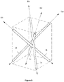
- the figure 5 represents an assembly of tubular elements according to the invention, the tubes being arranged in four distinct directions of a rectangular parallelepiped.
- the tubes of Figures 3 to 5 are represented with a substantially circular section, however, the tubes may have a section of different shape: square, rectangle, polygon, circle, ellipse ... All embodiments of the section of the tube are compatible with the various embodiments described below.
- FIG 3 illustrates a bundle of four tubes 1a to 1d, each disposed in one of four assembly directions Da to Dd.
- the four directions Da to Dd in which the tubes are assembled correspond respectively to the four diagonals of a rectangular parallelepiped, except that the tubes do not intersect at the intersection of the diagonals in the center of the rectangular parallelepiped, but meet in the neighborhood of this point.
- the construction of the ordered assembly can begin for example by repeating the layout of the figure 3 , that is to say by arranging along a construction axis XX 'presented in figure 4 , corresponding to the point of intersection of the four tubes of a beam, a new bundle of tubes 1a to 1d arranged in the same order as the previous beam, and so on.
- an ordered assembly start formed of a first row 100a of tube bundles 1a to 1d aligned along the axis.
- an interweaving of four tube networks 11 to 14 which each extend in a plane oriented along one of the four assembly directions of the tubes in a bundle.
- the tubes of each network are spaced from each other by a distance allowing the passage (crisscrossing) of the tubes of the other networks.
- the packing structure is obtained by adding an additional row of bundles along a new axis parallel to the construction axis XX '.
- the free volume is then similarly completed on either side of the row, typically to the end of the tubes of the row 100a, so as to obtain in this volume a three-dimensional structure formed of tubes arranged respectively according to four directions.
- the tubes are interconnected at the contact portions between tubes.
- the bond may be made by a chemical or mechanical process, for example, using a thermoplastic or thermosetting resin, by gluing, by carbon deposition, by welding, by mechanical hooking or other means.
- the structured packing blocks can be machined to the dimensions and shape of the contacting column.
- the contacting columns comprise a cylindrical enclosure.
- the ordered assembly of tubes is machined to obtain a packing structure which has a cylindrical shape which can be introduced into the cylindrical chamber of the column of in order to occupy a maximum of space in the column and thus to offer an optimal exchange surface.
- the structured packing blocks can be cut or machined in the form of rectangular parallelepiped blocks, the large dimension of which will be arranged when it is arranged in a contacting column, parallel to the axis of the column; ie the vertical axis.
- the arrangement of the blocks can be made in successive slices, without particular orientation of the base of the blocks from one slice to another.
- the figure 5 is an example of a rectangular parallelepiped block that can be machined for this embodiment of the invention.
- the figure 9 illustrates a nonlimiting example of arrangement of rectangular parallelepiped blocks 6 in a column 5.
- the blocks are distributed over two structured packing slices arranged one above the other.
- the section of the tubes has an elliptical shape.
- This elliptical shape of the section of the tubes makes it possible to obtain a solid arrangement of the bundles of tubes of the packing structure according to the invention (bundle of four tubes oriented along the four directions of the diagonals of a rectangular parallelepiped).
- circular section tubes are less suitable for obtaining a solid arrangement in the case of a parallelepiped structure.
- the arrangement of elliptical section tubes ensures good spacing between the tubes and ensure points of contact between the tubes.
- the geometry and dimensions of the ellipse are related to the geometry and dimensions of the rectangular parallelepiped.
- the figure 8 represents an example of an elliptical section of a tube 1 for structured packing according to the invention.
- the figure 6 represents an example of a tube 1 of polygonal section for structured packing according to the invention.
- the illustrated tube 1 is formed by a set of rings 7 of polygonal shape, here hexagonal, connected by rods 8 parallel to the axis of the tube, and corresponding generatrices of the tube. The spaces formed between the rings and the rods correspond to the orifices T of the tubes.
- the figure 7 is a view of the passage section for an elliptical section tube in an arrangement according to an embodiment according to the invention. As illustrated, the arrangement of tubes is formed of tubes of elliptical section 1 according to an embodiment very close to that described for the figure 6 . The central part of the figure 7 corresponds to a space in which a tube 1 can be inserted.
- the internal packing of the contacting column according to the present invention makes it possible to obtain excellent results in distillation operations, in particular for the manufacture of fluorinated derivatives requiring distillations in the presence of HF (hydrofluoric acid) or the distillation of certain organic acids, such as formic acid or acetic acid. It is also particularly well suited for reactive absorption applications, including post-combustion carbon dioxide capture and natural gas processing, by contacting the gas with a liquid absorbing solution.
- the structured packing blocks can be machined in the form of rectangular parallelepiped blocks. Then, the blocks are arranged in a contacting column, so that their lengths (the largest dimension) are parallel to the axis of the column, that is to say the vertical axis.
- the arrangement of the blocks can be achieved in successive slices, without particular orientation of a slice to another.
- the figure 5 is an example of a rectangular parallelepiped block that can be machined for this embodiment of the invention.
- the figure 9 illustrates a nonlimiting example of arrangement of rectangular parallelepiped blocks 6 in a column 5. For this example, the blocks are distributed over two structured packing slices arranged one above the other.
- a comparative example of the packing structure according to the invention with a packing structure according to the prior art with a scheduling of bundles of tubes according to the four directions of a cube allows to show the gains in terms of loss of loads, and therefore an increase in capacity, for the packing structure according to the invention.
- the example consists in putting a liquid, water, or a gas in contact with air, circulating in countercurrent, by means of a structured packing.
- the hydraulic diameter of the tubes is 12 mm
- the opening rate of the tubes is 50%
- the gas flow rate is constant at an absolute pressure of 1.5 bar and at a temperature of ambient
- the diameter of the column is 150 mm.
- the tubes have an elliptical section, and the angle of the tubes with respect to a vertical axis is 30 °.
- the figure 10 represents the linear pressure loss ⁇ P / m expressed in mbar / mm as a function of the kinetic factor Fs expressed in ⁇ Pa for various configurations, one with tubes inclined according to the prior art AA (patent FR 2913897 ) and the other at 30 ° according to the invention INV.
- the kinetic factor characterizes the kinetic energy of the gas in the packing. This value takes into account the effect of the pressure on the packing capacity.
- the liquid flow rate is 100 m 3 / h / m 2 .
- the capacity gain measured for this liquid flow is 50%, and the reduction in linear pressure loss is a factor of 3.
- the figure 11 is a curve identical to the curve of the figure 10 , for an example for which the liquid flow rate is 50 m 3 / h / m 2 . With this liquid flow, the variations are similar to those of the example of the figure 10 : a gain of 50% of the capacity and a reduction in linear pressure loss of a factor close to 3.5.
- the packing structure according to the invention has an increased capacity compared to the packing structure according to the prior art.
Landscapes
- Chemical & Material Sciences (AREA)
- Chemical Kinetics & Catalysis (AREA)
- Analytical Chemistry (AREA)
- Organic Chemistry (AREA)
- Engineering & Computer Science (AREA)
- Oil, Petroleum & Natural Gas (AREA)
- General Chemical & Material Sciences (AREA)
- Physics & Mathematics (AREA)
- Thermal Sciences (AREA)
- Environmental & Geological Engineering (AREA)
- Inorganic Chemistry (AREA)
- Health & Medical Sciences (AREA)
- Biomedical Technology (AREA)
- Physical Or Chemical Processes And Apparatus (AREA)
- Vaporization, Distillation, Condensation, Sublimation, And Cold Traps (AREA)
Claims (19)
- Packungsstruktur für eine Kolonne zur Kontaktierung von Fluiden, wobei die Struktur ein Volumen bildet, das eine geordnete Anordnung von Rohrbündeln (1) umfasst, wobei die Wände der Rohre Öffnungen (T, E) umfassen, die angeordnet sind, um das Zirkulieren und das Mischen der Fluide in der Struktur zu fördern, dadurch gekennzeichnet, dass jedes Bündel vier Rohre (1a, 1b, 1c, 1d) umfasst, die jeweils in den vier Richtungen ausgerichtet sind, die von den Diagonalen eines rechtwinkligen Parallelepipeds gebildet werden, wobei das rechtwinklige Parallelepiped eine Seitenabmessung umfasst, die größer ist als die anderen.
- Struktur nach Anspruch 1, wobei die größte Abmessung des rechtwinkligen Parallelepipeds in einer vertikalen Achse ausgerichtet ist.
- Struktur nach einem der vorhergehenden Ansprüche, wobei der Ausrichtungswinkel der Achse der Rohre (1) in Bezug auf eine vertikale Achse im Bereich zwischen 20 und 50°, vorzugsweise zwischen 30 und 45° liegt.
- Struktur nach einem der vorhergehenden Ansprüche, wobei der hydraulische Durchmesser (8) der Rohre (1) im Bereich zwischen 5 und 50 mm liegt.
- Struktur nach einem der vorhergehenden Ansprüche, wobei die Rohre (1) einen im Wesentlichen kreisförmigen oder elliptischen Querschnitt aufweisen.
- Struktur nach Anspruch 5, wobei der Querschnitt der Rohre (1) ein Polygon ist.
- Struktur nach einem der vorhergehenden Ansprüche, wobei die Struktur eine Vielzahl von parallelflachen Blöcken (6) aufweist, die durch die geordnete Anordnung von Rohrbündeln gebildet werden.
- Struktur nach einem der vorhergehenden Ansprüche, wobei die Öffnungen (T, E) die Form von Rechtecken aufweisen, deren Seiten zwischen 2 und 45 mm messen und wobei sich jede der Öffnungen über eine Fläche größer 2 mm2 erstreckt.
- Struktur nach einem der vorhergehenden Ansprüche, wobei das Verhältnis zwischen der Fläche der Öffnungen (T, E) und der Fläche des geschlossenen Abschnitts der Rohre (1) im Bereich zwischen 10 und 90 %, vorzugsweise zwischen 25 und 50 % liegt.
- Struktur nach einem der vorhergehenden Ansprüche, wobei die Rohre (1) ein Gewebe aus mindestens zwei Streifen (2a, 2b, 3a, 3b) umfassen, die als mindestens zwei gekreuzte Spiralen gewickelt sind, die sich entlang einer gleichen Achse erstrecken und einen gleichen Durchmesser aufweisen, wobei die Streifen (2a, 2b, 3a, 3b) voneinander beabstandet sind, um die Öffnungen (E) zu bilden.
- Struktur nach einem der vorhergehenden Ansprüche, wobei die Rohre (1) aus einer Vielzahl von Ringen (7) gebildet werden, die durch mindestens eine Stange (8) verbunden sind, wobei die Stange (8) entlang einer Mantellinie des Rohrs (1) angeordnet ist.
- Struktur nach einem der vorhergehenden Ansprüche, wobei die Rohre (1) aus einem Material hergestellt sind, ausgewählt aus Kohlenstoff, der durch Ablagerung von Kohlenstoff verfestigt ist, einem Metall, einer Keramik, einem Polymermaterial, einem thermoplastischen Material, einem duroplastischen Material.
- Kolonne zur Kontaktierung von Fluiden (5) umfassend eine Packung, dadurch gekennzeichnet, dass die Packung eine Packungsstruktur nach einem der vorhergehenden Ansprüche umfasst.
- Verwendung einer Kolonne zur Kontaktierung von Fluiden (5) nach Anspruch 13 in einem Destillationsverfahren, einem Verfahren zur reaktiven Absorption, wie beispielsweise der Abscheidung von Sauergasen und der Behandlung von Erdgas.
- Verfahren zur Herstellung einer Packungsstruktur einer Kolonne zur Kontaktierung von Fluiden, wobei die folgenden Schritte durchgeführt werden:a) Herstellen der Rohre (1), die die Öffnungen (T, E) umfassen, die angeordnet sind, um das Zirkulieren und das Mischen der Fluide in der Struktur zu fördern;b) Konstruieren einer geordneten Anordnung der Rohre (1), indem Rohrbündel nebeneinander angeordnet werden, wobei die Rohrbündel vier Rohre (1a, 1b, 1c, 1d) umfassen, die jeweils in den vier Richtungen ausgerichtet sind, die von den Diagonalen eines rechtwinkligen Parallelepipeds gebildet werden, wobei das rechtwinklige Parallelepiped eine Abmessung umfasst, die größer ist als die anderen; undc) Verbinden der Rohre (1) an ihrem Kontaktabschnitt.
- Verfahren nach Anspruch 15, wobei in Schritt a) Rohre (1) mit kreisförmigem oder elliptischem Querschnitt hergestellt werden.
- Verfahren nach Anspruch 16, wobei der Querschnitt der Rohre (1) ein Polygon ist.
- Verfahren nach einem der vorhergehenden Ansprüche 15 bis 17, wobei die größte Abmessung des rechtwinkligen Parallelepipeds entlang einer vertikalen Achse ausgerichtet wird.
- Verfahren nach einem der vorhergehenden Ansprüche 15 bis 18, wobei das Verfahren einen Schritt zum Bearbeiten der geordneten Anordnung umfasst, um rechtwinklige Parallelepipedblöcke (6) zu bilden, und einen Schritt zur Anordnung der Blöcke (6) in der Kolonne (5).
Applications Claiming Priority (1)
| Application Number | Priority Date | Filing Date | Title |
|---|---|---|---|
| FR1558652A FR3040894A1 (fr) | 2015-09-15 | 2015-09-15 | Structure de garnissage optimisee pour colonne de mise en contact de fluides et procede de fabrication |
Publications (2)
| Publication Number | Publication Date |
|---|---|
| EP3144060A1 EP3144060A1 (de) | 2017-03-22 |
| EP3144060B1 true EP3144060B1 (de) | 2018-06-13 |
Family
ID=55646660
Family Applications (1)
| Application Number | Title | Priority Date | Filing Date |
|---|---|---|---|
| EP16188390.5A Not-in-force EP3144060B1 (de) | 2015-09-15 | 2016-09-12 | Struktur für optimierte auskleidung für eine flüssigkeitskontaktsäule, und herstellungsverfahren |
Country Status (4)
| Country | Link |
|---|---|
| US (1) | US20170072380A1 (de) |
| EP (1) | EP3144060B1 (de) |
| CN (1) | CN106512914A (de) |
| FR (1) | FR3040894A1 (de) |
Families Citing this family (1)
| Publication number | Priority date | Publication date | Assignee | Title |
|---|---|---|---|---|
| WO2019135139A1 (en) * | 2018-01-08 | 2019-07-11 | Koch-Glitsch, Lp | Structured packing module for use in a mass transfer column and method of assembly |
Family Cites Families (8)
| Publication number | Priority date | Publication date | Assignee | Title |
|---|---|---|---|---|
| DE4009885A1 (de) | 1990-03-28 | 1991-10-02 | Goldau Rudi Gmbh | Bodenbelag |
| DE4104447A1 (de) | 1991-02-14 | 1992-08-20 | Sigri Gmbh | Korrosions- und hitzebestaendige geordnete packung fuer stoff- und waermeaustauschprozesse |
| US5901575A (en) * | 1997-08-25 | 1999-05-11 | Air Products And Chemicals, Inc. | Stackable structured packing with controlled symmetry |
| DE10005457A1 (de) * | 2000-02-08 | 2001-08-09 | Bayer Ag | Statischer Mischer |
| FR2892644B1 (fr) * | 2005-10-28 | 2008-02-08 | Snecma Propulsion Solide Sa | Structure de garnissage pour colonne d'echange de fluides |
| CN101190406A (zh) * | 2006-11-29 | 2008-06-04 | Snecma固体燃料推进器公司 | 用于流体交换柱的填充结构 |
| FR2913897B1 (fr) * | 2007-03-20 | 2009-11-20 | Inst Francais Du Petrole | Structure de garnissage pour colonne de mise en contact de fluides et methode de fabrication. |
| CN104587945A (zh) * | 2015-01-24 | 2015-05-06 | 福州大学 | 一种催化精馏塔塔内规整催化填料及其制备方法 |
-
2015
- 2015-09-15 FR FR1558652A patent/FR3040894A1/fr not_active Ceased
-
2016
- 2016-09-12 EP EP16188390.5A patent/EP3144060B1/de not_active Not-in-force
- 2016-09-14 US US15/265,578 patent/US20170072380A1/en not_active Abandoned
- 2016-09-18 CN CN201610826738.2A patent/CN106512914A/zh active Pending
Non-Patent Citations (1)
| Title |
|---|
| None * |
Also Published As
| Publication number | Publication date |
|---|---|
| CN106512914A (zh) | 2017-03-22 |
| FR3040894A1 (fr) | 2017-03-17 |
| EP3144060A1 (de) | 2017-03-22 |
| US20170072380A1 (en) | 2017-03-16 |
Similar Documents
| Publication | Publication Date | Title |
|---|---|---|
| EP2129459B1 (de) | Packungsstruktur für eine flüssigkeitskontaktsäule und verfahren zu ihrer herstellung | |
| EP2134463B2 (de) | Strukturierte hochleistungsverpackung für eine säule mit flüssigkeitskontakt und verfahren zu ihrer herstellung | |
| RU2418255C1 (ru) | Блок насадки градирни | |
| EP3144060B1 (de) | Struktur für optimierte auskleidung für eine flüssigkeitskontaktsäule, und herstellungsverfahren | |
| FR2865027A1 (fr) | Ailette pour echangeur de chaleur et echangeur de chaleur muni de telles ailettes | |
| EP3132222B1 (de) | Wärmeaustauschermodul, verwendung mit flüssigmetall und gas | |
| EP3728976A1 (de) | Abstandselement mit oberflächentexturierung sowie zugehöriger wärmetauscher und herstellungsverfahren | |
| FR2918399A1 (fr) | Coffrage a elements internes filtrants pour realiser un voile en beton de grande epaisseur | |
| EP4086556A1 (de) | Plattenwärmetauschermodul mit kanälen, das mindestens einen durch noppen gebildeten bereich für die zufuhr und verteilung von fluiden umfasst | |
| EP2126927B1 (de) | Abstandhaltergitter mit sattelförmigen stützelementen und hiermit versehenes kerbrennstabbündel | |
| CH697571B1 (fr) | Structure de garnissage pour colonne d'échange de fluides. | |
| EP0117829A1 (de) | Rohrbündelwärmetauscher | |
| FR3113610A1 (fr) | Garnissage filaire pour un appareil d’echange de matiere | |
| BE660070A (de) | ||
| WO2018104124A1 (fr) | Procede de fabrication d'un garnissage structure par une methode de fabrication additive | |
| EP2722615B1 (de) | Röhrenverdampfer und Verfahren zum Herstellen eines Röhrenverdampfers | |
| FR3140420A1 (fr) | Echangeur de chaleur à structure d’échange thermique améliorée | |
| RU2477433C1 (ru) | Ороситель градирни | |
| FR2996148A1 (fr) | Element de garnissage structure pour colonne de mise en contact de fluides | |
| FR3075335B1 (fr) | Echangeur de chaleur avec elements intercalaires superposes | |
| FR2889582A1 (fr) | Echangeur tubulaire de chaleur | |
| FR3075337A1 (fr) | Element intercalaire a texturation de surface, echangeur de chaleur comprenant un tel element | |
| FR2641066A1 (en) | Improvement to fluid condenser tubes with longitudinal fins and condensers using such tubes | |
| EP1455206A1 (de) | Verfahren zur Herstellung einer photo-kristallinen Plastikfaser | |
| FR3165061A1 (fr) | Insert rotatif pour tube d’echangeur de chaleur |
Legal Events
| Date | Code | Title | Description |
|---|---|---|---|
| PUAI | Public reference made under article 153(3) epc to a published international application that has entered the european phase |
Free format text: ORIGINAL CODE: 0009012 |
|
| AK | Designated contracting states |
Kind code of ref document: A1 Designated state(s): AL AT BE BG CH CY CZ DE DK EE ES FI FR GB GR HR HU IE IS IT LI LT LU LV MC MK MT NL NO PL PT RO RS SE SI SK SM TR |
|
| AX | Request for extension of the european patent |
Extension state: BA ME |
|
| 17P | Request for examination filed |
Effective date: 20170922 |
|
| RAP1 | Party data changed (applicant data changed or rights of an application transferred) |
Owner name: IFP ENERGIES NOUVELLES Owner name: HERAKLES |
|
| RBV | Designated contracting states (corrected) |
Designated state(s): AL AT BE BG CH CY CZ DE DK EE ES FI FR GB GR HR HU IE IS IT LI LT LU LV MC MK MT NL NO PL PT RO RS SE SI SK SM TR |
|
| RIC1 | Information provided on ipc code assigned before grant |
Ipc: B01D 3/26 20060101ALI20171011BHEP Ipc: B01J 19/02 20060101ALN20171011BHEP Ipc: B01D 53/18 20060101ALN20171011BHEP Ipc: B01J 19/32 20060101AFI20171011BHEP |
|
| GRAP | Despatch of communication of intention to grant a patent |
Free format text: ORIGINAL CODE: EPIDOSNIGR1 |
|
| INTG | Intention to grant announced |
Effective date: 20180102 |
|
| RAP1 | Party data changed (applicant data changed or rights of an application transferred) |
Owner name: LACOMBE, ALAIN Owner name: IFP ENERGIES NOUVELLES |
|
| GRAS | Grant fee paid |
Free format text: ORIGINAL CODE: EPIDOSNIGR3 |
|
| GRAA | (expected) grant |
Free format text: ORIGINAL CODE: 0009210 |
|
| AK | Designated contracting states |
Kind code of ref document: B1 Designated state(s): AL AT BE BG CH CY CZ DE DK EE ES FI FR GB GR HR HU IE IS IT LI LT LU LV MC MK MT NL NO PL PT RO RS SE SI SK SM TR |
|
| REG | Reference to a national code |
Ref country code: GB Ref legal event code: FG4D Free format text: NOT ENGLISH |
|
| REG | Reference to a national code |
Ref country code: CH Ref legal event code: EP Ref country code: AT Ref legal event code: REF Ref document number: 1007901 Country of ref document: AT Kind code of ref document: T Effective date: 20180615 |
|
| REG | Reference to a national code |
Ref country code: IE Ref legal event code: FG4D Free format text: LANGUAGE OF EP DOCUMENT: FRENCH |
|
| REG | Reference to a national code |
Ref country code: DE Ref legal event code: R096 Ref document number: 602016003541 Country of ref document: DE |
|
| REG | Reference to a national code |
Ref country code: FR Ref legal event code: PLFP Year of fee payment: 3 |
|
| REG | Reference to a national code |
Ref country code: NL Ref legal event code: MP Effective date: 20180613 |
|
| REG | Reference to a national code |
Ref country code: LT Ref legal event code: MG4D |
|
| REG | Reference to a national code |
Ref country code: NO Ref legal event code: T2 Effective date: 20180613 |
|
| PG25 | Lapsed in a contracting state [announced via postgrant information from national office to epo] |
Ref country code: FI Free format text: LAPSE BECAUSE OF FAILURE TO SUBMIT A TRANSLATION OF THE DESCRIPTION OR TO PAY THE FEE WITHIN THE PRESCRIBED TIME-LIMIT Effective date: 20180613 Ref country code: CY Free format text: LAPSE BECAUSE OF FAILURE TO SUBMIT A TRANSLATION OF THE DESCRIPTION OR TO PAY THE FEE WITHIN THE PRESCRIBED TIME-LIMIT Effective date: 20180613 Ref country code: LT Free format text: LAPSE BECAUSE OF FAILURE TO SUBMIT A TRANSLATION OF THE DESCRIPTION OR TO PAY THE FEE WITHIN THE PRESCRIBED TIME-LIMIT Effective date: 20180613 Ref country code: ES Free format text: LAPSE BECAUSE OF FAILURE TO SUBMIT A TRANSLATION OF THE DESCRIPTION OR TO PAY THE FEE WITHIN THE PRESCRIBED TIME-LIMIT Effective date: 20180613 Ref country code: SE Free format text: LAPSE BECAUSE OF FAILURE TO SUBMIT A TRANSLATION OF THE DESCRIPTION OR TO PAY THE FEE WITHIN THE PRESCRIBED TIME-LIMIT Effective date: 20180613 Ref country code: BG Free format text: LAPSE BECAUSE OF FAILURE TO SUBMIT A TRANSLATION OF THE DESCRIPTION OR TO PAY THE FEE WITHIN THE PRESCRIBED TIME-LIMIT Effective date: 20180913 |
|
| PG25 | Lapsed in a contracting state [announced via postgrant information from national office to epo] |
Ref country code: LV Free format text: LAPSE BECAUSE OF FAILURE TO SUBMIT A TRANSLATION OF THE DESCRIPTION OR TO PAY THE FEE WITHIN THE PRESCRIBED TIME-LIMIT Effective date: 20180613 Ref country code: RS Free format text: LAPSE BECAUSE OF FAILURE TO SUBMIT A TRANSLATION OF THE DESCRIPTION OR TO PAY THE FEE WITHIN THE PRESCRIBED TIME-LIMIT Effective date: 20180613 Ref country code: GR Free format text: LAPSE BECAUSE OF FAILURE TO SUBMIT A TRANSLATION OF THE DESCRIPTION OR TO PAY THE FEE WITHIN THE PRESCRIBED TIME-LIMIT Effective date: 20180914 Ref country code: HR Free format text: LAPSE BECAUSE OF FAILURE TO SUBMIT A TRANSLATION OF THE DESCRIPTION OR TO PAY THE FEE WITHIN THE PRESCRIBED TIME-LIMIT Effective date: 20180613 |
|
| REG | Reference to a national code |
Ref country code: AT Ref legal event code: MK05 Ref document number: 1007901 Country of ref document: AT Kind code of ref document: T Effective date: 20180613 |
|
| PG25 | Lapsed in a contracting state [announced via postgrant information from national office to epo] |
Ref country code: NL Free format text: LAPSE BECAUSE OF FAILURE TO SUBMIT A TRANSLATION OF THE DESCRIPTION OR TO PAY THE FEE WITHIN THE PRESCRIBED TIME-LIMIT Effective date: 20180613 |
|
| PG25 | Lapsed in a contracting state [announced via postgrant information from national office to epo] |
Ref country code: IS Free format text: LAPSE BECAUSE OF FAILURE TO SUBMIT A TRANSLATION OF THE DESCRIPTION OR TO PAY THE FEE WITHIN THE PRESCRIBED TIME-LIMIT Effective date: 20181013 Ref country code: EE Free format text: LAPSE BECAUSE OF FAILURE TO SUBMIT A TRANSLATION OF THE DESCRIPTION OR TO PAY THE FEE WITHIN THE PRESCRIBED TIME-LIMIT Effective date: 20180613 Ref country code: AT Free format text: LAPSE BECAUSE OF FAILURE TO SUBMIT A TRANSLATION OF THE DESCRIPTION OR TO PAY THE FEE WITHIN THE PRESCRIBED TIME-LIMIT Effective date: 20180613 Ref country code: PL Free format text: LAPSE BECAUSE OF FAILURE TO SUBMIT A TRANSLATION OF THE DESCRIPTION OR TO PAY THE FEE WITHIN THE PRESCRIBED TIME-LIMIT Effective date: 20180613 Ref country code: SK Free format text: LAPSE BECAUSE OF FAILURE TO SUBMIT A TRANSLATION OF THE DESCRIPTION OR TO PAY THE FEE WITHIN THE PRESCRIBED TIME-LIMIT Effective date: 20180613 Ref country code: CZ Free format text: LAPSE BECAUSE OF FAILURE TO SUBMIT A TRANSLATION OF THE DESCRIPTION OR TO PAY THE FEE WITHIN THE PRESCRIBED TIME-LIMIT Effective date: 20180613 Ref country code: RO Free format text: LAPSE BECAUSE OF FAILURE TO SUBMIT A TRANSLATION OF THE DESCRIPTION OR TO PAY THE FEE WITHIN THE PRESCRIBED TIME-LIMIT Effective date: 20180613 |
|
| PGFP | Annual fee paid to national office [announced via postgrant information from national office to epo] |
Ref country code: PL Payment date: 20180810 Year of fee payment: 3 |
|
| PG25 | Lapsed in a contracting state [announced via postgrant information from national office to epo] |
Ref country code: IT Free format text: LAPSE BECAUSE OF FAILURE TO SUBMIT A TRANSLATION OF THE DESCRIPTION OR TO PAY THE FEE WITHIN THE PRESCRIBED TIME-LIMIT Effective date: 20180613 Ref country code: SM Free format text: LAPSE BECAUSE OF FAILURE TO SUBMIT A TRANSLATION OF THE DESCRIPTION OR TO PAY THE FEE WITHIN THE PRESCRIBED TIME-LIMIT Effective date: 20180613 |
|
| REG | Reference to a national code |
Ref country code: DE Ref legal event code: R097 Ref document number: 602016003541 Country of ref document: DE |
|
| PLBE | No opposition filed within time limit |
Free format text: ORIGINAL CODE: 0009261 |
|
| STAA | Information on the status of an ep patent application or granted ep patent |
Free format text: STATUS: NO OPPOSITION FILED WITHIN TIME LIMIT |
|
| PG25 | Lapsed in a contracting state [announced via postgrant information from national office to epo] |
Ref country code: MC Free format text: LAPSE BECAUSE OF FAILURE TO SUBMIT A TRANSLATION OF THE DESCRIPTION OR TO PAY THE FEE WITHIN THE PRESCRIBED TIME-LIMIT Effective date: 20180613 |
|
| 26N | No opposition filed |
Effective date: 20190314 |
|
| PG25 | Lapsed in a contracting state [announced via postgrant information from national office to epo] |
Ref country code: DK Free format text: LAPSE BECAUSE OF FAILURE TO SUBMIT A TRANSLATION OF THE DESCRIPTION OR TO PAY THE FEE WITHIN THE PRESCRIBED TIME-LIMIT Effective date: 20180613 Ref country code: SI Free format text: LAPSE BECAUSE OF FAILURE TO SUBMIT A TRANSLATION OF THE DESCRIPTION OR TO PAY THE FEE WITHIN THE PRESCRIBED TIME-LIMIT Effective date: 20180613 |
|
| REG | Reference to a national code |
Ref country code: BE Ref legal event code: MM Effective date: 20180930 |
|
| REG | Reference to a national code |
Ref country code: IE Ref legal event code: MM4A |
|
| PG25 | Lapsed in a contracting state [announced via postgrant information from national office to epo] |
Ref country code: LU Free format text: LAPSE BECAUSE OF NON-PAYMENT OF DUE FEES Effective date: 20180912 |
|
| PG25 | Lapsed in a contracting state [announced via postgrant information from national office to epo] |
Ref country code: IE Free format text: LAPSE BECAUSE OF NON-PAYMENT OF DUE FEES Effective date: 20180912 |
|
| PG25 | Lapsed in a contracting state [announced via postgrant information from national office to epo] |
Ref country code: BE Free format text: LAPSE BECAUSE OF NON-PAYMENT OF DUE FEES Effective date: 20180930 |
|
| PGFP | Annual fee paid to national office [announced via postgrant information from national office to epo] |
Ref country code: FR Payment date: 20190925 Year of fee payment: 4 |
|
| PG25 | Lapsed in a contracting state [announced via postgrant information from national office to epo] |
Ref country code: AL Free format text: LAPSE BECAUSE OF FAILURE TO SUBMIT A TRANSLATION OF THE DESCRIPTION OR TO PAY THE FEE WITHIN THE PRESCRIBED TIME-LIMIT Effective date: 20180613 |
|
| PG25 | Lapsed in a contracting state [announced via postgrant information from national office to epo] |
Ref country code: MT Free format text: LAPSE BECAUSE OF FAILURE TO SUBMIT A TRANSLATION OF THE DESCRIPTION OR TO PAY THE FEE WITHIN THE PRESCRIBED TIME-LIMIT Effective date: 20180613 |
|
| PGFP | Annual fee paid to national office [announced via postgrant information from national office to epo] |
Ref country code: DE Payment date: 20191129 Year of fee payment: 4 Ref country code: CH Payment date: 20190925 Year of fee payment: 4 |
|
| PG25 | Lapsed in a contracting state [announced via postgrant information from national office to epo] |
Ref country code: TR Free format text: LAPSE BECAUSE OF FAILURE TO SUBMIT A TRANSLATION OF THE DESCRIPTION OR TO PAY THE FEE WITHIN THE PRESCRIBED TIME-LIMIT Effective date: 20180613 |
|
| REG | Reference to a national code |
Ref country code: NO Ref legal event code: MMEP |
|
| PG25 | Lapsed in a contracting state [announced via postgrant information from national office to epo] |
Ref country code: PT Free format text: LAPSE BECAUSE OF FAILURE TO SUBMIT A TRANSLATION OF THE DESCRIPTION OR TO PAY THE FEE WITHIN THE PRESCRIBED TIME-LIMIT Effective date: 20180613 |
|
| PG25 | Lapsed in a contracting state [announced via postgrant information from national office to epo] |
Ref country code: MK Free format text: LAPSE BECAUSE OF NON-PAYMENT OF DUE FEES Effective date: 20180613 Ref country code: HU Free format text: LAPSE BECAUSE OF FAILURE TO SUBMIT A TRANSLATION OF THE DESCRIPTION OR TO PAY THE FEE WITHIN THE PRESCRIBED TIME-LIMIT; INVALID AB INITIO Effective date: 20160912 |
|
| PG25 | Lapsed in a contracting state [announced via postgrant information from national office to epo] |
Ref country code: NO Free format text: LAPSE BECAUSE OF NON-PAYMENT OF DUE FEES Effective date: 20190930 |
|
| REG | Reference to a national code |
Ref country code: DE Ref legal event code: R119 Ref document number: 602016003541 Country of ref document: DE |
|
| REG | Reference to a national code |
Ref country code: CH Ref legal event code: PL |
|
| GBPC | Gb: european patent ceased through non-payment of renewal fee |
Effective date: 20200912 |
|
| PG25 | Lapsed in a contracting state [announced via postgrant information from national office to epo] |
Ref country code: FR Free format text: LAPSE BECAUSE OF NON-PAYMENT OF DUE FEES Effective date: 20200930 Ref country code: DE Free format text: LAPSE BECAUSE OF NON-PAYMENT OF DUE FEES Effective date: 20210401 |
|
| PG25 | Lapsed in a contracting state [announced via postgrant information from national office to epo] |
Ref country code: LI Free format text: LAPSE BECAUSE OF NON-PAYMENT OF DUE FEES Effective date: 20200930 Ref country code: GB Free format text: LAPSE BECAUSE OF NON-PAYMENT OF DUE FEES Effective date: 20200912 Ref country code: CH Free format text: LAPSE BECAUSE OF NON-PAYMENT OF DUE FEES Effective date: 20200930 |