EP2135023B1 - Sécheur centrifuge - Google Patents
Sécheur centrifuge Download PDFInfo
- Publication number
- EP2135023B1 EP2135023B1 EP08716616A EP08716616A EP2135023B1 EP 2135023 B1 EP2135023 B1 EP 2135023B1 EP 08716616 A EP08716616 A EP 08716616A EP 08716616 A EP08716616 A EP 08716616A EP 2135023 B1 EP2135023 B1 EP 2135023B1
- Authority
- EP
- European Patent Office
- Prior art keywords
- screen
- elements
- sieve
- accordance
- centrifugal dryer
- Prior art date
- Legal status (The legal status is an assumption and is not a legal conclusion. Google has not performed a legal analysis and makes no representation as to the accuracy of the status listed.)
- Active
Links
Images


Classifications
-
- F—MECHANICAL ENGINEERING; LIGHTING; HEATING; WEAPONS; BLASTING
- F26—DRYING
- F26B—DRYING SOLID MATERIALS OR OBJECTS BY REMOVING LIQUID THEREFROM
- F26B5/00—Drying solid materials or objects by processes not involving the application of heat
- F26B5/08—Drying solid materials or objects by processes not involving the application of heat by centrifugal treatment
-
- B—PERFORMING OPERATIONS; TRANSPORTING
- B04—CENTRIFUGAL APPARATUS OR MACHINES FOR CARRYING-OUT PHYSICAL OR CHEMICAL PROCESSES
- B04B—CENTRIFUGES
- B04B5/00—Other centrifuges
- B04B5/12—Centrifuges in which rotors other than bowls generate centrifugal effects in stationary containers
-
- B—PERFORMING OPERATIONS; TRANSPORTING
- B04—CENTRIFUGAL APPARATUS OR MACHINES FOR CARRYING-OUT PHYSICAL OR CHEMICAL PROCESSES
- B04B—CENTRIFUGES
- B04B7/00—Elements of centrifuges
- B04B7/08—Rotary bowls
- B04B7/12—Inserts, e.g. armouring plates
- B04B7/16—Sieves or filters
-
- F—MECHANICAL ENGINEERING; LIGHTING; HEATING; WEAPONS; BLASTING
- F26—DRYING
- F26B—DRYING SOLID MATERIALS OR OBJECTS BY REMOVING LIQUID THEREFROM
- F26B17/00—Machines or apparatus for drying materials in loose, plastic, or fluidised form, e.g. granules, staple fibres, with progressive movement
- F26B17/24—Machines or apparatus for drying materials in loose, plastic, or fluidised form, e.g. granules, staple fibres, with progressive movement with movement performed by shooting or throwing the materials, e.g. after which the materials are subject to impact
Definitions
- the present invention relates to a centrifugal dryer for separating granular substances from a fluid, comprising a housing, a rotor arranged in the housing and a sieve surrounding the rotor, the sieve having at least one porous sieve element forming at least one sector of the lateral surfaces and arcuate is placed around at least one Siebango Vietnamese and releasably secured thereto, and wherein the sieve is connectable to a circumferentially arranged connection body, in the region of which the sieve has a circumferential recess in which no sieve element is arranged.
- Plastic pellets which are produced by underwater granulation are continuously separated by the underwater granulator downstream centrifugal dryer from the process water of the granulator.
- Such centrifugal dryers which may possibly also be used for separating other granular substances from a corresponding fluid, usually have an upright rotor, which is rotationally driven about an upright rotor axis and by means of mostly scoop-shaped conveying elements, the granules or the granulated water Promotes mixture from bottom to top, wherein the mixture is thrown radially outward.
- the pellets are retained by the sieve surrounding the rotor, while the water or the corresponding fluid can pass through the porous sieve elements and drain outside of the sieve.
- a centrifugal dryer is known, the rotor is circumferentially surrounded by a sieve which is formed by a porous sieve, which is placed around a Siebangosammlung and screwed by means of a screw bolt.
- a hopper communicates with the rotor space via a recess in the screen and allows the pellets to be dried onto the rotor.
- Such screen constructions are capable of improvement in various respects.
- they are relatively expensive to manufacture, since when welding the holding elements to the sieve element edges, care must be taken that the sieve elements themselves do not warp. If there is still welding distortion, leakage problems occur.
- the sieve elements can only be rolled forward with difficulty, in particular if quite stiff sieve elements have to be used for corresponding applications. The assembly and disassembly of the sieve elements is thereby made correspondingly difficult.
- the present invention is based on the object to provide an improved centrifugal dryer of the type mentioned, which avoids the disadvantages of the prior art and further develops the latter in an advantageous manner.
- a cost-to-manufacture sieve for such a centrifugal dryer is to be created, which is easy to assemble and disassemble, without creating leakage problems and granular leakage, and is variably adaptable to different terminal configurations.
- the hitherto adopted path is left to attach to the Siebelementer selectedn, which adjoin each other in the rolled state, own fastening or holding elements, which initiate the train in the sieve elements when clamping each other.
- the screen is composed of a plurality of screen elements which overlap each other in the circumferential direction, or a screen element with circumferentially overlapping Siebelementenden and tightened by one or more straps that wrap around the overlapping screen elements circumferentially on the Siebango Vietnamese.
- a tension belt basically differently shaped, pliable, flexible and / or bending elastic tension elements can be wrapped around screening elements, which are stretched and thereby hold the screen elements together and in particular pull on Sieb lake arranged inside filter carrier.
- the Siebelementbefest only by such straps is characterized by a simple manufacturability and a high density and freedom from leaks.
- no heat deformations of the sieve elements which occur, for example, during the welding of holding pieces occur, so that a substantial freedom from leaks can be achieved in a simple manner.
- sieves of different diameters or different connection options can be configured by means of sieve elements configured as standard since, for example, an additional sieve element is simply placed on the sieve tire or the overlap offset is made smaller in order to produce a larger sieve diameter.
- the overlapping Sieve elements are shifted in the circumferential direction to each other, so that a connection gap is formed. All this is also subsequently changed, since the sieve elements are not firmly connected to holding elements or welded to frame profiles, but are merely clamped by friction fluid through the tension straps on the screen tire.
- the sieve elements themselves may be formed free of fastening and holding elements.
- the retaining pieces usually otherwise welded to the screen element edges need no longer be provided.
- the sieve elements are held together exclusively by the tension straps. It does not need to be welded or otherwise fixed to the axial longitudinal edges of the screen elements.
- the susceptible to leakage problems Siebissekanten be individually superimposed overlapping each other and held each other by the straps, the superimposed Sieb comprisekanten retain their elasticity for lack of welded holding pieces and slit and slot-free can lie on top of each other.
- the sieve elements do not need to be completely free of weld seams. In order to avoid the aforementioned leakage problems due to thermal distortion, it may be sufficient to form the Siebierikanten or edges without welding.
- the tension straps can, in the case of suitable, in particular metallic, training by means of spot welds on the sieve elements be attached to allow easier handling and to avoid slippage, so that a precise fit, proper installation without slipping the straps can accomplish easier.
- approximately sieve elements can be attached in the middle of the respective tension straps by one or more welds.
- the tension straps may also be attached or connected to the strainer elements in another manner, for example by adhesive bonding.
- the complementary circumferentially screening elements can be formed in this case of different sizes and / or different degrees, for example, can cover a sector of 3/2 ⁇ , and a second screen element remaining sector of 1 ⁇ 2 ⁇ a first Siebieri counseling, it being understood would be added to the corresponding overlap.
- the sieve elements can be slid in the circumferential direction to each other, whereby the width of the overlap changed and, if necessary, can be changed by inserting another SiebNeills the screen diameter.
- the sieve can also be composed of a plurality of sieve elements viewed in the axial direction, in which case the plurality of sieve elements are advantageously connected and held together solely by tension straps.
- a plurality of Siebangoographie are provided on which the sieve elements are stretched by means of the tension straps, wherein preferably such a Siebango adopted is provided in particular in the region of the axial interface between two sieve sections.
- each axial screen section advantageously has at least two screen carrier tires which are preferably arranged at the end-side end sections of the respective screen section, wherein a common screen carrier strip may be provided for both screen sections preferably at an axial interface between two screen sections.
- the axially adjacent sieve elements can be attached to the said common Siebangosammlung in fundamentally different ways.
- the sieve elements on the Siebangosammlung can overlap each other axially and be tightened by a common, arranged in the axial overlap region tension belt.
- the common Siebyes Vietnamese may also have a radial Trendsteg that divides the common Sieby Vietnamese into two circumferential Aufspannabitese.
- the sieve elements can be aligned axially against the said trend bar in the manner of a stop and then be tightened by a separate strap on the common Siebangoatty.
- connection bodies for example in the form of an inlet shaft, an outlet shaft or another connection piece, can be connected to the screen on the circumference, wherein the screen or the porous screen element has a circumferential recess in the area of this connection body having.
- connection bodies are often provided in the region of a lower or upper end section of the sieve, for example in order to introduce the granulate / fluid mixture into the rotor section.
- the leakage problems described at the outset occur with pleasure.
- the sieve assembly and disassembly is often complicated and complicated, especially in these areas.
- the corresponding sieve element is also fastened in the area of such peripheral connection body by at least one tensioning belt, wherein the tensioning belt simultaneously holds the connection body on the sieve.
- the tension straps in the region of such a connecting body thus advantageously fulfill a dual function in that on the one hand connect the strainer and connection body and on the other hand fix the sieve element or the sieve elements in this section of the sieve in the aforementioned manner by wrapping and sealing together.
- articulation points for at least one tensioning belt are provided on the connection body, so that the respective tensioning belt can be struck peripherally on the two sides of the connection body.
- a terminal strip is provided here, which is advantageously releasably and hingedly fastened to the connector body and on the other hand has articulation points for the at least one tension belt, so that the tension belt can be hit on the terminal block.
- the terminal strip here by means of hinge pins can be detachably attached to the connector body, so that the terminal strip on the one hand easily by axially pulling the hinge pin and / or removing the terminal block itself from the connector body is solvable and on the other hand about a hinge joint axis parallel to the longitudinal axis of the Sieves can hinge relative to the connector body, which can be clamped by tightening the strapped thereto straps pushed under or over the terminal block sieve.
- the said terminal strip together with an edge web of the connecting piece form a slot-shaped receiving mouth into which the sieve element can be inserted at the edge. If the tension straps attached to the terminal strip are tightened, the jaw closes, as it were, and the terminal strip is pulled onto the edge web of the connecting piece, whereby the sieve element is securely fixed.
- the tension straps advantageously each associated with a tool-free operable clamping means, which allows to relax the straps by hand.
- a skischuhschnallen shamer quick-release lever may be provided which can be fastened at one end of the respective tensioning belt and at the opposite end of the tensioning belt, in particular by means of a trailer can be suspended.
- Particularly advantageous may be the screen assembly from each other in the circumferential direction overlapping sieve elements for rotating screens, in which the rotor mentioned above is rotatably received.
- rotary screens which rotate themselves and possibly rotate at high speeds in a liquid bath
- Siebüberlappungs Symposiume was preferred by flush joining butting by means of suitable frame profiles in order to avoid overlaps induced by the turbulence, play in contrast to standing sieves such overlap edges irrelevant.
- a rotor 4 is arranged, which can be driven in rotation about an upright pivot axis by means of a drive motor not shown in detail.
- the rotor 4 comprises a plurality of blade-like conveying elements 5, which are arranged cantilevered from the central rotor axis and conveyed into the centrifugal dryer 1 granulated / process water mixture in the interior 3 of the housing 2 from bottom to top.
- the projecting from the rotor axis conveying elements 5 can in principle be designed differently, for example in the form of planar, curved or curved plates or in the form of helically curved elements or otherwise shaped conveying members.
- the rotor 4 is surrounded in the interior 3 by an overall cylindrical sieve 6, which surrounds the rotor 4 such that granules hurled by the rotor 4 during conveyance are retained in the interior space enclosed by the sieve 6, while process water passes through the Sieve 6 pass and can run in the gap between the sieve 6 and housing 2 down.
- connection body 7 in the form of an inlet shaft 8 is connected at a lower screen section 6a mantle surface side to the screen 6, through which the granules / fluid mixture through the screen 6 on the rotor 4 can be gebbar.
- the inlet shaft 8 can be connected, for example, to an underwater pelletizer which generates the plastic pellets and introduces the resulting granulate / fluid mixture into the centrifugal drier 1.
- the sieve 6 is composed of a plurality of sieve elements 10, each of elastic, in the initial state, flat or slightly bulging, in particular pre-rolled or otherwise suitably bent, porous screen plates or plates and have been brought into the arcuate or cylindrical shape shown in the figures. More precisely, the sieve elements 10 form cylinder jacket surface segments in each case, since the sieve 6, viewed in the circumferential direction, is composed of a plurality of sieve elements 10a, 10b, 10c ... which overlap one another and together form a sieve ring.
- the screen 6 is not only composed in the circumferential direction of several sieve elements 10, but also considered in the axial direction.
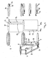
- the Figures 2 and 3 show two separate in the axial direction sieve sections 6a and 6b, which are each formed by a plurality of sieve elements 10, wherein in the illustrated embodiment, the lower sieve section 6a consists of two sieve elements 10, while the upper sieve section 6b of three sieve elements 10 is composed.
- the sieve elements 10 are in each case wound around Siebyographie 11 at their end-side end portions, wherein between the two sieve sections 6a and 6b, a common Siebyographie 11 is provided for both sieve sections 6a and 6b, see. also FIG. 4 ,
- the lower Siebysammlung 11 of the lower wire section 6a is simultaneously formed as a sieve bottom, see. FIG. 4 ,
- the upper screen section 6b is completely cylindrical, i. the sieve elements 10 enclose the entire lateral surface of the sieve section 6b, with the plurality of sieve elements 10 overlapping one another at their axial edges.
- the sieve elements 10 are formed at their adjacent axial edges or edges 13, which form the respective overlap regions 12, free of holding pieces or connecting elements. They lie only on each other through the overlap region 12, wherein optionally a sealing element, for example in the form of a band, can be interposed therebetween.
- the sieve elements 10 held together and fastened are the sieve elements 10 by tension straps or bands 14, which may be formed by differently shaped tension elements, for example in the form of ropes, belts or tires.
- the tension straps 14 of flexurally elastic, tension-resistant flat bands, preferably made of metal, may be formed.
- the straps 14 are placed around the strainer 10 so that they wrap around the latter, preferably the straps 14 are placed in the region of the Siebysammlung 11 around the strainer 10 so that tensioning the straps 14, the straining elements 10 are stretched on the Siebango Vietnamese 11 can.
- 14 tool-free operable quick release in the form of clamping levers 15 are provided on the straps, which are attached to one end of the straps 14.
- the tensioning levers 15 can be suspended at the opposite ends of the tension straps 14 on suspensers 16 provided there, so that only the tension levers 15 have to be folded in order to tension the tension straps 14.
- hooking means 17 which can be hung on the hangers 16, adjustable in their effective length, for example by being screwed into the clamping lever 15, so that by turning the hooking 17, the length of the clamping lever 15 and thus the tension for the straps 14 can be adjusted.
- the screen elements 10 are not arranged completely. Rather, they only include a cylinder sector of less than 360 °.
- a recess of the sieve elements 10 is provided in the region of the jacket surface side to be connected to the inlet shaft 8 in order to be able to initiate the granulate / process water mixture.
- the sieve elements 10 of the sieve section 6b are advantageously held together and fastened by tension straps 14 in the form of the inlet shaft 8, wherein the tension straps 14 advantageously simultaneously fulfill the function of fastening the connection body 7 to the sieve 6.
- the sieve elements 10 can thereby be aligned in a simple manner with a precise fit on the contour of the connection body 7 by the tension belt fastening and in that a plurality of circumferentially overlapping sieve elements 10 are provided.
- the sieve elements 10 merely need to be easily slid back and forth in the circumferential direction, this being made possible by the loose overlapping of the sieve elements 10.
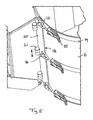
- a slit-shaped clamping jaw 18 is provided on the axial connection sides of the connection body 7, into which the sieve elements 10 can each be pushed.
- FIGS. 4 and 5 show these Klemmmäuler 18 right and left of the inlet shaft 8 each of a - roughly speaking - tangentially extending edge web 19 and a terminal strip over this edge web 20 20 formed about a hinge axis 21 parallel to the longitudinal axis of the screen 6 pivotally mounted on the connector body 7 is fastened.
- the terminal strip 20 can be separated by axial pulling of the connector body 7, in which case the hinge pin 21 solve that form the articulated connection of the terminal block 20 with the connector body 7.
- the tension straps 14 are articulated to the said terminal block 20, the corresponding thereto Einitatir 18, to which the hooking means 17 of the clamping lever 15 can be mounted. If the tensioning levers 15 and thereby the tension straps 14 are tensioned, the edges of the strainer elements 10 under the clamping strip 20 are clamped, since the clamping strip 20 rotates about the hinge pins 21 and performs a corresponding clamping movement.
Landscapes
- Engineering & Computer Science (AREA)
- Mechanical Engineering (AREA)
- General Engineering & Computer Science (AREA)
- Health & Medical Sciences (AREA)
- Life Sciences & Earth Sciences (AREA)
- Molecular Biology (AREA)
- Centrifugal Separators (AREA)
- Filtering Of Dispersed Particles In Gases (AREA)
- Drying Of Solid Materials (AREA)
Claims (14)
- Sécheur centrifuge (1) pour la séparation de matières granulaires d'un fluide, avec un boîtier (2), un rotor (4) disposé dans le boîtier (2) ainsi qu'un tamis (6) entourant le rotor (4) côté pourtour, où le tamis (6) présente au moins un élément de tamisage poreux (10) qui forme au moins un secteur des faces d'enveloppe et est posé en forme d'arc autour d'au moins un cerceau de support de tamis (11) et est fixé amoviblement à celui-ci, et où le tamis (6) peut être relié à un corps de raccordement (7) disposé sur le pourtour, dans la zone duquel le tamis (6) présente un évidement périphérique, dans lequel aucun élément de tamisage (10) n'est disposé, caractérisé en ce que le tamis (6), vu dans le sens du pourtour, présente des extrémités d'éléments de tamisage se chevauchant entre elles qui sont serrées par respectivement au moins une sangle de serrage (14) qui entoure les éléments de tamisage (10) se chevauchant entre elles au côté périphérique, sur le cerceau de support de tamis (11), en ce que le corps de raccordement (7) est fixé par au moins une sangle de serrage (14) au tamis (6), qui entoure et fixe en même temps un élément de tamisage (10) prévu dans la zone du corps de raccordement (7), et en ce que le corps de raccordement (7), dans la zone de côtés avoisinant le tamis (6), présente des gueules ou baguettes de serrage (18; 20) par lesquelles un élément de tamisage (10) avoisinant à chaque fois le corps de raccordement (7), peut être serré avec une extrémité d'élément de tamisage chevauchant le corps de raccordement (7) dans la direction périphérique.
- Sécheur centrifuge (1) selon la revendication précédente, où les éléments de tamisage (10) eux-mêmes sont exempts d'éléments de fixation et de retenue, dans leurs sections se chevauchant mutuellement, reposent lâchement les uns sur les autres et sont retenus exclusivement par au moins une sangle de serrage précitée (14).
- Séchoir centrifuge (1) selon l'une des revendications précédentes, où les éléments de tamisage (10) sont réalisés sans point de soudure et sans cordon de soudure.
- Séchoir centrifuge (1) selon l'une des revendications précédentes, où le tamis (6) est disposé en rotation autour d'un axe debout, et le rotor (4) est disposé par rapport au tamis (6) d'une manière tournante.
- Séchoir centrifuge (1) selon l'une des revendications précédentes, où le tamis (6) présente au moins deux cerceaux de support de tamis (11) qui sont disposés de préférence à des sections d'extrémité aux deux côtés des éléments de tamisage, où les éléments de tamisage (10) sont tendus par des sangles de serrage correspondantes (14) sur chacun des cerceaux de support de tamis.
- Séchoir centrifuge (1) selon l'une des revendications précédentes, où le tamis (6), vu en direction axiale, est constitué de plusieurs éléments de tamisage (10) qui sont fixés respectivement individuellement par des sangles de serrage (14) sur des cerceaux de support de tamis, où est prévu entre deux sections de tamisage (6a, 6b) avoisinantes dans la direction axiale un cerceau de support de tamis commun (11) sur lequel, vu en direction axiale, plusieurs éléments de tamisage des deux sections de tamisage (6a, 6b) sont tendus, où le cerceau de support de tamis commun (11) présente dans une section médiane une baguette de séparation radiale qui sépare deux sections de tension axialement séparées sur le côté du pourtour et vers laquelle les sections de tamisage (6a, 6b) peuvent être orientées depuis des côtés opposés à la manière d'une butée lors de la tension, où les deux sections de tamisage (6a, 6b) sont fixées chacune par une sangle de serrage (14) sur une des sections de tension côté pourtour du cerceau de support de tamis commun (11).
- Sécheur centrifuge (1) selon l'une des revendications précédentes, dans lequel le tamis (6) est constitué dans sa section de tamis (6a), à laquelle peut être relié le corps de raccordement (7), vu en direction périphérique, de plusieurs éléments de tamisage (10) qui sont déplaçables dans la direction périphérique dans leur zone de recouvrement (12) les uns relativement aux autres.
- Sécheur centrifuge (1) selon l'une des revendications précédentes, dans lequel les gueules de serrage (18) peuvent être serrées par au moins une sangle de serrage (14).
- Sécheur centrifuge (1) selon la revendication précédente, où les baguettes de serrage (20) peuvent être accrochées au moyen de boulons d'articulation à charnière (21) amoviblement et d'une manière articulée au corps de raccordement (7), en particulier peuvent être enclenchées dans la direction axiale.
- Sécheur centrifuge (1) selon l'une des revendications précédentes, où sont prévus au corps de raccordement (7) des points d'articulation pour au moins une sangle de serrage précitée (14).
- Sécheur centrifuge (1) selon l'une des revendications précédentes, dans lequel au moins un cerceau de support de tamis (11) peut être appliqué et/ou fixé au corps de raccordement (7).
- Sécheur centrifuge (1) selon l'une des revendications précédentes, dans lequel la sangle de serrage (14) présente un moyen de serrage actionnable sans outil, de préférence est munie à une extrémité d'un levier de serrage (15) et à son autre extrémité d'un accrochage (16) pour le levier de serrage (15) et/ou un autre levier de serrage (15).
- Sécheur centrifuge (1) selon l'une des revendications précédentes, dans lequel la au moins une sangle de serrage (14) est assurée à au moins un des éléments de tamisage (10) à l'encontre d'un glissement, de préférence est reliée par au moins un point de soudure, un collage ou analogue à l'élément de tamisage (10).
- Sécheur centrifuge (1) selon l'une des revendications 1 à 12, dans lequel les éléments de tamisage (10), dans la direction périphérique, lorsque la sangle de serrage (14) est relâchée, sont déplaçables les uns relativement aux autres.
Priority Applications (1)
| Application Number | Priority Date | Filing Date | Title |
|---|---|---|---|
| PL08716616T PL2135023T3 (pl) | 2007-03-19 | 2008-03-18 | Suszarka odśrodkowa |
Applications Claiming Priority (3)
| Application Number | Priority Date | Filing Date | Title |
|---|---|---|---|
| DE202007003978 | 2007-03-19 | ||
| DE202007004462U DE202007004462U1 (de) | 2007-03-19 | 2007-03-27 | Zentrifugaltrockner |
| PCT/EP2008/002168 WO2008113560A2 (fr) | 2007-03-19 | 2008-03-18 | Sécheur centrifuge |
Publications (2)
| Publication Number | Publication Date |
|---|---|
| EP2135023A2 EP2135023A2 (fr) | 2009-12-23 |
| EP2135023B1 true EP2135023B1 (fr) | 2011-09-28 |
Family
ID=39670441
Family Applications (1)
| Application Number | Title | Priority Date | Filing Date |
|---|---|---|---|
| EP08716616A Active EP2135023B1 (fr) | 2007-03-19 | 2008-03-18 | Sécheur centrifuge |
Country Status (10)
| Country | Link |
|---|---|
| US (1) | US8365430B2 (fr) |
| EP (1) | EP2135023B1 (fr) |
| KR (1) | KR101534875B1 (fr) |
| CN (1) | CN101675312B (fr) |
| AT (1) | ATE526546T1 (fr) |
| BR (1) | BRPI0809268B1 (fr) |
| DE (1) | DE202007004462U1 (fr) |
| PL (1) | PL2135023T3 (fr) |
| TW (1) | TWI468227B (fr) |
| WO (1) | WO2008113560A2 (fr) |
Families Citing this family (24)
| Publication number | Priority date | Publication date | Assignee | Title |
|---|---|---|---|---|
| EP1902825B1 (fr) * | 2006-09-20 | 2011-11-09 | ECON Maschinenbau und Steuerungstechnik GmbH | Dispositif pour la déshydratation et le séchage de matières solides, notamment des matières synthétiques obtenues par granulation sous l'eau |
| US8220177B2 (en) * | 2007-05-23 | 2012-07-17 | Gala Industries, Inc. | Centrifugal pellet dryer screen with integral embossed deflector strips |
| US8205350B2 (en) | 2008-09-02 | 2012-06-26 | Gala Industries, Inc. | Dryer system with improved throughput |
| SG173604A1 (en) | 2009-02-24 | 2011-09-29 | Gala Inc | Continuous bagging processes and systems |
| US9925694B2 (en) | 2009-02-24 | 2018-03-27 | Gala Industries, Inc. | Continuous bagging processes and systems |
| BRPI1008610A2 (pt) | 2009-06-22 | 2016-03-15 | Gala Inc | sistemas de peletização, secagem e ensacamento contínuos com produtividade aperfeiçoada |
| RU2410616C1 (ru) * | 2009-09-16 | 2011-01-27 | Открытое акционерное общество "Корпорация "Росхимзащита" (ОАО "Корпорация "Росхимзащита") | Центробежная сушилка |
| RU2426047C1 (ru) * | 2010-03-16 | 2011-08-10 | Федеральное государственное образовательное учреждение высшего профессионального образования "Алтайский государственный аграрный университет" (АГАУ) | Карусельная сушилка |
| RU2425308C1 (ru) * | 2010-03-24 | 2011-07-27 | Федеральное государственное образовательное учреждение высшего профессионального образования "Алтайский государственный аграрный университет" (АГАУ) | Карусельная сушилка (варианты) |
| US20150000152A1 (en) * | 2013-06-26 | 2015-01-01 | Gala Industries, Inc. | Centrifugal pellet dryer screen with integral outwardly projecting deflector strips |
| BR112017005137A2 (pt) * | 2014-09-16 | 2018-01-23 | Gala Inc | sistemas e métodos para secagem de pellets e outros materiais |
| DE102014013438A1 (de) * | 2014-09-16 | 2016-03-17 | Siebtechnik Gmbh | Einlaufkrümmer mit Bogensieb |
| US10557665B2 (en) * | 2016-10-14 | 2020-02-11 | Gala Industries, Inc. | Centrifugal pellet dryer |
| US10648734B2 (en) * | 2016-10-14 | 2020-05-12 | Gala Industries, Inc. | Centrifugal pellet dryer |
| US10041732B2 (en) | 2016-10-14 | 2018-08-07 | Gala Industries, Inc. | Pellet dryer with outlet guidance plate |
| US10655915B2 (en) | 2016-10-14 | 2020-05-19 | Gala Industries, Inc. | Pellet dryer with additional blower |
| EP3546871B1 (fr) * | 2018-03-28 | 2020-12-02 | Nordson Corporation | Dispositif de séparation permettant de séparer une matière solide à partir d'un dflux de refoulement et procédé de maintenance d'un tel dispositif de séparation |
| CN109297293A (zh) * | 2018-04-17 | 2019-02-01 | 张家港市丁氏机械有限公司 | 一种固液分离干燥一体机 |
| CN110064528B (zh) * | 2019-05-07 | 2020-03-17 | 中国矿业大学 | 一种用于干燥分选矿物的干法提质系统及提质方法 |
| CN110548328A (zh) * | 2019-08-26 | 2019-12-10 | 浙江圣兆药物科技股份有限公司 | 一种微球筛网、生产型高效微球收集装置及其应用 |
| CN111678329B (zh) * | 2020-06-20 | 2021-09-21 | 广西正丰建设集团有限公司 | 一种建筑沙石自动干燥分离方法 |
| US12429077B2 (en) | 2021-04-28 | 2025-09-30 | Maag Gala, Inc. | Dryer screen quick release latch |
| CN118517861B (zh) * | 2024-07-18 | 2024-09-20 | 云南省农业科学院药用植物研究所 | 一种用于滇黄精的切片干燥装置及使用方法 |
| CN120576557B (zh) * | 2025-08-01 | 2025-10-31 | 介休瑞昇昌洗煤设备制造有限公司 | 一种洗煤机用脱水装置 |
Family Cites Families (14)
| Publication number | Priority date | Publication date | Assignee | Title |
|---|---|---|---|---|
| US301803A (en) * | 1884-07-08 | Bolting-reel for flou r-ivii lls | ||
| US1428010A (en) * | 1921-07-14 | 1922-09-05 | Daniels Edmund | Lock joint for centrifugal screens and method of forming the same |
| DE1432766A1 (de) * | 1961-03-09 | 1969-01-16 | Ajem Lab Inc | Drehfilter und Filtrierverfahren |
| US3241675A (en) * | 1962-06-04 | 1966-03-22 | Ajem Lab Inc | Rotary filter and method |
| US3458045A (en) * | 1966-08-26 | 1969-07-29 | Gala Inc | Centrifugal pellet drier |
| US4190678A (en) * | 1976-05-04 | 1980-02-26 | Aunt Nellie's Foods, Inc. | Method and apparatus for dewatering vegetables and the like |
| DE3801383A1 (de) | 1988-01-19 | 1989-07-27 | Linnhoff Maschinenbau | Siebtrommel |
| US5265347A (en) * | 1992-09-04 | 1993-11-30 | Gala Industries, Inc. | Centrifugal pellet dryer |
| US6138375A (en) * | 1999-03-01 | 2000-10-31 | Gala Industries, Inc. | Support ring for pellet dryer screen |
| US6438866B1 (en) | 2000-02-10 | 2002-08-27 | Carter Day International, Inc. | Flow disrupter for dryers |
| US6467188B1 (en) | 2000-10-10 | 2002-10-22 | The Conair Group, Inc. | Centrifugal pellet dryer apparatus |
| US6739457B2 (en) | 2001-08-17 | 2004-05-25 | Gala Industries, Inc. | Deflector for centrifugal pellet dryer screen |
| CN1236855C (zh) * | 2002-03-05 | 2006-01-18 | 高根树 | 内旋转子过滤离心机 |
| US7024794B1 (en) * | 2004-10-15 | 2006-04-11 | Gala Industries | Centrifugal pellet dryer with plastic wall panels |
-
2007
- 2007-03-27 DE DE202007004462U patent/DE202007004462U1/de not_active Expired - Lifetime
-
2008
- 2008-03-18 KR KR1020097021397A patent/KR101534875B1/ko active Active
- 2008-03-18 BR BRPI0809268-0A patent/BRPI0809268B1/pt not_active IP Right Cessation
- 2008-03-18 PL PL08716616T patent/PL2135023T3/pl unknown
- 2008-03-18 AT AT08716616T patent/ATE526546T1/de active
- 2008-03-18 TW TW97109440A patent/TWI468227B/zh active
- 2008-03-18 EP EP08716616A patent/EP2135023B1/fr active Active
- 2008-03-18 US US12/450,306 patent/US8365430B2/en active Active
- 2008-03-18 CN CN2008800092186A patent/CN101675312B/zh active Active
- 2008-03-18 WO PCT/EP2008/002168 patent/WO2008113560A2/fr not_active Ceased
Also Published As
| Publication number | Publication date |
|---|---|
| TWI468227B (zh) | 2015-01-11 |
| CN101675312B (zh) | 2012-07-04 |
| BRPI0809268A2 (pt) | 2014-10-14 |
| KR20090130049A (ko) | 2009-12-17 |
| ATE526546T1 (de) | 2011-10-15 |
| US20100037477A1 (en) | 2010-02-18 |
| WO2008113560A3 (fr) | 2009-01-08 |
| CN101675312A (zh) | 2010-03-17 |
| TW200902155A (en) | 2009-01-16 |
| BRPI0809268B1 (pt) | 2019-07-02 |
| US8365430B2 (en) | 2013-02-05 |
| WO2008113560A2 (fr) | 2008-09-25 |
| DE202007004462U1 (de) | 2008-07-31 |
| EP2135023A2 (fr) | 2009-12-23 |
| PL2135023T3 (pl) | 2012-02-29 |
| KR101534875B1 (ko) | 2015-07-07 |
Similar Documents
| Publication | Publication Date | Title |
|---|---|---|
| EP2135023B1 (fr) | Sécheur centrifuge | |
| DE2405854C3 (de) | Filterpresse | |
| DE3227160A1 (de) | Rollballen aus landwirtschaftlichem halmgut | |
| DE19819980B4 (de) | Filtereinrichtung für eine Prozeßapparatur | |
| WO2014170450A1 (fr) | Palette, rail de palettes, arbre d'un mélangeur, mélangeur et un procédé pour mélanger | |
| DE202016006452U1 (de) | Granulat-Zentrifugaltrockner | |
| DE3614738C2 (fr) | ||
| EP1777161B1 (fr) | Machine pour emballer un produit fluide ou granuleux | |
| DE2244174A1 (de) | Foerdervorrichtung fuer zigaretten od.dgl | |
| DE1461111A1 (de) | Trockner fuer Nasspapierbahnen in Papiermaschinen | |
| DE2941802C2 (de) | Vorrichtung zum Auspressen von fließfähigen Massen | |
| EP0891808B1 (fr) | Tambour pour recevoir un produit en particule, dispositif contenant un tambour et procédé pour la fabrication du tambour | |
| DE4018655A1 (de) | Luftfilter | |
| AT412259B (de) | Verfahren zum herstellen eines sektorförmigen filterelements und filterelement | |
| DE4407515C1 (de) | Vorrichtung zum Einspannen eines Filtermittels in einer Zentrifugentrommel | |
| DE3402637C2 (fr) | ||
| DE1814330B2 (de) | Verfahren und Vorrichtung zum Reinigen einer Siebtrommel | |
| EP0935111B1 (fr) | Procédé et dispositif de séchage de capsules biopolymères molles, notamment capsules de gélatine molle | |
| DE9311939U1 (de) | Abbindevorrichtung für eine Wurstabfüllmaschine | |
| DE3816214A1 (de) | Drehsieb | |
| DE2146894C3 (de) | Vorrichtung mit einer allseitig geschlossenen Stauchkammer | |
| DE102023103834A1 (de) | Landwirtschaftliche Erntemaschine mit Erntegutwalze | |
| DE2119645A1 (de) | Trocknungstrommel | |
| AT18121U1 (de) | Drehbare Lagerung eines tragenden Elementes eines Filters | |
| DE8010997U1 (de) | Kontinuierlich arbeitende siebzentrifuge |
Legal Events
| Date | Code | Title | Description |
|---|---|---|---|
| PUAI | Public reference made under article 153(3) epc to a published international application that has entered the european phase |
Free format text: ORIGINAL CODE: 0009012 |
|
| 17P | Request for examination filed |
Effective date: 20090922 |
|
| AK | Designated contracting states |
Kind code of ref document: A2 Designated state(s): AT BE BG CH CY CZ DE DK EE ES FI FR GB GR HR HU IE IS IT LI LT LU LV MC MT NL NO PL PT RO SE SI SK TR |
|
| 17Q | First examination report despatched |
Effective date: 20100303 |
|
| GRAP | Despatch of communication of intention to grant a patent |
Free format text: ORIGINAL CODE: EPIDOSNIGR1 |
|
| GRAS | Grant fee paid |
Free format text: ORIGINAL CODE: EPIDOSNIGR3 |
|
| GRAA | (expected) grant |
Free format text: ORIGINAL CODE: 0009210 |
|
| AK | Designated contracting states |
Kind code of ref document: B1 Designated state(s): AT BE BG CH CY CZ DE DK EE ES FI FR GB GR HR HU IE IS IT LI LT LU LV MC MT NL NO PL PT RO SE SI SK TR |
|
| REG | Reference to a national code |
Ref country code: GB Ref legal event code: FG4D Free format text: NOT ENGLISH |
|
| REG | Reference to a national code |
Ref country code: CH Ref legal event code: EP |
|
| REG | Reference to a national code |
Ref country code: IE Ref legal event code: FG4D |
|
| REG | Reference to a national code |
Ref country code: SE Ref legal event code: TRGR |
|
| REG | Reference to a national code |
Ref country code: DE Ref legal event code: R096 Ref document number: 502008005030 Country of ref document: DE Effective date: 20111222 |
|
| REG | Reference to a national code |
Ref country code: NL Ref legal event code: T3 |
|
| PG25 | Lapsed in a contracting state [announced via postgrant information from national office to epo] |
Ref country code: NO Free format text: LAPSE BECAUSE OF FAILURE TO SUBMIT A TRANSLATION OF THE DESCRIPTION OR TO PAY THE FEE WITHIN THE PRESCRIBED TIME-LIMIT Effective date: 20111228 Ref country code: HR Free format text: LAPSE BECAUSE OF FAILURE TO SUBMIT A TRANSLATION OF THE DESCRIPTION OR TO PAY THE FEE WITHIN THE PRESCRIBED TIME-LIMIT Effective date: 20110928 Ref country code: FI Free format text: LAPSE BECAUSE OF FAILURE TO SUBMIT A TRANSLATION OF THE DESCRIPTION OR TO PAY THE FEE WITHIN THE PRESCRIBED TIME-LIMIT Effective date: 20110928 Ref country code: LT Free format text: LAPSE BECAUSE OF FAILURE TO SUBMIT A TRANSLATION OF THE DESCRIPTION OR TO PAY THE FEE WITHIN THE PRESCRIBED TIME-LIMIT Effective date: 20110928 |
|
| LTIE | Lt: invalidation of european patent or patent extension |
Effective date: 20110928 |
|
| PG25 | Lapsed in a contracting state [announced via postgrant information from national office to epo] |
Ref country code: CY Free format text: LAPSE BECAUSE OF FAILURE TO SUBMIT A TRANSLATION OF THE DESCRIPTION OR TO PAY THE FEE WITHIN THE PRESCRIBED TIME-LIMIT Effective date: 20110928 Ref country code: SI Free format text: LAPSE BECAUSE OF FAILURE TO SUBMIT A TRANSLATION OF THE DESCRIPTION OR TO PAY THE FEE WITHIN THE PRESCRIBED TIME-LIMIT Effective date: 20110928 Ref country code: GR Free format text: LAPSE BECAUSE OF FAILURE TO SUBMIT A TRANSLATION OF THE DESCRIPTION OR TO PAY THE FEE WITHIN THE PRESCRIBED TIME-LIMIT Effective date: 20111229 Ref country code: LV Free format text: LAPSE BECAUSE OF FAILURE TO SUBMIT A TRANSLATION OF THE DESCRIPTION OR TO PAY THE FEE WITHIN THE PRESCRIBED TIME-LIMIT Effective date: 20110928 |
|
| REG | Reference to a national code |
Ref country code: PL Ref legal event code: T3 |
|
| REG | Reference to a national code |
Ref country code: IE Ref legal event code: FD4D |
|
| PG25 | Lapsed in a contracting state [announced via postgrant information from national office to epo] |
Ref country code: IS Free format text: LAPSE BECAUSE OF FAILURE TO SUBMIT A TRANSLATION OF THE DESCRIPTION OR TO PAY THE FEE WITHIN THE PRESCRIBED TIME-LIMIT Effective date: 20120128 Ref country code: SK Free format text: LAPSE BECAUSE OF FAILURE TO SUBMIT A TRANSLATION OF THE DESCRIPTION OR TO PAY THE FEE WITHIN THE PRESCRIBED TIME-LIMIT Effective date: 20110928 |
|
| PG25 | Lapsed in a contracting state [announced via postgrant information from national office to epo] |
Ref country code: EE Free format text: LAPSE BECAUSE OF FAILURE TO SUBMIT A TRANSLATION OF THE DESCRIPTION OR TO PAY THE FEE WITHIN THE PRESCRIBED TIME-LIMIT Effective date: 20110928 Ref country code: PT Free format text: LAPSE BECAUSE OF FAILURE TO SUBMIT A TRANSLATION OF THE DESCRIPTION OR TO PAY THE FEE WITHIN THE PRESCRIBED TIME-LIMIT Effective date: 20120130 Ref country code: RO Free format text: LAPSE BECAUSE OF FAILURE TO SUBMIT A TRANSLATION OF THE DESCRIPTION OR TO PAY THE FEE WITHIN THE PRESCRIBED TIME-LIMIT Effective date: 20110928 |
|
| PG25 | Lapsed in a contracting state [announced via postgrant information from national office to epo] |
Ref country code: DK Free format text: LAPSE BECAUSE OF FAILURE TO SUBMIT A TRANSLATION OF THE DESCRIPTION OR TO PAY THE FEE WITHIN THE PRESCRIBED TIME-LIMIT Effective date: 20110928 Ref country code: IE Free format text: LAPSE BECAUSE OF FAILURE TO SUBMIT A TRANSLATION OF THE DESCRIPTION OR TO PAY THE FEE WITHIN THE PRESCRIBED TIME-LIMIT Effective date: 20110928 |
|
| PLBE | No opposition filed within time limit |
Free format text: ORIGINAL CODE: 0009261 |
|
| STAA | Information on the status of an ep patent application or granted ep patent |
Free format text: STATUS: NO OPPOSITION FILED WITHIN TIME LIMIT |
|
| 26N | No opposition filed |
Effective date: 20120629 |
|
| REG | Reference to a national code |
Ref country code: DE Ref legal event code: R097 Ref document number: 502008005030 Country of ref document: DE Effective date: 20120629 |
|
| PG25 | Lapsed in a contracting state [announced via postgrant information from national office to epo] |
Ref country code: MC Free format text: LAPSE BECAUSE OF NON-PAYMENT OF DUE FEES Effective date: 20120331 |
|
| REG | Reference to a national code |
Ref country code: CH Ref legal event code: PL |
|
| PG25 | Lapsed in a contracting state [announced via postgrant information from national office to epo] |
Ref country code: CH Free format text: LAPSE BECAUSE OF NON-PAYMENT OF DUE FEES Effective date: 20120331 Ref country code: LI Free format text: LAPSE BECAUSE OF NON-PAYMENT OF DUE FEES Effective date: 20120331 |
|
| PG25 | Lapsed in a contracting state [announced via postgrant information from national office to epo] |
Ref country code: ES Free format text: LAPSE BECAUSE OF FAILURE TO SUBMIT A TRANSLATION OF THE DESCRIPTION OR TO PAY THE FEE WITHIN THE PRESCRIBED TIME-LIMIT Effective date: 20120108 |
|
| PG25 | Lapsed in a contracting state [announced via postgrant information from national office to epo] |
Ref country code: BG Free format text: LAPSE BECAUSE OF FAILURE TO SUBMIT A TRANSLATION OF THE DESCRIPTION OR TO PAY THE FEE WITHIN THE PRESCRIBED TIME-LIMIT Effective date: 20111228 |
|
| PG25 | Lapsed in a contracting state [announced via postgrant information from national office to epo] |
Ref country code: MT Free format text: LAPSE BECAUSE OF FAILURE TO SUBMIT A TRANSLATION OF THE DESCRIPTION OR TO PAY THE FEE WITHIN THE PRESCRIBED TIME-LIMIT Effective date: 20110928 |
|
| PGFP | Annual fee paid to national office [announced via postgrant information from national office to epo] |
Ref country code: SE Payment date: 20140324 Year of fee payment: 7 |
|
| PG25 | Lapsed in a contracting state [announced via postgrant information from national office to epo] |
Ref country code: LU Free format text: LAPSE BECAUSE OF NON-PAYMENT OF DUE FEES Effective date: 20120318 |
|
| PGFP | Annual fee paid to national office [announced via postgrant information from national office to epo] |
Ref country code: TR Payment date: 20140314 Year of fee payment: 7 |
|
| PG25 | Lapsed in a contracting state [announced via postgrant information from national office to epo] |
Ref country code: HU Free format text: LAPSE BECAUSE OF FAILURE TO SUBMIT A TRANSLATION OF THE DESCRIPTION OR TO PAY THE FEE WITHIN THE PRESCRIBED TIME-LIMIT Effective date: 20080318 |
|
| REG | Reference to a national code |
Ref country code: FR Ref legal event code: PLFP Year of fee payment: 8 |
|
| PGFP | Annual fee paid to national office [announced via postgrant information from national office to epo] |
Ref country code: FR Payment date: 20150319 Year of fee payment: 8 Ref country code: GB Payment date: 20150319 Year of fee payment: 8 Ref country code: PL Payment date: 20150225 Year of fee payment: 8 |
|
| PG25 | Lapsed in a contracting state [announced via postgrant information from national office to epo] |
Ref country code: SE Free format text: LAPSE BECAUSE OF NON-PAYMENT OF DUE FEES Effective date: 20150319 |
|
| REG | Reference to a national code |
Ref country code: SE Ref legal event code: EUG |
|
| PGFP | Annual fee paid to national office [announced via postgrant information from national office to epo] |
Ref country code: NL Payment date: 20160317 Year of fee payment: 9 Ref country code: CZ Payment date: 20160303 Year of fee payment: 9 |
|
| GBPC | Gb: european patent ceased through non-payment of renewal fee |
Effective date: 20160318 |
|
| REG | Reference to a national code |
Ref country code: FR Ref legal event code: ST Effective date: 20161130 |
|
| PG25 | Lapsed in a contracting state [announced via postgrant information from national office to epo] |
Ref country code: FR Free format text: LAPSE BECAUSE OF NON-PAYMENT OF DUE FEES Effective date: 20160331 Ref country code: GB Free format text: LAPSE BECAUSE OF NON-PAYMENT OF DUE FEES Effective date: 20160318 |
|
| PG25 | Lapsed in a contracting state [announced via postgrant information from national office to epo] |
Ref country code: TR Free format text: LAPSE BECAUSE OF NON-PAYMENT OF DUE FEES Effective date: 20150318 Ref country code: PL Free format text: LAPSE BECAUSE OF NON-PAYMENT OF DUE FEES Effective date: 20160318 |
|
| PG25 | Lapsed in a contracting state [announced via postgrant information from national office to epo] |
Ref country code: CZ Free format text: LAPSE BECAUSE OF NON-PAYMENT OF DUE FEES Effective date: 20170318 |
|
| REG | Reference to a national code |
Ref country code: NL Ref legal event code: MM Effective date: 20170401 |
|
| PG25 | Lapsed in a contracting state [announced via postgrant information from national office to epo] |
Ref country code: NL Free format text: LAPSE BECAUSE OF NON-PAYMENT OF DUE FEES Effective date: 20170401 |
|
| PGFP | Annual fee paid to national office [announced via postgrant information from national office to epo] |
Ref country code: DE Payment date: 20260319 Year of fee payment: 19 |
|
| PGFP | Annual fee paid to national office [announced via postgrant information from national office to epo] |
Ref country code: AT Payment date: 20260320 Year of fee payment: 19 |
|
| PGFP | Annual fee paid to national office [announced via postgrant information from national office to epo] |
Ref country code: BE Payment date: 20260319 Year of fee payment: 19 Ref country code: IT Payment date: 20260324 Year of fee payment: 19 |