EP2136042A1 - Système d'échappement - Google Patents
Système d'échappement Download PDFInfo
- Publication number
- EP2136042A1 EP2136042A1 EP09251568A EP09251568A EP2136042A1 EP 2136042 A1 EP2136042 A1 EP 2136042A1 EP 09251568 A EP09251568 A EP 09251568A EP 09251568 A EP09251568 A EP 09251568A EP 2136042 A1 EP2136042 A1 EP 2136042A1
- Authority
- EP
- European Patent Office
- Prior art keywords
- exhaust system
- outer cylinder
- tube
- inner cylinder
- diameter
- Prior art date
- Legal status (The legal status is an assumption and is not a legal conclusion. Google has not performed a legal analysis and makes no representation as to the accuracy of the status listed.)
- Granted
Links
Images




Classifications
-
- F—MECHANICAL ENGINEERING; LIGHTING; HEATING; WEAPONS; BLASTING
- F01—MACHINES OR ENGINES IN GENERAL; ENGINE PLANTS IN GENERAL; STEAM ENGINES
- F01N—GAS-FLOW SILENCERS OR EXHAUST APPARATUS FOR MACHINES OR ENGINES IN GENERAL; GAS-FLOW SILENCERS OR EXHAUST APPARATUS FOR INTERNAL-COMBUSTION ENGINES
- F01N1/00—Silencing apparatus characterised by method of silencing
- F01N1/08—Silencing apparatus characterised by method of silencing by reducing exhaust energy by throttling or whirling
- F01N1/085—Silencing apparatus characterised by method of silencing by reducing exhaust energy by throttling or whirling throttling exhaust gas flow using a central core in a flow passage
-
- F—MECHANICAL ENGINEERING; LIGHTING; HEATING; WEAPONS; BLASTING
- F01—MACHINES OR ENGINES IN GENERAL; ENGINE PLANTS IN GENERAL; STEAM ENGINES
- F01N—GAS-FLOW SILENCERS OR EXHAUST APPARATUS FOR MACHINES OR ENGINES IN GENERAL; GAS-FLOW SILENCERS OR EXHAUST APPARATUS FOR INTERNAL-COMBUSTION ENGINES
- F01N1/00—Silencing apparatus characterised by method of silencing
- F01N1/08—Silencing apparatus characterised by method of silencing by reducing exhaust energy by throttling or whirling
- F01N1/10—Silencing apparatus characterised by method of silencing by reducing exhaust energy by throttling or whirling in combination with sound-absorbing materials
-
- F—MECHANICAL ENGINEERING; LIGHTING; HEATING; WEAPONS; BLASTING
- F01—MACHINES OR ENGINES IN GENERAL; ENGINE PLANTS IN GENERAL; STEAM ENGINES
- F01N—GAS-FLOW SILENCERS OR EXHAUST APPARATUS FOR MACHINES OR ENGINES IN GENERAL; GAS-FLOW SILENCERS OR EXHAUST APPARATUS FOR INTERNAL-COMBUSTION ENGINES
- F01N13/00—Exhaust or silencing apparatus characterised by constructional features
- F01N13/18—Construction facilitating manufacture, assembly, or disassembly
- F01N13/1838—Construction facilitating manufacture, assembly, or disassembly characterised by the type of connection between parts of exhaust or silencing apparatus, e.g. between housing and tubes, between tubes and baffles
-
- F—MECHANICAL ENGINEERING; LIGHTING; HEATING; WEAPONS; BLASTING
- F01—MACHINES OR ENGINES IN GENERAL; ENGINE PLANTS IN GENERAL; STEAM ENGINES
- F01N—GAS-FLOW SILENCERS OR EXHAUST APPARATUS FOR MACHINES OR ENGINES IN GENERAL; GAS-FLOW SILENCERS OR EXHAUST APPARATUS FOR INTERNAL-COMBUSTION ENGINES
- F01N2260/00—Exhaust treating devices having provisions not otherwise provided for
- F01N2260/10—Exhaust treating devices having provisions not otherwise provided for for avoiding stress caused by expansions or contractions due to temperature variations
-
- F—MECHANICAL ENGINEERING; LIGHTING; HEATING; WEAPONS; BLASTING
- F01—MACHINES OR ENGINES IN GENERAL; ENGINE PLANTS IN GENERAL; STEAM ENGINES
- F01N—GAS-FLOW SILENCERS OR EXHAUST APPARATUS FOR MACHINES OR ENGINES IN GENERAL; GAS-FLOW SILENCERS OR EXHAUST APPARATUS FOR INTERNAL-COMBUSTION ENGINES
- F01N2470/00—Structure or shape of exhaust gas passages, pipes or tubes
- F01N2470/20—Dimensional characteristics of tubes, e.g. length, diameter
-
- F—MECHANICAL ENGINEERING; LIGHTING; HEATING; WEAPONS; BLASTING
- F01—MACHINES OR ENGINES IN GENERAL; ENGINE PLANTS IN GENERAL; STEAM ENGINES
- F01N—GAS-FLOW SILENCERS OR EXHAUST APPARATUS FOR MACHINES OR ENGINES IN GENERAL; GAS-FLOW SILENCERS OR EXHAUST APPARATUS FOR INTERNAL-COMBUSTION ENGINES
- F01N2470/00—Structure or shape of exhaust gas passages, pipes or tubes
- F01N2470/30—Tubes with restrictions, i.e. venturi or the like, e.g. for sucking air or measuring mass flow
-
- F—MECHANICAL ENGINEERING; LIGHTING; HEATING; WEAPONS; BLASTING
- F01—MACHINES OR ENGINES IN GENERAL; ENGINE PLANTS IN GENERAL; STEAM ENGINES
- F01N—GAS-FLOW SILENCERS OR EXHAUST APPARATUS FOR MACHINES OR ENGINES IN GENERAL; GAS-FLOW SILENCERS OR EXHAUST APPARATUS FOR INTERNAL-COMBUSTION ENGINES
- F01N2590/00—Exhaust or silencing apparatus adapted to particular use, e.g. for military applications, airplanes, submarines
- F01N2590/04—Exhaust or silencing apparatus adapted to particular use, e.g. for military applications, airplanes, submarines for motorcycles
Definitions
- the present invention relates to an exhaust system, for example for a motorcycle, and more particularly, to an exhaust system configured to enhance output while maintaining a necessary noise level.
- JP-A-2006-307793 describes an exhaust system capable of enhancing the silencing effect.
- an outer cylinder and an inner cylinder constituting a muffler are gradually tapered rearward of a vehicle body, and a cross sectional area ratio of the inner and outer cylinders is substantially constant in the front/rear direction.
- the present invention has been accomplished in view of the conventional circumstances, and it is an object of the invention to provide an exhaust system for a motorcycle capable of enhancing output while maintaining a necessary noise level.
- an exhaust system comprising:
- the outlet tube may include a straight tube portion connected to a downstream end of the diverging portion.
- the diameter of the straight tube portion may be substantially equal to the diameter of a downstream end of the diverging portion.
- a rear end of the diverging portion may open toward atmosphere.
- the inner cylinder may include a porous tube having a plurality of holes. An upstream end of said porous tube may be connected to the exhaust pipe and a downstream end may be connected to the converging portion.
- the porous tube and the converging portion may be defined as individual components. These individual components may be separately formed and connected together, or alternatively may be integrally formed.
- the converging portion may have a length substantially equal to the entire length of the outer cylinder.
- the converging portion may define the porous tube.
- the porous tube and the converging portion may be considered to be defined or provided in a single component.
- a sound absorbing material may be located between at least portions of the porous tube and the outer cylinder.
- At least a portion of the outlet tube may project outward from the outer cylinder, and may be surrounded by a cylindrical cover which is connected to the outer cylinder.
- the throttle portion may be bent such that an axis of the diverging portion is directed lower than an axis of the inner cylinder in a state where the exhaust system is in use, for example when attached to a vehicle, such as a motorcycle.
- the exhaust system may further comprise an absorbing arrangement configured to absorb a difference between thermal expansion of the inner cylinder and the outer cylinder.
- the absorbing arrangement may permit relative sliding movement of the inner cylinder and the outer cylinder.
- the throttle portion may include a straight tube portion connected to the converging portion, and a bent tube portion connected to the diverging portion such that the bent tube portion is opposed to the straight tube portion at a distance therebetween.
- the absorbing arrangement may be constituted by slidably supporting the straight tube portion on the outer cylinder.
- the diverging portion may have a length substantially equal to the entire length of the outer cylinder and may define a porous tube having a plurality of holes and a diameter which reduces in a downstream direction.
- the absorbing arrangement may be constituted by relatively slidably joining the throttle portion and the porous tube.
- the exhaust system may be configured for use in a motorcycle.
- a Further aspect of the present invention relates to a vehicle, such as a motorcycle, comprising an exhaust system according to the first aspect.
- Another aspect of the invention relates to a silencer comprising:
- An exhaust system for a motorcycle comprises an exhaust pipe connected to an engine, and a silencer connected to the exhaust pipe, wherein the silencer includes a hermetical cylindrical outer cylinder, and an inner cylinder disposed in the outer cylinder such as to extend along an axis of the outer cylinder, the inner cylinder having a front end portion connected to the exhaust pipe and a rear end portion opening toward atmosphere, and the inner cylinder includes a reduced diameter portion whose diameter becomes smaller toward its downstream, a throttle portion with a constant diameter, which is connected to the reduced diameter portion, and an enlarged diameter portion which is connected to the throttle portion and whose diameter becomes larger toward its downstream.
- the outlet tube of the inner cylinder is constituted by the reduced diameter portion, the throttle portion and the enlarged diameter portion. Due to this, a necessary attenuation effect can be secured by the throttle portion, and air-intake can be increased by controlling a pressure wave in the exhaust pipe at the reduced diameter portion and the enlarged diameter portion. Therefore, the output can be enhanced while maintaining a necessary noise level.
- the diameter of the throttle portion is uniform over the entire outlet tube, the attenuation effect is enhanced but the output is reduced.
- the output can be enhanced but the noise level can not be lowered.
- Figs. 1 to 4 are views for explaining an exhaust system for a motorcycle according to a first embodiment of the invention.
- front, rear, left and right mean front, rear, left and right, respectively as viewed from a person sitting on a seat.
- reference numeral 1 represents a motorcycle.
- the motorcycle 1 includes a body frame 2, an engine 3 mounted to the body frame 2, an exhaust system 4 connected to a front wall of the engine 3, a fuel tank 5 mounted to the body frame 2 above the engine, a seat 6 mounted to a rear side of the fuel tank 5, and an intake apparatus 16 connected to a rear wall of the engine 3.
- a front fork 7 is supported by a head pipe 2a on a front end of the body frame 2 such that the front fork 7 can be steered laterally, a front wheel 8 is pivotally supported on a lower end portion of the front fork 7, and a steering handle 9 is fixed to an upper end portion thereof.
- Reference numeral 10 represents a disk plate of a front wheel brake system, 11 represents a headlight, and 12 represents a speedometer.
- the exhaust system 4 includes an exhaust pipe 14 connected to an exhaust port 3f which opens toward a front wall of a cylinder head 3c of the engine 3, and a silencer 15 connected to a rear end portion of the exhaust pipe 14.
- the exhaust pipe 14 extends downward from the exhaust port 3f while bending forward and downward between left and right down tube portions 2e and 2e, and extends substantially horizontally rearward below the engine, and further extends diagonally rearward and upward.
- the silencer 15 includes a hermetic outer cylinder 16 and an inner cylinder 17 disposed in the outer cylinder 16.
- Reference numeral 21 represents a support bracket provided on the outer cylinder 16, and the silencer 15 is supported by the body frame 2 through the support bracket 21.
- the outer cylinder 16 includes a cylindrical outer cylinder main tube 16a, a front cover 16b connected to a front end portion of the outer cylinder main tube 16a such as to close the front end opening, and a rear cover 16c connected and fixed to a rear end portion of the outer cylinder main tube 16a such as to close the rear end opening.
- a front end portion of the front cover 16b is connected and fixed to a rear end portion of the exhaust pipe 14.
- the inner cylinder 17 includes an inner cylinder main tube 17a disposed coaxially with an axis a of the outer cylinder main tube 16a, an inlet tube 17b connected to a front end portion of the inner cylinder main tube 17a, and an outlet tube 17c connected to a rear end portion.
- the inner cylinder main tube 17a is a porous straight tube formed of a so-called punched pipe having a large number of small-diameter holes 17d. Exhaust gas moves between the inner cylinder main tube 17a and a space b formed between the inner cylinder main tube 17a and the outer cylinder main tube 16a through the small-diameter holes 17d.
- a sound absorbing material, e.g., glass wool 18 is stuffed in the space b.
- the inlet tube 17b has a diameter slightly larger than that of the inner cylinder main tube 17a, and the inlet tube 17b is supported by a front end portion of the outer cylinder main tube 16a through a front support member 19.
- the inlet tube 17b is substantially connected to a rear end opening of the exhaust pipe 14.
- the outlet tube 17c includes a reduced diameter or converging portion 17f which is connected to a rear end of the inner cylinder main tube 17a and which is tapered in a downstream direction, a throttle portion 17g which is connected to the reduced diameter portion 17f and which has a constant diameter, and an enlarged diameter or diverging portion 17h which is connected to the throttle portion 17g and which has a diameter increasing in a downstream direction.
- the throttle portion 17g has a straight tube portion 17i and a bent tube portion 17j.
- an axis a' of the enlarged diameter portion 17h is directed lower than the axis a of the inner cylinder main tube 17a in a state where the exhaust system is mounted on the vehicle. That is, the axis a' of the enlarged diameter portion 17h may be considered to be directed lower relative to the horizon than axis a.
- the axis a' of the enlarged diameter portion 17h can be directed to extend below, towards or above the horizon.
- the straight tube portion 17i is slidably supported by a cylindrical support portion 20a of the rear support member 20. Further, the bent tube portion 17j is fitted and inserted into the support portion 20a, and welded thereto.
- the rear support member 20 is fixed to an inner surface of the outer cylinder main tube 16a. Further, a gap c is provided between the straight tube portion 17i and the bent tube portion 17j. Accordingly, an absorbing mechanism 22 which absorbs a difference in thermal expansion amount between the inner cylinder 17 and the outer cylinder 16 is constituted.
- a rear end opening 17h' of the enlarged diameter portion 17h faces rearward from a rear cover opening 16c' of the rear cover 16c. Peripheral edges of both the openings 17h' and 16c' are fixed.
- a portion of the outlet tube 17c projects rearward from the rear support member 20 which closes the rear end opening of the outer cylinder main tube 16a, and this projecting portion is surrounded by the rear cover 16c which is connected to the outer cylinder main tube 16a.
- the outlet tube 17c includes the reduced diameter portion 17f, the throttle portion 17g and the enlarged diameter portion 17h, it is possible to enhance the output while maintaining the necessary noise level. That is, by setting the diameter of the throttle portion 17g, a necessary attenuation effect can be obtained. Since the reduced diameter portion 17f and the enlarged diameter portion 17h are provided in front of and behind the throttle portion 17g, it is possible to control a pressure wave in the exhaust pipe by setting diameters and lengths of the reduced diameter portion 17f and the enlarged diameter portion 17h, the air-intake can be increased and as a result, the output can be enhanced while maintaining a necessary noise level.
- the enlarged diameter portion 17h is constituted such that its axis a' is directed lower relative to the horizon than axis a, it is possible to prevent exhaust gas from being discharged directly to, for example, a motorcycle behind.
- the exhaust system can be manufactured easily.
- the manufactured reduced diameter portion 17f or a connected portion between the reduced diameter portion 17f and the throttle portion is bent, the exhaust system can not be produced easily.
- the throttle portion 17g is formed by opposing the straight tube portion 17i and the bent tube portion 17j to each other with a gap c therebetween, and the absorbing mechanism or arrangement 22 is constituted by relatively slidably supporting the straight tube portion 17i by the rear support member 20. Therefore, the difference between thermal expansion amounts of the outer cylinder 16 and the inner cylinder 17 caused by the temperature difference therebetween can be absorbed, and the enlarged diameter portion 17h can be directed lower relative to the horizon than axis a.
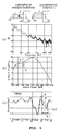
- Figs. 5 show results of experiments for explaining the effect of the apparatus of the present invention.
- Fig. 5(a) shows frequency - attenuation characteristics
- Fig. 5(b) shows engine speed - output shaft torque characteristics
- Fig. 5(c) shows crank angle - pressure characteristics.
- characteristic curves A and B show characteristics of the outlet tube A (example of the present invention) and an outlet tube B (comparative example
- both the outlet tubes A and B have substantially the same attenuation characteristics ( Fig. 5(a) ).
- a shaft torque of the outlet tube A is greater than that of the outlet tube B ( Fig. 5(b) ). This is because that in the case of the outlet tube A, a crank angle ⁇ 1 at which a pressure of the exhaust port in the intake stroke becomes negative pressure is greater than a crank angle ⁇ 2 at which the pressure in the outlet tube B becomes negative pressure and thus, the air-intake increasing effect utilizing a pressure wave and charging efficiency are improved and as a result, the shaft torque is increased.
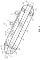
- Fig. 6 is a view for explaining a second embodiment of the present invention.
- the same numerals as those in Fig. 2 represent the same or equivalent elements.
- the reduced diameter portion is constituted such that the inner cylinder main tube 17a' of the inner cylinder 17 tapers in a downstream direction over its entire length.
- the straight tube portion 17i and the bent tube portion 17j are integrally connected to each other without a gap therebetween.
- a gap c is provided between a downstream end of the tapered inner cylinder main tube 17a' and an upstream end of the straight tube portion 17i of the throttle portion 17g'.
- This gap c is covered by slidably inserting the downstream end portion of the inner cylinder main tube 17a' into a slide portion 17k formed on an edge of the upstream end of the straight tube portion 17i. Accordingly, an absorbing mechanism or arrangement 22' which absorbs a difference in thermal expansion amount between the inner cylinder 17 and the outer cylinder 16 is constituted.
- the reduced diameter portion comprises the long inner cylinder main tube 17a'
- the diameter-reducing ratio is gentle, a pressure loss caused by reducing the diameter becomes smaller, exhaust gas flows smoothly, and the reduced diameter portion contributes to enhancement of output.
- Fig. 7 is a view for explaining a third embodiment of the invention, and the same numerals as those in Fig. 2 show the same or equivalent elements.
- a large-diameter straight tube 17m is further connected to a downstream end of the enlarged diameter portion 17h in the third embodiment.
- a diameter of the large-diameter straight tube 17m is set to be the same as that of a downstream end opening of the enlarged diameter portion 17h.
- the exhaust sound can further be reduced without reducing the shaft torque.
Landscapes
- Engineering & Computer Science (AREA)
- Chemical & Material Sciences (AREA)
- Combustion & Propulsion (AREA)
- Mechanical Engineering (AREA)
- General Engineering & Computer Science (AREA)
- Exhaust Silencers (AREA)
Applications Claiming Priority (2)
| Application Number | Priority Date | Filing Date | Title |
|---|---|---|---|
| JP2008158704 | 2008-06-18 | ||
| JP2009060164A JP2010025101A (ja) | 2008-06-18 | 2009-03-12 | 自動二輪車の排気装置 |
Publications (2)
| Publication Number | Publication Date |
|---|---|
| EP2136042A1 true EP2136042A1 (fr) | 2009-12-23 |
| EP2136042B1 EP2136042B1 (fr) | 2013-03-13 |
Family
ID=41055245
Family Applications (1)
| Application Number | Title | Priority Date | Filing Date |
|---|---|---|---|
| EP09251568A Not-in-force EP2136042B1 (fr) | 2008-06-18 | 2009-06-16 | Système d'échappement |
Country Status (3)
| Country | Link |
|---|---|
| US (1) | US8136628B2 (fr) |
| EP (1) | EP2136042B1 (fr) |
| JP (1) | JP2010025101A (fr) |
Cited By (1)
| Publication number | Priority date | Publication date | Assignee | Title |
|---|---|---|---|---|
| EP2216526A1 (fr) * | 2009-01-30 | 2010-08-11 | Honda Motor Co., Ltd. | Couvercle silencieux pour véhicule à monture de selle |
Families Citing this family (7)
| Publication number | Priority date | Publication date | Assignee | Title |
|---|---|---|---|---|
| US20120325578A1 (en) * | 2011-06-21 | 2012-12-27 | E I Du Pont De Nemours And Company | Muffler assembly and method of making |
| JP5850816B2 (ja) * | 2012-09-28 | 2016-02-03 | 本田技研工業株式会社 | 鞍乗型車両の排気装置 |
| JP2014070580A (ja) * | 2012-09-28 | 2014-04-21 | Honda Motor Co Ltd | 鞍乗型車両の排気装置 |
| CN106194368B (zh) * | 2016-07-13 | 2019-03-22 | 安徽奥丰汽车配件有限公司 | 一种低噪音汽车排气管装置 |
| US9856776B1 (en) * | 2016-09-15 | 2018-01-02 | Caterpillar Inc. | Muffler with double shell housing |
| WO2019021194A1 (fr) * | 2017-07-26 | 2019-01-31 | Tvs Motor Company Limited | Dispositif d'échappement pour un véhicule à deux roues |
| US10494977B2 (en) * | 2017-08-07 | 2019-12-03 | Reginald Bernard Carter | Internal straight core |
Citations (5)
| Publication number | Priority date | Publication date | Assignee | Title |
|---|---|---|---|---|
| JPS55125311A (en) | 1979-03-20 | 1980-09-27 | Honda Motor Co Ltd | Exhaust pipe for four-stroke engine |
| JPH0261316A (ja) * | 1988-08-24 | 1990-03-01 | Yamaha Motor Co Ltd | 自動二輪車用排気装置 |
| EP0831211A1 (fr) * | 1995-05-25 | 1998-03-25 | Honda Giken Kogyo Kabushiki Kaisha | Dispositif de regulation de l'emission des gaz d'echappement pour moteurs a combustion interne |
| JP2006307793A (ja) | 2005-04-28 | 2006-11-09 | Honda Motor Co Ltd | 自動2輪車用排気装置 |
| EP1852580A1 (fr) | 2006-05-01 | 2007-11-07 | Yamaha Hatsudoki Kabushiki Kaisha | Dispositif d'échappement et véhicule équipé du dispositif d'échappement |
Family Cites Families (7)
| Publication number | Priority date | Publication date | Assignee | Title |
|---|---|---|---|---|
| US3263772A (en) * | 1964-06-17 | 1966-08-02 | Arvin Ind Inc | Sound attenuating gas conduit with one-quarter wave-length side branch chambers |
| JP2967390B2 (ja) * | 1994-04-21 | 1999-10-25 | 本田技研工業株式会社 | 消音器及びその製造方法 |
| US5633482A (en) * | 1995-10-10 | 1997-05-27 | Two Brothers Racing, Inc. | Motorcycle exhaust system |
| US6571910B2 (en) * | 2000-12-20 | 2003-06-03 | Quiet Storm, Llc | Method and apparatus for improved noise attenuation in a dissipative internal combustion engine exhaust muffler |
| US20020134614A1 (en) * | 2001-03-23 | 2002-09-26 | Shun-Lai Chen | Structure of a muffler at the rear of exhaust pipe |
| US20040089500A1 (en) * | 2002-10-31 | 2004-05-13 | White Brothers Performance Products, Inc. | Muffler with spark arrestor |
| JP4684916B2 (ja) | 2006-02-28 | 2011-05-18 | 本田技研工業株式会社 | 車両の排気装置 |
-
2009
- 2009-03-12 JP JP2009060164A patent/JP2010025101A/ja not_active Withdrawn
- 2009-04-24 US US12/429,961 patent/US8136628B2/en not_active Expired - Fee Related
- 2009-06-16 EP EP09251568A patent/EP2136042B1/fr not_active Not-in-force
Patent Citations (5)
| Publication number | Priority date | Publication date | Assignee | Title |
|---|---|---|---|---|
| JPS55125311A (en) | 1979-03-20 | 1980-09-27 | Honda Motor Co Ltd | Exhaust pipe for four-stroke engine |
| JPH0261316A (ja) * | 1988-08-24 | 1990-03-01 | Yamaha Motor Co Ltd | 自動二輪車用排気装置 |
| EP0831211A1 (fr) * | 1995-05-25 | 1998-03-25 | Honda Giken Kogyo Kabushiki Kaisha | Dispositif de regulation de l'emission des gaz d'echappement pour moteurs a combustion interne |
| JP2006307793A (ja) | 2005-04-28 | 2006-11-09 | Honda Motor Co Ltd | 自動2輪車用排気装置 |
| EP1852580A1 (fr) | 2006-05-01 | 2007-11-07 | Yamaha Hatsudoki Kabushiki Kaisha | Dispositif d'échappement et véhicule équipé du dispositif d'échappement |
Cited By (2)
| Publication number | Priority date | Publication date | Assignee | Title |
|---|---|---|---|---|
| EP2216526A1 (fr) * | 2009-01-30 | 2010-08-11 | Honda Motor Co., Ltd. | Couvercle silencieux pour véhicule à monture de selle |
| US8220587B2 (en) | 2009-01-30 | 2012-07-17 | Honda Motor Co., Ltd. | Silencer cover for saddle-ride type vehicle |
Also Published As
| Publication number | Publication date |
|---|---|
| US8136628B2 (en) | 2012-03-20 |
| JP2010025101A (ja) | 2010-02-04 |
| US20090313982A1 (en) | 2009-12-24 |
| EP2136042B1 (fr) | 2013-03-13 |
Similar Documents
| Publication | Publication Date | Title |
|---|---|---|
| EP2136042B1 (fr) | Système d'échappement | |
| EP3431724B1 (fr) | Dispositif d'échappement pour moteur à combustion interne | |
| EP1840343B1 (fr) | Pot d'échappement pour véhicules de type à enfourcher et véhicule de type à enfourcher | |
| EP1710428B1 (fr) | Structure de tubulure d'air d'admission | |
| US20110073209A1 (en) | Flexible vibration absorbing tube | |
| CN101029586B (zh) | 车辆排气装置 | |
| JP2006017124A (ja) | 自動二輪車用ダイナミック排気システム | |
| US7549510B2 (en) | Vehicle exhaust system | |
| CN101240730A (zh) | 机动二轮车的催化剂配置构造 | |
| JP5161898B2 (ja) | 排気ガス流の加速装置 | |
| EP2159391B1 (fr) | Dispositif de purification de gaz d'échappement pour moteur | |
| JP6318101B2 (ja) | 車両用排気装置 | |
| CN101268262B (zh) | 消声器组件以及用于组装消声器的方法 | |
| US20070158135A1 (en) | Muffler and Vehicle Equipped with Muffler | |
| JP7384112B2 (ja) | マフラ | |
| CN100400812C (zh) | 具有排气净化功能的发动机 | |
| CN211819605U (zh) | 非接触式消声器排烟结构 | |
| JP7344947B2 (ja) | 鞍乗り型車両におけるエアクリーナ構造 | |
| CN222350802U (zh) | 摩托车消声器总成及摩托车 | |
| JP5853356B2 (ja) | エンジンの排気装置 | |
| WO2020089930A1 (fr) | Moteur à combustion interne et son procédé de fabrication | |
| CN115380154A (zh) | 内燃发动机及其套筒构件 | |
| EP1703098B1 (fr) | Dispositif de purification des gaz d'échappement | |
| JPH09137723A (ja) | 内燃機関の排気装置 | |
| JP5659887B2 (ja) | 内燃機関の消音器 |
Legal Events
| Date | Code | Title | Description |
|---|---|---|---|
| PUAI | Public reference made under article 153(3) epc to a published international application that has entered the european phase |
Free format text: ORIGINAL CODE: 0009012 |
|
| 17P | Request for examination filed |
Effective date: 20090624 |
|
| AK | Designated contracting states |
Kind code of ref document: A1 Designated state(s): AT BE BG CH CY CZ DE DK EE ES FI FR GB GR HR HU IE IS IT LI LT LU LV MC MK MT NL NO PL PT RO SE SI SK TR |
|
| 17Q | First examination report despatched |
Effective date: 20100913 |
|
| GRAP | Despatch of communication of intention to grant a patent |
Free format text: ORIGINAL CODE: EPIDOSNIGR1 |
|
| RIC1 | Information provided on ipc code assigned before grant |
Ipc: F01N 13/18 20100101ALI20121016BHEP Ipc: F01N 1/10 20060101ALI20121016BHEP Ipc: F01N 1/08 20060101AFI20121016BHEP |
|
| GRAS | Grant fee paid |
Free format text: ORIGINAL CODE: EPIDOSNIGR3 |
|
| GRAA | (expected) grant |
Free format text: ORIGINAL CODE: 0009210 |
|
| AK | Designated contracting states |
Kind code of ref document: B1 Designated state(s): AT BE BG CH CY CZ DE DK EE ES FI FR GB GR HR HU IE IS IT LI LT LU LV MC MK MT NL NO PL PT RO SE SI SK TR |
|
| REG | Reference to a national code |
Ref country code: GB Ref legal event code: FG4D |
|
| REG | Reference to a national code |
Ref country code: AT Ref legal event code: REF Ref document number: 600932 Country of ref document: AT Kind code of ref document: T Effective date: 20130315 Ref country code: CH Ref legal event code: EP |
|
| REG | Reference to a national code |
Ref country code: IE Ref legal event code: FG4D |
|
| REG | Reference to a national code |
Ref country code: DE Ref legal event code: R096 Ref document number: 602009013856 Country of ref document: DE Effective date: 20130508 |
|
| PG25 | Lapsed in a contracting state [announced via postgrant information from national office to epo] |
Ref country code: SE Free format text: LAPSE BECAUSE OF FAILURE TO SUBMIT A TRANSLATION OF THE DESCRIPTION OR TO PAY THE FEE WITHIN THE PRESCRIBED TIME-LIMIT Effective date: 20130313 Ref country code: LT Free format text: LAPSE BECAUSE OF FAILURE TO SUBMIT A TRANSLATION OF THE DESCRIPTION OR TO PAY THE FEE WITHIN THE PRESCRIBED TIME-LIMIT Effective date: 20130313 Ref country code: NO Free format text: LAPSE BECAUSE OF FAILURE TO SUBMIT A TRANSLATION OF THE DESCRIPTION OR TO PAY THE FEE WITHIN THE PRESCRIBED TIME-LIMIT Effective date: 20130613 Ref country code: BG Free format text: LAPSE BECAUSE OF FAILURE TO SUBMIT A TRANSLATION OF THE DESCRIPTION OR TO PAY THE FEE WITHIN THE PRESCRIBED TIME-LIMIT Effective date: 20130613 Ref country code: ES Free format text: LAPSE BECAUSE OF FAILURE TO SUBMIT A TRANSLATION OF THE DESCRIPTION OR TO PAY THE FEE WITHIN THE PRESCRIBED TIME-LIMIT Effective date: 20130624 |
|
| REG | Reference to a national code |
Ref country code: AT Ref legal event code: MK05 Ref document number: 600932 Country of ref document: AT Kind code of ref document: T Effective date: 20130313 |
|
| REG | Reference to a national code |
Ref country code: NL Ref legal event code: VDEP Effective date: 20130313 |
|
| REG | Reference to a national code |
Ref country code: LT Ref legal event code: MG4D |
|
| PG25 | Lapsed in a contracting state [announced via postgrant information from national office to epo] |
Ref country code: SI Free format text: LAPSE BECAUSE OF FAILURE TO SUBMIT A TRANSLATION OF THE DESCRIPTION OR TO PAY THE FEE WITHIN THE PRESCRIBED TIME-LIMIT Effective date: 20130313 Ref country code: LV Free format text: LAPSE BECAUSE OF FAILURE TO SUBMIT A TRANSLATION OF THE DESCRIPTION OR TO PAY THE FEE WITHIN THE PRESCRIBED TIME-LIMIT Effective date: 20130313 Ref country code: GR Free format text: LAPSE BECAUSE OF FAILURE TO SUBMIT A TRANSLATION OF THE DESCRIPTION OR TO PAY THE FEE WITHIN THE PRESCRIBED TIME-LIMIT Effective date: 20130614 Ref country code: FI Free format text: LAPSE BECAUSE OF FAILURE TO SUBMIT A TRANSLATION OF THE DESCRIPTION OR TO PAY THE FEE WITHIN THE PRESCRIBED TIME-LIMIT Effective date: 20130313 |
|
| PG25 | Lapsed in a contracting state [announced via postgrant information from national office to epo] |
Ref country code: HR Free format text: LAPSE BECAUSE OF FAILURE TO SUBMIT A TRANSLATION OF THE DESCRIPTION OR TO PAY THE FEE WITHIN THE PRESCRIBED TIME-LIMIT Effective date: 20130313 Ref country code: BE Free format text: LAPSE BECAUSE OF FAILURE TO SUBMIT A TRANSLATION OF THE DESCRIPTION OR TO PAY THE FEE WITHIN THE PRESCRIBED TIME-LIMIT Effective date: 20130313 |
|
| PG25 | Lapsed in a contracting state [announced via postgrant information from national office to epo] |
Ref country code: CZ Free format text: LAPSE BECAUSE OF FAILURE TO SUBMIT A TRANSLATION OF THE DESCRIPTION OR TO PAY THE FEE WITHIN THE PRESCRIBED TIME-LIMIT Effective date: 20130313 Ref country code: PT Free format text: LAPSE BECAUSE OF FAILURE TO SUBMIT A TRANSLATION OF THE DESCRIPTION OR TO PAY THE FEE WITHIN THE PRESCRIBED TIME-LIMIT Effective date: 20130715 Ref country code: EE Free format text: LAPSE BECAUSE OF FAILURE TO SUBMIT A TRANSLATION OF THE DESCRIPTION OR TO PAY THE FEE WITHIN THE PRESCRIBED TIME-LIMIT Effective date: 20130313 Ref country code: NL Free format text: LAPSE BECAUSE OF FAILURE TO SUBMIT A TRANSLATION OF THE DESCRIPTION OR TO PAY THE FEE WITHIN THE PRESCRIBED TIME-LIMIT Effective date: 20130313 Ref country code: IS Free format text: LAPSE BECAUSE OF FAILURE TO SUBMIT A TRANSLATION OF THE DESCRIPTION OR TO PAY THE FEE WITHIN THE PRESCRIBED TIME-LIMIT Effective date: 20130713 Ref country code: SK Free format text: LAPSE BECAUSE OF FAILURE TO SUBMIT A TRANSLATION OF THE DESCRIPTION OR TO PAY THE FEE WITHIN THE PRESCRIBED TIME-LIMIT Effective date: 20130313 Ref country code: AT Free format text: LAPSE BECAUSE OF FAILURE TO SUBMIT A TRANSLATION OF THE DESCRIPTION OR TO PAY THE FEE WITHIN THE PRESCRIBED TIME-LIMIT Effective date: 20130313 Ref country code: RO Free format text: LAPSE BECAUSE OF FAILURE TO SUBMIT A TRANSLATION OF THE DESCRIPTION OR TO PAY THE FEE WITHIN THE PRESCRIBED TIME-LIMIT Effective date: 20130313 |
|
| PG25 | Lapsed in a contracting state [announced via postgrant information from national office to epo] |
Ref country code: CY Free format text: LAPSE BECAUSE OF FAILURE TO SUBMIT A TRANSLATION OF THE DESCRIPTION OR TO PAY THE FEE WITHIN THE PRESCRIBED TIME-LIMIT Effective date: 20130313 Ref country code: PL Free format text: LAPSE BECAUSE OF FAILURE TO SUBMIT A TRANSLATION OF THE DESCRIPTION OR TO PAY THE FEE WITHIN THE PRESCRIBED TIME-LIMIT Effective date: 20130313 |
|
| PLBE | No opposition filed within time limit |
Free format text: ORIGINAL CODE: 0009261 |
|
| STAA | Information on the status of an ep patent application or granted ep patent |
Free format text: STATUS: NO OPPOSITION FILED WITHIN TIME LIMIT |
|
| PG25 | Lapsed in a contracting state [announced via postgrant information from national office to epo] |
Ref country code: MC Free format text: LAPSE BECAUSE OF FAILURE TO SUBMIT A TRANSLATION OF THE DESCRIPTION OR TO PAY THE FEE WITHIN THE PRESCRIBED TIME-LIMIT Effective date: 20130313 Ref country code: DK Free format text: LAPSE BECAUSE OF FAILURE TO SUBMIT A TRANSLATION OF THE DESCRIPTION OR TO PAY THE FEE WITHIN THE PRESCRIBED TIME-LIMIT Effective date: 20130313 |
|
| REG | Reference to a national code |
Ref country code: CH Ref legal event code: PL |
|
| 26N | No opposition filed |
Effective date: 20131216 |
|
| PG25 | Lapsed in a contracting state [announced via postgrant information from national office to epo] |
Ref country code: IT Free format text: LAPSE BECAUSE OF FAILURE TO SUBMIT A TRANSLATION OF THE DESCRIPTION OR TO PAY THE FEE WITHIN THE PRESCRIBED TIME-LIMIT Effective date: 20130313 |
|
| REG | Reference to a national code |
Ref country code: IE Ref legal event code: MM4A |
|
| REG | Reference to a national code |
Ref country code: DE Ref legal event code: R097 Ref document number: 602009013856 Country of ref document: DE Effective date: 20131216 |
|
| PG25 | Lapsed in a contracting state [announced via postgrant information from national office to epo] |
Ref country code: LI Free format text: LAPSE BECAUSE OF NON-PAYMENT OF DUE FEES Effective date: 20130630 Ref country code: CH Free format text: LAPSE BECAUSE OF NON-PAYMENT OF DUE FEES Effective date: 20130630 Ref country code: IE Free format text: LAPSE BECAUSE OF NON-PAYMENT OF DUE FEES Effective date: 20130616 |
|
| PG25 | Lapsed in a contracting state [announced via postgrant information from national office to epo] |
Ref country code: MT Free format text: LAPSE BECAUSE OF FAILURE TO SUBMIT A TRANSLATION OF THE DESCRIPTION OR TO PAY THE FEE WITHIN THE PRESCRIBED TIME-LIMIT Effective date: 20130313 |
|
| PG25 | Lapsed in a contracting state [announced via postgrant information from national office to epo] |
Ref country code: TR Free format text: LAPSE BECAUSE OF FAILURE TO SUBMIT A TRANSLATION OF THE DESCRIPTION OR TO PAY THE FEE WITHIN THE PRESCRIBED TIME-LIMIT Effective date: 20130313 |
|
| PG25 | Lapsed in a contracting state [announced via postgrant information from national office to epo] |
Ref country code: LU Free format text: LAPSE BECAUSE OF NON-PAYMENT OF DUE FEES Effective date: 20130616 Ref country code: HU Free format text: LAPSE BECAUSE OF FAILURE TO SUBMIT A TRANSLATION OF THE DESCRIPTION OR TO PAY THE FEE WITHIN THE PRESCRIBED TIME-LIMIT; INVALID AB INITIO Effective date: 20090616 Ref country code: MK Free format text: LAPSE BECAUSE OF FAILURE TO SUBMIT A TRANSLATION OF THE DESCRIPTION OR TO PAY THE FEE WITHIN THE PRESCRIBED TIME-LIMIT Effective date: 20130313 |
|
| REG | Reference to a national code |
Ref country code: FR Ref legal event code: PLFP Year of fee payment: 8 |
|
| REG | Reference to a national code |
Ref country code: FR Ref legal event code: PLFP Year of fee payment: 9 |
|
| REG | Reference to a national code |
Ref country code: FR Ref legal event code: PLFP Year of fee payment: 10 |
|
| PGFP | Annual fee paid to national office [announced via postgrant information from national office to epo] |
Ref country code: DE Payment date: 20210618 Year of fee payment: 13 Ref country code: FR Payment date: 20210622 Year of fee payment: 13 |
|
| PGFP | Annual fee paid to national office [announced via postgrant information from national office to epo] |
Ref country code: GB Payment date: 20210625 Year of fee payment: 13 |
|
| REG | Reference to a national code |
Ref country code: DE Ref legal event code: R119 Ref document number: 602009013856 Country of ref document: DE |
|
| GBPC | Gb: european patent ceased through non-payment of renewal fee |
Effective date: 20220616 |
|
| PG25 | Lapsed in a contracting state [announced via postgrant information from national office to epo] |
Ref country code: FR Free format text: LAPSE BECAUSE OF NON-PAYMENT OF DUE FEES Effective date: 20220630 |
|
| PG25 | Lapsed in a contracting state [announced via postgrant information from national office to epo] |
Ref country code: GB Free format text: LAPSE BECAUSE OF NON-PAYMENT OF DUE FEES Effective date: 20220616 Ref country code: DE Free format text: LAPSE BECAUSE OF NON-PAYMENT OF DUE FEES Effective date: 20230103 |