EP2136103A2 - Chaîne - Google Patents
Chaîne Download PDFInfo
- Publication number
- EP2136103A2 EP2136103A2 EP09003926A EP09003926A EP2136103A2 EP 2136103 A2 EP2136103 A2 EP 2136103A2 EP 09003926 A EP09003926 A EP 09003926A EP 09003926 A EP09003926 A EP 09003926A EP 2136103 A2 EP2136103 A2 EP 2136103A2
- Authority
- EP
- European Patent Office
- Prior art keywords
- bushing
- chain
- resin member
- inner circumferential
- circumferential surface
- Prior art date
- Legal status (The legal status is an assumption and is not a legal conclusion. Google has not performed a legal analysis and makes no representation as to the accuracy of the status listed.)
- Granted
Links
Images



Classifications
-
- F—MECHANICAL ENGINEERING; LIGHTING; HEATING; WEAPONS; BLASTING
- F16—ENGINEERING ELEMENTS AND UNITS; GENERAL MEASURES FOR PRODUCING AND MAINTAINING EFFECTIVE FUNCTIONING OF MACHINES OR INSTALLATIONS; THERMAL INSULATION IN GENERAL
- F16G—BELTS, CABLES, OR ROPES, PREDOMINANTLY USED FOR DRIVING PURPOSES; CHAINS; FITTINGS PREDOMINANTLY USED THEREFOR
- F16G13/00—Chains
- F16G13/02—Driving-chains
- F16G13/06—Driving-chains with links connected by parallel driving-pins with or without rollers so-called open links
Definitions
- the present invention relates to a roller chain or a bushing chain in which bushings are used, and more specifically relates to a chain for a filling machine for foods and lactic drinks, and the like.
- a chain in which a resin member is integrally molded on an inner circumferential surface of a bushing so that wear resistance is improved has been known (see for example Japanese Laid-open Patent Publication No. Hei. 8-309888 ).
- an object of the present invention is to provide a chain in which a resin member is securely molded on an inner circumferential surface of a conventional bushing, characterized in that joining force between the resin member and an inner circumferential surface of the bushing is strengthened so that endurance is improved.
- the invention solves the above-described problem by providing a chain with inner and outer links alternately connected to each other in a longitudinal direction of the chain, in which the inner links have a pair of inner plates with bushing holes into which both end portions of a pair of front and rear bushings are press-fitted, and the outer links have pin holes into which the opposite end portions of a pair of front and rear pins are press-fitted.
- the circumferential edge portions of opposite end portions of the bushing are chamfered, and a resin member is insert-molded on an inner circumferential surface of the bushing such that a central portion of the bushing in the axial direction thereof becomes a thick wall.
- the bushing is a wound bushing and the resin member is immersion-solidified into a slit of a molding joint of the wound bushing.
- the invention may also provide at least one axial groove on the inner circumferential surface of the bushing and the resin member has a protrusion immersion-solidified into groove.
- the resin member is preferably made of a resin which has self-lubrication properties, high chemical-heat-and wear-resistance, and is highly capable of melt fabrication, for example polyetheretherketone resin.
- a central portion of the bushing in the axial direction thereof becomes a thick wall, and the inner circumferential surface of the bushing is brought into intimate contact with an inner circumferential edge portion of a chamfered bushing at both end portions of the bushing and becomes flared toward the outside.
- the chain includes at least one axial groove provided on the inner circumferential surface of the bushing and the resin member protrudes and is immersion-solidified into the groove, a rotation of the resin member in the bushing can be reliably prevented.
- the endurance of the chain can be improved.
- the chain's resin member is preferably a polyetheretherketone resin, and the polyetheretherketone resin is excellent in chemical resistance. Initial wear elongation of the chain can be reduced even in use where cleaning is performed by using a chemical and at the same time the wear resistance can be significantly improved. Since the polyetheretherketone resin has excellent self-lubricating properties, a non-lubrication operation of the chain can be realized.
- the resin member is insert-molded on the inner circumferential surface of the bushing such that a central portion of the bushing in the axial direction thereof becomes a thick wall.
- initial wear elongation of the chain can be reduced by preventing one side contact of an outer circumferential surface of a pin with an inner circumferential edge of both ends of a bushing so that a contact state between the inner circumferential surface of the bushing and the outer circumferential surface of the pin is uniformly maintained.
- This feature may be used in any chain such as a roller chain and a bushing chain may.
- Resins used in the chains of the present invention may be engineering plastics having required heat resistance, wear resistance, chemical resistance and the like in accordance with use of the chains can be used.
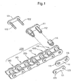
- FIG. 1 is a perspective view showing a part of a chain, which is example 1 of the present invention, with exploded views of the individual components of the outer and inner links;
- FIG. 2 is a cross-sectional view taken along a plane passing through the bowed-in central axis of a bushing of the chain of FIG. 1 with the bow exaggerated;
- FIG. 3 is a plan view obtained when FIG. 2 was viewed from a direction of an arrow III;
- FIG. 4 is a cross-sectional view taken along the line IV-IV line of FIG. 2 ;
- FIG. 5 is a cross-sectional view along a pitch line of the chain in a condition when tension is applied to the chain with the bows of bowed-out surfaces exaggerated;
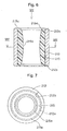
- FIG. 6 is a cross-sectional view of another embodiment of a bushing of the chain prior to its assembly taken through the central axis of the bushing;
- FIG. 7 is a plan view viewed from a direction of an arrow V11 in FIG. 6 .
- FIG. 8 is a cross-sectional view taken along the line VIII-VIII of FIG. 6 .
- FIGS. 1 to 5 A first embodiment of a chain of the present invention will be described with reference to FIGS. 1 to 5 .
- a chain 100 is composed of inner links 110 and outer links 120 such that the inner link 110 and the outer link 120 are alternately connected to each other in a large number as shown in FIG. 1 .
- the inner link 110 is composed of a pair of inner plates 111 each having two bushing holes 113.
- Two hollow cylindrical bushings 112 have both end portions press-fitted into bushing holes 113 of the pair of inner plates 111 and rotatably mount rollers 114.
- the outer link 120 is composed of a pair of outer plates 121 each having two pin holes 123, and two pins 122, both end portions of which are press-fitted into the pin holes 123 of the pair of outer plates 121.
- the inner link 110 and the outer link 120 are alternately connected to each other in a large number by fit-inserting the pins 122 into the cylindrical bushings 112 to form a length of the chain 100..
- Stainless steel is used in the bushing 112.
- the inner circumferential edge portions 112a of both end portions of the bushing 112 are chamfered.
- at least one axial groove 112b is provided on an inner circumferential surface of the bushing 112.
- four axial grooves 112b are provided on the inner circumferential surface of the bushing 112 at the equal intervals.
- the cross-sectional shape of the groove 112b is not critical. However, a V-shaped section is preferable since a resin member 115 can have protrusions 115d penetrating the entire area of the groove 112b.
- the resin member 115 is insert-molded on an inner circumferential surface of the bushing 112 so that the axial central portion of the bushing 112 is bowed out inwardly to provide a thick wall, as indicated at 115b.
- the resin member 115 is a polyetheretherketone excellent in chemical resistance and self-lubricating properties.
- the following method can be used. First, a bushing 112 having inner circumferential edge portions 112a at both ends previously-chamfered is mounted on a mold. Then, an axial central portion-slightly-diameter-reduced tsuzumi (hand drum)-shaped core is inserted into the inside of the bushing 112. Then, a resin is injected to the clearance between the inner circumferential surface of the bushing 112 and the outer circumferential surface of the tsuzumi-shaped core.
- the injected resin enters a chamfered portion at both end portions of the bushing 112, as shown in FIGS. 2 and 3 , so that the resin has flared ends 115c which embrace the opposite ends of the bushing 112.
- the tsuzumi-shaped core is removed before the resin member is cooled whereby the resin member is molded on the inner circumferential surface of the bushing 112 so that the axial central portion of the bushing 112 is bowed inwardly to provide the thick wall surface 115.
- the bow of the bowed-in surface 115b is exaggerated in the drawings.
- the flared inner circumferential edge portions 115a of both end portions of the resin member 115 are internally chamfered. This chamfering makes the insertion of the pin into the bushing 112 easy whereby cracks at end portions of the resin member 115 can be prevented.
- a hidden region denoted by a reference numeral 112a and surrounded by a solid line circle and a broken line circle, shows an inner circumferential edge portion of the chamfered bushing 112. That is the broken line circle shows an inner circumferential surface of the bushing 112.
- the resin member 115 is prevented from being displaced or shifted in the axial direction by covering chamfered portions of the bushing 112 by the flared ends 115c of the resin member 115.
- a region denoted by the reference numeral 115a and surrounded by two solid line circles shows an inner circumferential portion of the chamfered member 115.
- the innermost solid line circle shows the thickest wall portion of the resin member 115 and it also shows the inner circumferential surface of an axial central portion. It is noted that FIGS. 2 and 3 exaggeratedly show the wall thickness of the axial central portion, and an actual wall thickness (a difference between the thicknesses of the thickest portion and the thinnest portion) is about 10 to 100 im. This wall thickness is determined to be the same as the amount of deformation that is a difference between a radius at the axial central portion of the bushing and a radius of both end portions by measuring a deformation of the bushing, which is generated during an assembly of the chain, which is described later.
- the advantages obtained when the above-described bushing 112 is assembled to a chain will be described in connection with FIG. 5 .
- the bushing 112 is press-fitted into bushing holes 113 provided in inner plates 111.
- both end portions of the bushing 112 are diameter-reduced by receiving force f from the inner plate 111 so that the entire bushing 112 is deformed into a barrel shape.
- the pin 122 and the inner circumferential surface 115b of the resin member 115 come into surface contact with each other when tension F is applied to the chain so that one side contact between the pin 122 and the inner circumferential surface of the bushing 112 is suppressed. Therefore, an initial wear elongation of the chain is reduced and the wear resistance can be significantly improved.
- the chain 100 of the embodiment of FIGS. 1-5 of the present invention is chamfered in inner circumferential edge portions 112a of both end portions of the bushing 112.
- the resin member 115 is insert-molded on the inner circumferential surface of the bushing 112 so that the axial central portion becomes a thick wall, ends 115c of the resin member 115 insert-molded on the inner circumferential surface of the bushing 112 come into intimate contact with the inner circumferential edge portions 112a of the chamfered bushing 112 at both end portions of the bushing 112 and are flared toward the outside.
- ends 115c of the resin member 115 insert-molded on the inner circumferential surface of the bushing 112 come into intimate contact with the inner circumferential edge portions 112a of the chamfered bushing 112 at both end portions of the bushing 112 and are flared toward the outside.
- the bushing 112 is press-fitted into bushing holes 113 of inner plates 111 and when both end portions of the bushing 112 are diameter-reduced, the bushing 112 is bowed-out into a barrel shape.
- the inner surface of the resin member 115 becomes flat when the pin 122 and the surface of the resin member 115 come into surface contact with each other.
- One-side contact of inner circumferential edges of both end portions of the bushing 112 with the outer circumferential surface of the pin 122 is prevented so that, an initial wear elongation of the chain is reduced and the wear resistance can be significantly improved.
- the advantages are very large.
- a bushing 212 is composed of a wound bushing molded from a sheet, the ends of which are joined to form a hollow cylindrical bushing having a slit 212b at the joint.
- a resin member 215, insert-molded on an inner circumferential surface of the bushing 212 is immersion-solidified into the slit 212b of the wound bushing to produce an axially-extending outward protrusion 215d (see FIG. 8 ). Therefore, the rotation of the resin 215 in the bushing 212 is prevented so that the endurance of the chain can be improved.
- a hidden region of the bushing denoted by a reference numeral 212a and surrounded by a solid line circle and a broken line circle, shows an inner circumferential edge portion of a chamfered bushing 212. That is the broken line circle shows an inner circumferential surface of the bushing 212.
- the resin member 215 is prevented from being shifted in the axial direction by covering chamfered portions of the bushing 212 by the flared ends 215c of the resin member 215.
- a region denoted by the reference numeral 215a and surrounded by two solid line circles shows an inner circumferential portion of the chamfered member 215.
- the innermost solid line circle illustrates the thickest wall portion of the resin member 215 as determined by the inner circumferential surface 215b at an axial central portion.
- the endurance of the chain can be improved and the advantages are very large.
Landscapes
- Engineering & Computer Science (AREA)
- General Engineering & Computer Science (AREA)
- Mechanical Engineering (AREA)
- Devices For Conveying Motion By Means Of Endless Flexible Members (AREA)
- Chain Conveyers (AREA)
Applications Claiming Priority (1)
| Application Number | Priority Date | Filing Date | Title |
|---|---|---|---|
| JP2008159241A JP2010001914A (ja) | 2008-06-18 | 2008-06-18 | チェーン |
Publications (3)
| Publication Number | Publication Date |
|---|---|
| EP2136103A2 true EP2136103A2 (fr) | 2009-12-23 |
| EP2136103A3 EP2136103A3 (fr) | 2010-10-27 |
| EP2136103B1 EP2136103B1 (fr) | 2013-02-20 |
Family
ID=41066543
Family Applications (1)
| Application Number | Title | Priority Date | Filing Date |
|---|---|---|---|
| EP09003926A Active EP2136103B1 (fr) | 2008-06-18 | 2009-03-18 | Chaîne |
Country Status (4)
| Country | Link |
|---|---|
| US (1) | US8057340B2 (fr) |
| EP (1) | EP2136103B1 (fr) |
| JP (1) | JP2010001914A (fr) |
| CN (1) | CN101608680A (fr) |
Cited By (1)
| Publication number | Priority date | Publication date | Assignee | Title |
|---|---|---|---|---|
| US12595131B2 (en) | 2020-09-18 | 2026-04-07 | Gram Equipment A/S | Chain construction |
Families Citing this family (6)
| Publication number | Priority date | Publication date | Assignee | Title |
|---|---|---|---|---|
| JP2015172416A (ja) * | 2014-03-12 | 2015-10-01 | 株式会社ジェイテクト | ころ軸受 |
| JP5843917B2 (ja) | 2014-04-25 | 2016-01-13 | 株式会社椿本チエイン | チェーン |
| JP6683926B2 (ja) * | 2016-07-12 | 2020-04-22 | 株式会社椿本チエイン | ローラチェーン |
| JP6674857B2 (ja) | 2016-07-27 | 2020-04-01 | 大同工業株式会社 | チェーン及びチェーンの製造方法 |
| KR101966770B1 (ko) * | 2017-07-05 | 2019-04-19 | 주식회사 링콘테크놀로지 | 비금속 컨베이어 체인 및 그에 적용되는 스틸튜브 일체식 체인핀, 그리고 이를 포함하는 슬러지 수집기 |
| DE102020117978A1 (de) | 2020-07-08 | 2022-01-13 | Iwis Motorsysteme Gmbh & Co. Kg | Gelenkkette mit in einem Winkel angeordneten Hülsenstößen |
Citations (1)
| Publication number | Priority date | Publication date | Assignee | Title |
|---|---|---|---|---|
| JPH08309888A (ja) | 1995-03-10 | 1996-11-26 | Tsubakimoto Chain Co | 内周面に樹脂製スリーブを一体成形したブシュを有するチェーンリンク組立体の製造方法 |
Family Cites Families (11)
| Publication number | Priority date | Publication date | Assignee | Title |
|---|---|---|---|---|
| FR1381343A (fr) | 1963-09-19 | 1964-12-14 | Massey Ferguson Gmbh | Perfectionnements apportés aux garnitures de roulement notamment pour chaînes à rouleaux |
| JPS4523043Y1 (fr) * | 1965-05-26 | 1970-09-11 | ||
| JPS5553802Y2 (fr) * | 1977-02-04 | 1980-12-12 | ||
| JPS5759729Y2 (fr) * | 1978-08-30 | 1982-12-20 | ||
| JPS6256647A (ja) * | 1985-09-03 | 1987-03-12 | Tsubakimoto Chain Co | チエ−ン |
| US4926529A (en) | 1988-09-15 | 1990-05-22 | Marshall And Williams Company | Tenter frame apparatus and method |
| JP2860254B2 (ja) | 1994-06-29 | 1999-02-24 | 株式会社椿本チエイン | チェーンのリンク組立体 |
| JP4458656B2 (ja) | 2000-11-20 | 2010-04-28 | 株式会社椿本チエイン | シールチェーン |
| JP3719963B2 (ja) * | 2001-08-09 | 2005-11-24 | 株式会社椿本チエイン | チェーン |
| JP4550732B2 (ja) | 2005-12-20 | 2010-09-22 | 株式会社椿本チエイン | 固体潤滑無給油チェーン |
| JP2008133954A (ja) * | 2006-10-30 | 2008-06-12 | Ntn Corp | 弁装置用摺動部材及びこれを用いたすべり軸受 |
-
2008
- 2008-06-18 JP JP2008159241A patent/JP2010001914A/ja active Pending
-
2009
- 2009-03-17 US US12/405,562 patent/US8057340B2/en active Active
- 2009-03-18 EP EP09003926A patent/EP2136103B1/fr active Active
- 2009-05-27 CN CNA2009101452096A patent/CN101608680A/zh active Pending
Patent Citations (1)
| Publication number | Priority date | Publication date | Assignee | Title |
|---|---|---|---|---|
| JPH08309888A (ja) | 1995-03-10 | 1996-11-26 | Tsubakimoto Chain Co | 内周面に樹脂製スリーブを一体成形したブシュを有するチェーンリンク組立体の製造方法 |
Cited By (1)
| Publication number | Priority date | Publication date | Assignee | Title |
|---|---|---|---|---|
| US12595131B2 (en) | 2020-09-18 | 2026-04-07 | Gram Equipment A/S | Chain construction |
Also Published As
| Publication number | Publication date |
|---|---|
| CN101608680A (zh) | 2009-12-23 |
| EP2136103B1 (fr) | 2013-02-20 |
| JP2010001914A (ja) | 2010-01-07 |
| US8057340B2 (en) | 2011-11-15 |
| US20090318254A1 (en) | 2009-12-24 |
| EP2136103A3 (fr) | 2010-10-27 |
Similar Documents
| Publication | Publication Date | Title |
|---|---|---|
| EP2136103B1 (fr) | Chaîne | |
| US7568334B2 (en) | Pin and chain | |
| US9163378B2 (en) | Pin retainer for dragline pins | |
| US10443686B2 (en) | Chain and manufacturing method of a chain | |
| US20110068523A1 (en) | Longitudinal canted coil spring contacts to facilitate assembly | |
| US20100304906A1 (en) | Transmission chain | |
| US20140038759A1 (en) | Chain connecting pin | |
| US4250764A (en) | Non-metallic sprocket chain having quick detachable, twist-locking pivot pins | |
| US20060219529A1 (en) | Conveyor belt drive roller | |
| US7334495B2 (en) | Resin gear and rotational power transmission member of resin | |
| US20140291127A1 (en) | Chain Link Comprising an Articulation Section and a Fork Section Separated by a Slide Section | |
| US8011497B2 (en) | Seal chain having greaser | |
| US20110218068A1 (en) | Stationary guide for chain transmission | |
| JP4839264B2 (ja) | ボールねじの潤滑シール装置 | |
| DE102011085122A1 (de) | Spannvorrichtung für einen Riementrieb einer Brennkraftmaschine | |
| GB2397862A (en) | Movable guide for transmission device | |
| US20040118662A1 (en) | Curved conveyor | |
| EP3056762B1 (fr) | Unité de liaison | |
| US20120035012A1 (en) | Chain | |
| KR20090119689A (ko) | 체인 | |
| JPH0155820B2 (fr) | ||
| US20090158592A1 (en) | Method for Assembling Roller Bearing | |
| US20230313863A1 (en) | Chain | |
| EP1607656A3 (fr) | Chaîne | |
| JP7831245B2 (ja) | 継手リンク及びチェーン |
Legal Events
| Date | Code | Title | Description |
|---|---|---|---|
| PUAI | Public reference made under article 153(3) epc to a published international application that has entered the european phase |
Free format text: ORIGINAL CODE: 0009012 |
|
| AK | Designated contracting states |
Kind code of ref document: A2 Designated state(s): AT BE BG CH CY CZ DE DK EE ES FI FR GB GR HR HU IE IS IT LI LT LU LV MC MK MT NL NO PL PT RO SE SI SK TR |
|
| AX | Request for extension of the european patent |
Extension state: AL BA RS |
|
| PUAL | Search report despatched |
Free format text: ORIGINAL CODE: 0009013 |
|
| AK | Designated contracting states |
Kind code of ref document: A3 Designated state(s): AT BE BG CH CY CZ DE DK EE ES FI FR GB GR HR HU IE IS IT LI LT LU LV MC MK MT NL NO PL PT RO SE SI SK TR |
|
| AX | Request for extension of the european patent |
Extension state: AL BA RS |
|
| 17P | Request for examination filed |
Effective date: 20110111 |
|
| AKX | Designation fees paid |
Designated state(s): DE FR GB IT |
|
| GRAP | Despatch of communication of intention to grant a patent |
Free format text: ORIGINAL CODE: EPIDOSNIGR1 |
|
| GRAS | Grant fee paid |
Free format text: ORIGINAL CODE: EPIDOSNIGR3 |
|
| GRAA | (expected) grant |
Free format text: ORIGINAL CODE: 0009210 |
|
| AK | Designated contracting states |
Kind code of ref document: B1 Designated state(s): DE FR GB IT |
|
| REG | Reference to a national code |
Ref country code: GB Ref legal event code: FG4D |
|
| REG | Reference to a national code |
Ref country code: DE Ref legal event code: R096 Ref document number: 602009013371 Country of ref document: DE Effective date: 20130418 |
|
| PLBE | No opposition filed within time limit |
Free format text: ORIGINAL CODE: 0009261 |
|
| STAA | Information on the status of an ep patent application or granted ep patent |
Free format text: STATUS: NO OPPOSITION FILED WITHIN TIME LIMIT |
|
| 26N | No opposition filed |
Effective date: 20131121 |
|
| REG | Reference to a national code |
Ref country code: DE Ref legal event code: R097 Ref document number: 602009013371 Country of ref document: DE Effective date: 20131121 |
|
| REG | Reference to a national code |
Ref country code: FR Ref legal event code: PLFP Year of fee payment: 7 |
|
| PGFP | Annual fee paid to national office [announced via postgrant information from national office to epo] |
Ref country code: IT Payment date: 20150220 Year of fee payment: 7 |
|
| PGFP | Annual fee paid to national office [announced via postgrant information from national office to epo] |
Ref country code: FR Payment date: 20150309 Year of fee payment: 7 Ref country code: GB Payment date: 20150318 Year of fee payment: 7 |
|
| GBPC | Gb: european patent ceased through non-payment of renewal fee |
Effective date: 20160318 |
|
| REG | Reference to a national code |
Ref country code: FR Ref legal event code: ST Effective date: 20161130 |
|
| PG25 | Lapsed in a contracting state [announced via postgrant information from national office to epo] |
Ref country code: GB Free format text: LAPSE BECAUSE OF NON-PAYMENT OF DUE FEES Effective date: 20160318 Ref country code: FR Free format text: LAPSE BECAUSE OF NON-PAYMENT OF DUE FEES Effective date: 20160331 |
|
| PG25 | Lapsed in a contracting state [announced via postgrant information from national office to epo] |
Ref country code: IT Free format text: LAPSE BECAUSE OF NON-PAYMENT OF DUE FEES Effective date: 20160318 |
|
| PGFP | Annual fee paid to national office [announced via postgrant information from national office to epo] |
Ref country code: DE Payment date: 20260128 Year of fee payment: 18 |