EP2137484B1 - Projectile non mortel - Google Patents
Projectile non mortel Download PDFInfo
- Publication number
- EP2137484B1 EP2137484B1 EP08720065.5A EP08720065A EP2137484B1 EP 2137484 B1 EP2137484 B1 EP 2137484B1 EP 08720065 A EP08720065 A EP 08720065A EP 2137484 B1 EP2137484 B1 EP 2137484B1
- Authority
- EP
- European Patent Office
- Prior art keywords
- projectile
- impact
- target
- kinetic energy
- deformable head
- Prior art date
- Legal status (The legal status is an assumption and is not a legal conclusion. Google has not performed a legal analysis and makes no representation as to the accuracy of the status listed.)
- Ceased
Links
- 231100001160 nonlethal Toxicity 0.000 title claims description 60
- 230000007246 mechanism Effects 0.000 claims description 37
- 239000003190 viscoelastic substance Substances 0.000 claims description 4
- 229920000642 polymer Polymers 0.000 claims description 3
- 239000002994 raw material Substances 0.000 claims description 3
- 229920002379 silicone rubber Polymers 0.000 claims description 2
- 239000004945 silicone rubber Substances 0.000 claims description 2
- 239000011248 coating agent Substances 0.000 claims 1
- 238000000576 coating method Methods 0.000 claims 1
- 210000003128 head Anatomy 0.000 description 46
- 239000000463 material Substances 0.000 description 37
- 208000014674 injury Diseases 0.000 description 8
- 229920001971 elastomer Polymers 0.000 description 6
- 229920003023 plastic Polymers 0.000 description 6
- 239000004033 plastic Substances 0.000 description 6
- 208000027418 Wounds and injury Diseases 0.000 description 5
- 239000003990 capacitor Substances 0.000 description 5
- 230000006378 damage Effects 0.000 description 5
- 239000012530 fluid Substances 0.000 description 5
- 238000000034 method Methods 0.000 description 5
- 239000005060 rubber Substances 0.000 description 5
- 239000007779 soft material Substances 0.000 description 5
- 238000005452 bending Methods 0.000 description 4
- 230000009295 sperm incapacitation Effects 0.000 description 4
- 241001465754 Metazoa Species 0.000 description 3
- 239000000654 additive Substances 0.000 description 3
- 210000000887 face Anatomy 0.000 description 3
- 230000001965 increasing effect Effects 0.000 description 3
- CNQCVBJFEGMYDW-UHFFFAOYSA-N lawrencium atom Chemical compound [Lr] CNQCVBJFEGMYDW-UHFFFAOYSA-N 0.000 description 3
- 230000033001 locomotion Effects 0.000 description 3
- 239000000203 mixture Substances 0.000 description 3
- 230000008733 trauma Effects 0.000 description 3
- 229920002943 EPDM rubber Polymers 0.000 description 2
- XTXRWKRVRITETP-UHFFFAOYSA-N Vinyl acetate Chemical compound CC(=O)OC=C XTXRWKRVRITETP-UHFFFAOYSA-N 0.000 description 2
- 238000010521 absorption reaction Methods 0.000 description 2
- 239000003431 cross linking reagent Substances 0.000 description 2
- 230000007423 decrease Effects 0.000 description 2
- 230000000694 effects Effects 0.000 description 2
- 230000005489 elastic deformation Effects 0.000 description 2
- 230000002708 enhancing effect Effects 0.000 description 2
- 238000010304 firing Methods 0.000 description 2
- 230000035515 penetration Effects 0.000 description 2
- 230000002936 tranquilizing effect Effects 0.000 description 2
- RSWGJHLUYNHPMX-UHFFFAOYSA-N Abietic-Saeure Natural products C12CCC(C(C)C)=CC2=CCC2C1(C)CCCC2(C)C(O)=O RSWGJHLUYNHPMX-UHFFFAOYSA-N 0.000 description 1
- 229920000178 Acrylic resin Polymers 0.000 description 1
- 239000004925 Acrylic resin Substances 0.000 description 1
- 229920000181 Ethylene propylene rubber Polymers 0.000 description 1
- 229920000459 Nitrile rubber Polymers 0.000 description 1
- 239000005062 Polybutadiene Substances 0.000 description 1
- 229920002367 Polyisobutene Polymers 0.000 description 1
- KHPCPRHQVVSZAH-HUOMCSJISA-N Rosin Natural products O(C/C=C/c1ccccc1)[C@H]1[C@H](O)[C@@H](O)[C@@H](O)[C@@H](CO)O1 KHPCPRHQVVSZAH-HUOMCSJISA-N 0.000 description 1
- VYPSYNLAJGMNEJ-UHFFFAOYSA-N Silicium dioxide Chemical compound O=[Si]=O VYPSYNLAJGMNEJ-UHFFFAOYSA-N 0.000 description 1
- 230000002378 acidificating effect Effects 0.000 description 1
- 229920006243 acrylic copolymer Polymers 0.000 description 1
- 125000005250 alkyl acrylate group Chemical group 0.000 description 1
- DQXBYHZEEUGOBF-UHFFFAOYSA-N but-3-enoic acid;ethene Chemical compound C=C.OC(=O)CC=C DQXBYHZEEUGOBF-UHFFFAOYSA-N 0.000 description 1
- CQEYYJKEWSMYFG-UHFFFAOYSA-N butyl acrylate Chemical compound CCCCOC(=O)C=C CQEYYJKEWSMYFG-UHFFFAOYSA-N 0.000 description 1
- 230000000981 bystander Effects 0.000 description 1
- 239000008119 colloidal silica Substances 0.000 description 1
- 230000006835 compression Effects 0.000 description 1
- 238000007906 compression Methods 0.000 description 1
- 229920001577 copolymer Polymers 0.000 description 1
- 238000006073 displacement reaction Methods 0.000 description 1
- 239000003814 drug Substances 0.000 description 1
- 229940079593 drug Drugs 0.000 description 1
- 239000000806 elastomer Substances 0.000 description 1
- 230000007613 environmental effect Effects 0.000 description 1
- 239000005038 ethylene vinyl acetate Substances 0.000 description 1
- 239000000835 fiber Substances 0.000 description 1
- 229920001821 foam rubber Polymers 0.000 description 1
- 230000005484 gravity Effects 0.000 description 1
- 230000001939 inductive effect Effects 0.000 description 1
- 229910052500 inorganic mineral Inorganic materials 0.000 description 1
- 230000002452 interceptive effect Effects 0.000 description 1
- 150000002500 ions Chemical class 0.000 description 1
- 231100000225 lethality Toxicity 0.000 description 1
- 230000007774 longterm Effects 0.000 description 1
- 229920001684 low density polyethylene Polymers 0.000 description 1
- 239000004702 low-density polyethylene Substances 0.000 description 1
- 239000012528 membrane Substances 0.000 description 1
- 239000011707 mineral Substances 0.000 description 1
- 239000000178 monomer Substances 0.000 description 1
- 239000005012 oleoresinous Substances 0.000 description 1
- 230000037368 penetrate the skin Effects 0.000 description 1
- 229920001084 poly(chloroprene) Polymers 0.000 description 1
- 229920001200 poly(ethylene-vinyl acetate) Polymers 0.000 description 1
- 229920002857 polybutadiene Polymers 0.000 description 1
- 229920001083 polybutene Polymers 0.000 description 1
- 229920001748 polybutylene Polymers 0.000 description 1
- -1 polybutylenes Polymers 0.000 description 1
- 229920001195 polyisoprene Polymers 0.000 description 1
- 229920001296 polysiloxane Polymers 0.000 description 1
- 239000005077 polysulfide Substances 0.000 description 1
- 229920001021 polysulfide Polymers 0.000 description 1
- 150000008117 polysulfides Polymers 0.000 description 1
- 229920002635 polyurethane Polymers 0.000 description 1
- 239000004814 polyurethane Substances 0.000 description 1
- 239000004800 polyvinyl chloride Substances 0.000 description 1
- 229920000915 polyvinyl chloride Polymers 0.000 description 1
- 238000005381 potential energy Methods 0.000 description 1
- 239000000843 powder Substances 0.000 description 1
- 230000000241 respiratory effect Effects 0.000 description 1
- 229920006395 saturated elastomer Polymers 0.000 description 1
- 230000035939 shock Effects 0.000 description 1
- 229910052710 silicon Inorganic materials 0.000 description 1
- 239000010703 silicon Substances 0.000 description 1
- 229920006132 styrene block copolymer Polymers 0.000 description 1
- 229920003048 styrene butadiene rubber Polymers 0.000 description 1
- 229920001169 thermoplastic Polymers 0.000 description 1
- 239000004416 thermosoftening plastic Substances 0.000 description 1
- 229940125725 tranquilizer Drugs 0.000 description 1
- 239000003204 tranquilizing agent Substances 0.000 description 1
- KHPCPRHQVVSZAH-UHFFFAOYSA-N trans-cinnamyl beta-D-glucopyranoside Natural products OC1C(O)C(O)C(CO)OC1OCC=CC1=CC=CC=C1 KHPCPRHQVVSZAH-UHFFFAOYSA-N 0.000 description 1
- 125000000391 vinyl group Chemical group [H]C([*])=C([H])[H] 0.000 description 1
- 229920002554 vinyl polymer Polymers 0.000 description 1
Images




Classifications
-
- F—MECHANICAL ENGINEERING; LIGHTING; HEATING; WEAPONS; BLASTING
- F42—AMMUNITION; BLASTING
- F42B—EXPLOSIVE CHARGES, e.g. FOR BLASTING, FIREWORKS, AMMUNITION
- F42B30/00—Projectiles or missiles, not otherwise provided for, characterised by the ammunition class or type, e.g. by the launching apparatus or weapon used
- F42B30/02—Bullets
-
- F—MECHANICAL ENGINEERING; LIGHTING; HEATING; WEAPONS; BLASTING
- F42—AMMUNITION; BLASTING
- F42B—EXPLOSIVE CHARGES, e.g. FOR BLASTING, FIREWORKS, AMMUNITION
- F42B12/00—Projectiles, missiles or mines characterised by the warhead, the intended effect, or the material
- F42B12/02—Projectiles, missiles or mines characterised by the warhead, the intended effect, or the material characterised by the warhead or the intended effect
-
- F—MECHANICAL ENGINEERING; LIGHTING; HEATING; WEAPONS; BLASTING
- F42—AMMUNITION; BLASTING
- F42B—EXPLOSIVE CHARGES, e.g. FOR BLASTING, FIREWORKS, AMMUNITION
- F42B12/00—Projectiles, missiles or mines characterised by the warhead, the intended effect, or the material
- F42B12/02—Projectiles, missiles or mines characterised by the warhead, the intended effect, or the material characterised by the warhead or the intended effect
- F42B12/34—Projectiles, missiles or mines characterised by the warhead, the intended effect, or the material characterised by the warhead or the intended effect expanding before or on impact, i.e. of dumdum or mushroom type
-
- F—MECHANICAL ENGINEERING; LIGHTING; HEATING; WEAPONS; BLASTING
- F42—AMMUNITION; BLASTING
- F42B—EXPLOSIVE CHARGES, e.g. FOR BLASTING, FIREWORKS, AMMUNITION
- F42B12/00—Projectiles, missiles or mines characterised by the warhead, the intended effect, or the material
- F42B12/02—Projectiles, missiles or mines characterised by the warhead, the intended effect, or the material characterised by the warhead or the intended effect
- F42B12/36—Projectiles, missiles or mines characterised by the warhead, the intended effect, or the material characterised by the warhead or the intended effect for dispensing materials; for producing chemical or physical reaction; for signalling ; for transmitting information
-
- F—MECHANICAL ENGINEERING; LIGHTING; HEATING; WEAPONS; BLASTING
- F42—AMMUNITION; BLASTING
- F42B—EXPLOSIVE CHARGES, e.g. FOR BLASTING, FIREWORKS, AMMUNITION
- F42B12/00—Projectiles, missiles or mines characterised by the warhead, the intended effect, or the material
- F42B12/72—Projectiles, missiles or mines characterised by the warhead, the intended effect, or the material characterised by the material
-
- F—MECHANICAL ENGINEERING; LIGHTING; HEATING; WEAPONS; BLASTING
- F42—AMMUNITION; BLASTING
- F42B—EXPLOSIVE CHARGES, e.g. FOR BLASTING, FIREWORKS, AMMUNITION
- F42B12/00—Projectiles, missiles or mines characterised by the warhead, the intended effect, or the material
- F42B12/72—Projectiles, missiles or mines characterised by the warhead, the intended effect, or the material characterised by the material
- F42B12/74—Projectiles, missiles or mines characterised by the warhead, the intended effect, or the material characterised by the material of the core or solid body
-
- F—MECHANICAL ENGINEERING; LIGHTING; HEATING; WEAPONS; BLASTING
- F42—AMMUNITION; BLASTING
- F42B—EXPLOSIVE CHARGES, e.g. FOR BLASTING, FIREWORKS, AMMUNITION
- F42B8/00—Practice or training ammunition
- F42B8/12—Projectiles or missiles
Definitions
- the present invention relates to a projectile used for incapacitation of a human being or animal target and more specifically mechanisms for absorbing kinetic energy of the non-lethal projectile.
- a non-lethal weapons system is used to incapacitate as opposed to inflict injury in order to prevent suspect targets from fleeing, engaging in further combat, or committing other criminal acts.
- Conventional non-lethal weapons include billy clubs (or batons) rubber and plastic bullets. Batons as used by the law enforcement officers are wielded in close range and are capable of inflicting serious physical trauma. Rubber and plastic bullets are typically too energetic to be used at distances less than about 25 meters and become ineffective at distances greater than 50 meters. Conventional rubber and plastic bullets have caused a significant number of unwanted injuries.
- US patent 3,710,720 discloses a weapon system including a launcher and a flexible low lethality projectile of relatively large mass adapted to be radially expanded during trajectory so as to present a relatively large impact surface to the target.
- the projectile has an initial relatively small cross section so as to be insertable in a conventional launcher.
- the launcher has internal rifling grooves within the barrel to effect rotation of the projectile and radial expansion thereof due to centrifugal force.
- the relatively large area of contact on impact reduces energy per unit area penetration of the target while maintaining high inertia energy.
- US patent 6,012,295 discloses a baton projectile including a case of low density polyethylene, and a core of a soft material such as a thermoplastic gel modified rubber. At higher than acceptable impact forces, the case ruptures and the core spreads out to radially disperse the excess impact energy and to present a larger impact area to the target so that the risk of unacceptable penetration and trauma injury to the target is reduced.
- US patent 6,209,461 discloses a non-lethal projectile.
- the projectile comprises a longitudinal body having internally a longitudinal striker suitable for perforating a container of fluid under pressure in controlled manner, in particular by impact of the projectile on a target.
- the striker has an internal passage opening to the outside of the body via channels made through a rigid wall secured to the body such that the outlet offered to the fluid under pressure remains disengaged even if the impact is accompanied by the deformation of the container.
- the fluid contained in the container can thus escape and spread over the target even in such a case.
- US patent 5,698,815 discloses an electronic projectile for use with a standard cartridge. Projectile and cartridge are loaded into standard firearms and fired like a standard bullet. After leaving the barrel of a firearm, plastic sheaths and fall away and electrodes extend outward on two wires. On impact the electrodes penetrate the skin of the target making electrical contact with internal tissue of a target.
- a battery powers internal electronics to charge two output capacitors to high voltage. When the capacitors are fully charged a switch completes the circuit and discharges the capacitors through the target. Switch discharges the capacitors 20 to 100 times per second. These pulses continue for several seconds to incapacitate the target.
- the polarity of the current is changes once or twice per second to alternate between acidic and basic ions being formed around the electrodes to sterilize the puncture sight. If very-high-energy pulses are used, the switch would also discharge the capacitors several seconds after the initial stun shock to defibrillate the target. Long-term incapacitation is accomplished with a syringe filled with a tranquilizing fluid mounted within a foam rubber tip. On impact this fluid is forced into the target through a needle, with the stun effect of the electrical discharge giving the tranquilizer time to work.
- US patent 3,173,371 discloses a bullet of the expanding type which is particularly adapted for the hunting of game with high velocity firearms, expansion of the bullet being accomplished without impairing or changing, or in any manner interfering with the firing of the bullet, its passage through the barrel, or its flight characteristics. Also, to provide an expanding bullet which remains intact and does not shatter or disintegrate under conditions of impact upon either the soft or more resistant portions of game animals Further, to provide an expanding bullet which utilizes a rearward and a forward malleable core surrounded by a jacket and separated by a spreader disk having opposed conical sides which on impact cause the two cores to expand radially and flow together around the disk, thereby to form a unitary mass of relatively large diameter. Yet further, to provide an expanding bullet which is jacketed in such a manner as to exhibit externally the same appearance as a conventional jacketed bullet, and which is so arranged that its center of gravity corresponds closely to that of the conventional bullet it is intended to replace.
- target refers to the person or animal being incapacitated.
- outer as used herein referring to a non-lethal projectile includes a direction with a significant radial component pointing away from the longitudinal axis of the projectile.
- viscoelasticity describes materials that exhibit both viscous and elastic characteristics when undergoing deformation.
- energy density refers to a kinetic energy impact of a projectile on a target and is defined as the kinetic energy of the projectile divided by the area of the impact, typically given in units of area per square centimeter.
- pressure refers to the force of impact of a projectile on a target divided by the area of the impact.
- a projectile for use in a non-lethal weapon system.
- the projectile includes a main body with a longitudinal axis and a deformable head attached to the main body.
- the projectile having a certain kinetic energy is launched along the longitudinal axis in the direction of a target.
- the deformable head Upon impact of the projectile with the target, the deformable head deforms viscoelastically.
- a part of the kinetic energy of the projectile is viscously dissipated and another part of the kinetic energy is absorbed elastically so that the remaining kinetic energy of the projectile on impact with the target is reduced to a non-lethal level.
- the projectile preferably includes a semi-rigid element. which includes two or more segments connected by foldable portions.
- the semi-rigid element preferably supports at least in part the deformable head and attaches to the main body.
- An air gap and/or soft material is preferably disposed between the semi-rigid element and the main body and/or between the semi-rigid element and the deformable head.
- One or more separators are preferably embedded into the deformable head.
- the separators are preferably transversely oriented, substantially perpendicular to the longitudinal axis.
- multiple longitudinal members are embedded within the deformable head pointing towards the target and substantially parallel to the longitudinal axis.
- the longitudinal members Upon impact, the longitudinal members are bent outward away from the longitudinal axis. The bending outward by the longitudinal members preferably assists in holding the projectile to the target.
- the longitudinal members optionally include at least one barbed end which pierce and/or attach to the target upon impact.
- the deformable head is preferably formed at least in part from a silicone rubber polymer raw material without added cross linking agents or other additives.
- the projectile preferably includes a second body with the same longitudinal axis. The second body includes a hollow. The first body fits marginally within the hollow so that during the impact the first body is forced into the hollow, deforming at least one of the first body or the second body and thereby absorbing another portion of the kinetic energy.
- the projectile preferably includes an elastic mechanism which on impact absorbs elastically a portion of the kinetic energy which is stored elastically as stored energy within said elastic mechanism. After the initial impact with the target, the elastic mechanism optionally releases the stored energy to the target thus extending the impulse duration at a lower force.
- a projectile for use in a non-lethal weapon system.
- the projectile includes a first body with a longitudinal axis.
- the projectile having kinetic energy is launched substantially along the longitudinal axis in the direction of a target.
- an elastic mechanism absorbs elastically a first portion of the kinetic energy.
- the elastic mechanism preferably reduces the maximum force that the projectile exerts on the target during the impact.
- the elastic mechanism initially during the impact absorbs elastically a second portion of the kinetic energy which is stored elastically as stored energy within the elastic mechanism. After the initial impact with the target the elastic mechanism releases the stored energy to the target thus extending the duration of the impulse but at a lower force.
- a locking mechanism stores the first portion of the kinetic energy within the elastic mechanism; whereby the remaining kinetic energy of the impact is reduced to a non-lethal level of the target.
- the projectile preferably includes a deformable head attached to the first body.
- the deformable head is formed from a viscoelastic material which manifests both the elastic mechanism (with the elastic mechanical properties of the viscoelastic material) and further manifests the locking mechanism with the viscous properties of the viscoelastic material.
- the elastic mechanism preferably includes a spring which is deformed upon the impact, and stores elastically the first portion of the kinetic energy. This stored energy can be optionally delivered later to the target by releasing the locking mechanism.
- the projectile preferably includes a second body with the same longitudinal axis and a hollow. A portion of the first body fits marginally within the hollow.
- the elastic mechanism includes an elastic deformation of the first first body and/or second body while the first body is forced into the hollow during the impact.
- the first body is preferably externally ridged with first ridges and the hollow is internally ridged with matching second ridges.
- the locking mechanism includes locking the first ridges on the second ridges.
- the first ridges and second ridges are preferably shaped to prevent release of the elastic mechanism.
- the locking mechanism is performed using a frictional mechanism which dissipates another portion of the kinetic energy as energy of kinetic friction between the first body and the second body.
- a projectile including the main body, the deformable head which deforms viscoelastically, the semi-rigid element including at least two segments connected by at least one foldable portion thereof and supports at least in part the deformable head and the second body which during the impact the first body is forced into the hollow of the second body, deforming at least one of the first body or the second body and thereby absorbing a portion of the kinetic energy.
- embodiments of the present invention are applicable to projectiles fired at high speed, for example by standard weaponry, e.g. rifle, which carry sufficient kinetic energy to inflict trauma or kill. Projectiles are launched at high speed or high kinetic energy in order to achieve accuracy and range. Absorption of the energy on or just prior to impact according to aspects of the present invention to provide an accurate and non-lethal projectile.
- different embodiments of the present invention may be applied independent of the method of incapacitation used.
- the incapacitation may be inflicted by different methods including the impact of the projectile and/or by other known methods such as electric shock or administration of drugs, e.g by needle, or through the air to skin, eyes, and/or respiratory membranes of the target.
- Figure 1 is a side view of a non-lethal projectile 10, according to an embodiment of the present invention.
- Figure 1A illustrates a non-lethal projectile 10A prior to impact with a target 11 and
- Figure 1B illustrates non-lethal projectile 10B after impact with target 11.
- Non-lethal projectile 10 has a longitudinal axis labeled LA which points in the direction of propagation of projectile 10.
- a deformable head 13A is shown in Figure 1A , prior to impact with target 11 as having a diameter d and after the impact, the diameter of deformable head 13B is shown to have a larger diameter D.
- a non-limiting list of examples of base materials which may be used for deformable head 13 includes: silicones; fluorosilicones; polyurethanes; polysulfides; polybutylenes (polymers based on C 4 monomers); polyvinyl chloride; acrylic resins; vinyl acetate; ethylene vinyl acetate; vinyl acrylic (copolymers of vinyl acetate and alkyl acrylates such as butyl acrylate); styrene butadiene rubber (SBR); styrenic block copolymers; oleoresinous compositions; bituminous; rosin; unsaturated elastomers such as polybutadiene, polyisoprene and polychloroprene; saturated elastomers such as polyisobutylene, ethylene propylenediene monomer rubber (EPDM), ethylene-propylene copolymers (EPR--Ethylene Propylene rubber), nitrile-butadiene rubber, and
- the deformable material is optionally constructed of two or more layers made of different materials with different characteristics of deformability to achieve a specific behavior of deformation.
- the deformable material is optionally coated to protect the deformable material from environmental conditions or excessive forces during firing or ballistic travel.
- the material of deformable head 13 is viscoelastic and responds both viscously like putty and elastically like rubber
- the viscous deformation causes some of the kinetic energy of the impact to be dissipated and the elastic deformation allows some of the kinetic energy to be stored elastically in the material.
- the percentage of the elastic energy in the material depends on the material selected. If it is desired to reduce the bounce of the projectile from the target, elastic energy can be reduced for example to a few percent of the kinetic energy of the projectile.
- a preferred raw material used for the deformable head is Bayer Siloprene HV1/401. The material is preferably used not according to manufacturers instructions but without any cross linking agents or other additives.
- a method for making putty like elastic organo-silicon compositions, which retains shape for an extended period of time, is described in US patent 3,350,344 .
- deformable head 13 can be, by non-limiting example, conical, spheroid, cylindroid, ellipsoid, or aspheric.
- Figure 2 a top view in cross section of a non-lethal projectile 20, according to another embodiment of the present invention.
- Figure 2A illustrates non-lethal projectile 20A prior to impact with target 11
- Figure 2B illustrates non-lethal projectile 20B after impact with target 11.
- a deformable head 13A is shown in Figure 2A , prior to impact as having a diameter d and after impact, the diameter of deformable head 13B is shown to have a larger diameter D.
- the diameter D is typically 20% or 30% larger than the diameter d.
- separators 25 inserted into deformable head 13 in parallel to the desired shear flow. Separators 25 reduce the thickness of the shear layers thereby increase the force in each of the shear layers. Separators 25 are designed to have good adhesion to the deformable material so as to preferably eliminate slippage between the deformable material and separators 25 during impact. Any movement of separators 25 or bending of separators 25 during impact further reduces impact energy absorbed in target 11.
- Figure 3 a top view in cross section of a non-lethal projectile 30, according to another embodiment of the present invention.
- Figure 3A illustrates non-lethal projectile 30A prior to impact with target 11
- Figure 3B illustrates non-lethal projectile 30B after impact with target 11.
- Deformable head 13A is shown in Figure 3A , prior to impact as having a diameter d and after impact, the diameter of deformable head 13B is shown to have a larger diameter D.
- the deformable material of deformable head 13 is under pressure during impact with target 11, the deformable material flows transversely (in radial directions perpendicular to longitudinal axis LA and shear forces are developed in the material.
- Inserted through deformable head 13A are one or more longitudinal members preferably with barbs at tips 35. Inserts or barbs 35 are directed towards the target and may bend slightly outward. The pressure and shear forces on impact bend barbs 35 outward and through deformable head 13B so that barbs 35B preferably pierce, snag and/or attach the projectile to target 11 on impact.
- the elastic and/or plastic deformation, i.e. bending of inserts 35 also contribute to the absorption of energy.
- the viscous behavior of the deformable material causes the elastic energy to remain stored in bent inserts 35 and be released only after shear forces are reduced.
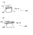
- Figure 4 a perspective view of a non-lethal projectile 40, according to an embodiment of the present invention.
- Figure 4A illustrates non-lethal projectile 40A prior to impact and
- Figure 4B illustrates non-lethal projectile 40B after impact.
- a semi- rigid support element 43 contains at least part of the deformable material of deformable head 13.
- Semi- rigid support element 43 folds outward to some degree at or near fold line 45.
- Semi-rigid support element 43 preferably folds outward due to the pressure, enhancing the outward flow of the deformable material of deformable head 13 and increasing the contact area during impact.
- semi-rigid support element 43 is bent ( Figure 4B ) by the pressure and outward shear flow of the deformable material of deformable head 13.
- semi-rigid support element 43 may be part of main body 15 or a distinct part attached thereto.
- Semi-rigid support element 43 can be continuous or partial along the perimeter of main body 15 or with variations in rigidity along the perimeter to accommodate for control the shear flow on impact of the deformable material.
- Figure 5 a side view in cross section of a non-lethal projectile 50, according to an embodiment of the present invention.
- Figure 5A illustrates non-lethal projectile 50A prior to impact and
- Figure 5B illustrates non-lethal projectile 50B at an intermediate point after impact.
- a semi- rigid support element 53 supports the deformable material of deformable head 13A.
- Semi- rigid support element 53 unfolds outward to some degree at or near fold lines or hinges 55.
- Semi-rigid support element 53 preferably unfolds outward due to the impact, enhancing the outward flow of the deformable material of deformable head 13 and increasing the contact area during impact.
- the bending or moving outward of support element 53 preferably increases the impact area by 20% or 30% or more, and thus decreases the pressure on the target.
- Air space and/or soft material 57B is of minimal volume after impact; most of the air/soft material 57A is forced to flow out by the impact.
- semi-rigid support element 53 is shown with three segments and two fold lines or hinges 55, it is readily apparent to one skilled in the art of mechanical design that similar embodiments of the present invention may be designed and constructed with semi-rigid support element 53 with one fold 55 and two segments, three folds 55 and four segments etc.
- Folds or hinges 55 can be an integral hinge or a weakened bent strip of semi-rigid support element 53 so that relatively low force causes the segments of semi-rigid support element 53 to align under impact.
- Semi-rigid support element 43 or 53 in different embodiments preferably folds elastically and/or plastically or a combination of both elastic and plastic deformation.
- FIG. 6 a side view in cross section of a non-lethal projectile 60, according to an embodiment of the present invention.
- Figure 6A illustrates non-lethal projectile 60A prior to impact and
- Figure 6B illustrates non-lethal projectile 90B after impact.
- Projectile 60 includes two main bodies 61 and 63 in which 61 is hollow and 63 fits inside only when bodies 61 and 63 elastically and/or plastically strained radially (perpendicular to the longitudinal axis LA).
- the head of non-lethal projectile 60 is not shown in Figure 6 .
- Non-lethal projectile preferably includes one or more embodiments (10, 20, 30, 40, 50) of deformable head or otherwise a conventional head.
- Non-lethal projectile 60 is launched in the direction of the arrow along longitudinal axis LA.
- body 61 On impact with target 11, body 61 is forced into body 63 by the force of the impact and the overall length (along axis LA) is reduced on impact.
- the more massive of bodies 61 and 63 is preferably in the rear, in this case body 61 is in the rear in non-lethal projectile 60.
- bodies 61 and 63 are configured with interlocking toothed ridges 65 and 67. (see detail) herein referred to simply as "teeth”.
- the ridges are formed on the inside diameter face of part 61 and on the outside diameter face of part 63 As seen in Detail, the outside diameter of part 63 is larger than the inside diameter of part 61 Also as seen best in Detail A, the teeth are preferably configured with a single sloped face and a substantially perpendicular face such that the sloped faces of the teeth of part 61 engage the sloped faces of the teeth of part 63. Therefore, as the two parts are forced together upon impact, the geometry of the teeth forces the diameter of part 61 to increase and the diameter of part 63 to decrease and thereby create radial stress. After parts 61 and 63 have reached their maximum deformation while passing over the raised teeth, they fall radially into the valley between the teeth without inducing any axial force.
- Figure 7 which includes a typical graph of force as required to displace bodies 61 relative to 63 using non-lethal projectile 60.
- Figure 8A which illustrates some of the important parameters for the design of toothed ridges 65, 67 in accordance with embodiments of the present invention. Parameters include the height H of toothed ridges 65, 67, the width P (related to number of teeth per inch) and angles a and b.
- a design of toothed ridge 65, 67 includes a slope a on one face of the ridge and the second face is substantially perpendicular as in the detail of Figure 6 . It will be understood, that the number of teeth per inch, the height of the teeth , the angles a and b and other parameters may be varied according to the needs of a specific application.
- the chosen surface materials for bodies 61 and 63 determines the friction coefficient between them.
- Figure 9 a side view in cross section of a non-lethal projectile 90, according to an embodiment of the present invention.
- Figure 9A illustrates non-lethal projectile 90A prior to impact
- Figure 9B illustrates non-lethal projectile 90B after impact.
- projectile 90 includes two main bodies 61 and 63 in which 61 is hollow and 63 fits inside.
- bodies 61, 63 are constructed to be elastically strained radially (perpendicular to the longitudinal axis LA).
- the head of non-lethal projectile 90 is not shown in Figure 9 .
- Non-lethal projectile 90 preferably includes one or more embodiments (10, 20, 30, 40, 50) of deformable head or otherwise a conventional head.
- Non-lethal projectile 90 is launched in the direction of the arrow along longitudinal axis LA.
- body 61 On impact with target 11, body 61 is forced into body 63 by the force of the impact and the overall length (along longitudinal axis LA) is reduced on impact.
- the more massive of bodies 61 and 63 is preferably in the rear, in this case body 61 is in the rear in non-lethal projectile 90.
- a spring element 93 is assembled between bodies 61 and 63. If no interlocking is applied then the potential energy in the spring is translated to additional force on the target. This force is exerted subsequently after the initial impact.
- bodies 61 and 63 are configured with interlocking toothed ridges 65 and 67.
- Non-lethal projectile 100 preferably includes one or more embodiments (10, 20, 30, 40, 50) of deformable head or otherwise a conventional head.
- a spring element 105 is assembled between parts 101 and 105.
- Body 101 is hollow and optionally body 105 marginally fits into 101 only when bodies 101 and 105 are elastically strained radially (perpendicular to the longitudinal axis LA)
- Non-lethal projectile 100 is launched in the direction of the arrow along longitudinal axis LA.
- body 105 On impact with target 11, body 105 is forced into body 101 by the force of the impact and the overall length (along longitudinal axis LA) is reduced on impact.
- the more massive of bodies 105 and 101 is preferably in the rear, in this case body 61 is in the rear in non-lethal projectile 90.
- bodies 105 and 101 are configured with interlocking toothed ridges 65 and 67.
- a spring element 103 is assembled between bodies 101 and 105. During impact of projectile 100, some of the kinetic energy of projectile 100 is stored in spring element 103 because of the forward inertia of body 101.
- a locking mechanism e.g.
- spring element 103 does not relax after compression on impact because of the action of the locking mechanism. Otherwise, if the locking mechanism is not applied, a portion of the energy stored in spring 103, transfers more energy to target 11 by pushing bodies 101,105.
Landscapes
- Engineering & Computer Science (AREA)
- General Engineering & Computer Science (AREA)
- Chemical & Material Sciences (AREA)
- Combustion & Propulsion (AREA)
- Physics & Mathematics (AREA)
- Thermal Sciences (AREA)
- Vibration Dampers (AREA)
- Aiming, Guidance, Guns With A Light Source, Armor, Camouflage, And Targets (AREA)
Claims (13)
- Projectile (10, 20, 30, 40, 50, 60, 90, 100) destiné à être utilisé avec un système d'arme non mortelle, le projectile (10, 20, 30, 40, 50, 60, 90, 100) comprenant :(a) un corps principal (15) avec un axe longitudinal (LA) ;(b) une tête déformable (13) fixée de façon fonctionnelle au corps principal (15), dans lequel le projectile (10, 20, 30, 40, 50, 60, 90, 100) est conçu de manière avoir une énergie cinétique et pour être lancé sensiblement le long dudit axe longitudinal (LA) dans la direction d'une cible, et lors de l'impact du projectile (10, 20, 30, 40, 50, 60, 90, 100) avec une cible, ladite tête déformable (13) est apte à être déformée de manière viscoélastique afin de dissiper de manière visqueuse une première partie de l'énergie cinétique et d'absorber de manière élastique une seconde partie de l'énergie cinétique, réduisant ainsi l'énergie cinétique restante du projectile (10, 20, 30, 40, 50, 60, 90, 100) sur la cible lors de l'impact à un niveau non mortel pour la cible,caractérisé en ce qu'il comprend un élément semi-rigide (43, 53), comprenant au moins deux segments reliés entre eux par au moins une portion pliable (55) de celui-ci, ledit élément semi-rigide (43, 53) supportant au moins en partie ladite tête déformable (13) et étant fixé sur le corps principal (15); et lors de l'impact du projectile (10, 20, 30, 40, 50, 60, 90, 100) sur la cible, ladite au moins une portion pliable (55) se déplace vers l'extérieur en réponse à l'impact, augmentant ainsi la surface de contact de la tête déformable (13) sur la cible.
- Projectile (10, 20, 30, 40, 50, 60, 90, 100) selon la revendication 1, comprenant en outre(d) un espace d'air (57A, 57B) entre l'élément semi-rigide (43, 53) et le corps principal (15).
- Projectile (10, 20, 30, 40, 50, 60, 90, 100) selon la revendication 1, comprenant en outre(d) au moins un séparateur (25) intégré à l'intérieur de la tête déformable (13), le séparateur (25) étant disposé sensiblement perpendiculairement à l'axe longitudinal (LA).
- Projectile (10, 20, 30, 40, 50, 60, 90, 100) selon la revendication 1, comprenant en outre(d) une pluralité d'éléments longitudinaux (35A), fixés sur le corps principal (15) et intégrés à l'intérieur de la tête déformable (15), lesdits éléments longitudinaux (35A) étant dirigés vers la cible, dans lequel lors de l'impact les éléments longitudinaux (35A) sont pliés vers l'extérieur en s'éloignant de l'axe longitudinal (LA) et percent ladite cible.
- Projectile (10, 20, 30, 40, 50, 60, 90, 100) selon la revendication 4, dans lequel les éléments longitudinaux (35A) comprennent au moins une extrémité cannelée qui lors de l'impact perce et se fixe à la cible.
- Projectile (10, 20, 30, 40, 50, 60, 90, 100) selon la revendication 1, dans lequel ladite tête déformable (13) est réalisée au moins en partie dans une matière première de polymère de caoutchouc de silicone.
- Projectile (10, 20, 30, 40, 50, 60, 90) selon la revendication 1, comprenant en outre(c) un second corps (63) avec ledit axe longitudinal (LA), ledit second corps (105, 63) comprenant une cavité, une partie du premier corps étant ajustée légèrement à l'intérieure de la cavité; et dans lequel durant l'impact ledit premier corps (61) est inséré de dans la cavité ; déformant au moins ledit premier corps (61) ou ledit second corps (105, 63) et absorbant ainsi une troisième partie de ladite énergie cinétique.
- Projectile (10, 20, 30, 40, 50, 60, 90, 100) selon la revendication 1, comprenant en outre(c) un moyen élastique (93) qui sur l'impact absorbe une troisième partie de l'énergie cinétique qui est stockée élastiquement dans le moyen élastique (93), et qui ensuite durant l'impact sur la cible libère l'énergie stockée vers la cible, prolongeant ainsi la durée d'impulsion à une force inférieure.
- Projectile (10, 20, 30, 40, 50, 60, 90, 100) selon la revendication 1, comprenant en outre(c) un revêtement sur ladite tête déformable (13).
- Projectile (10, 20, 30, 40, 50, 60, 90) destiné à être utilisé avec un système d'arme non mortelle, le projectile comprenant :(a) un premier corps (61) avec un axe longitudinal (LA), dans lequel le projectile (10, 20, 30, 40, 50, 60, 90) est conçu pour être lancé sensiblement le long de l'axe longitudinal (LA) avec une énergie cinétique dans la direction de la cible ;(b) lors de l'impact du projectile (10, 20, 30, 40, 50, 60, 90) sur la cible, un moyen élastique (93) absorbe élastiquement une première partie de l'énergie cinétique, dans lequel ledit moyen élastique comprend un ressort qui est déformé lors dudit impact, et stocke élastiquement ladite première partie de l'énergie cinétique ;(c) un mécanisme de verrouillage qui stocke ladite première partie de l'énergie cinétique dans le moyen élastique (93) ; le projectile étant caractérisé en ce que(d) un second corps (63) comprend une cavité, dans lequel une partie dudit premier corps (61) est ajustée légèrement à l'intérieur de ladite cavité, l'extérieur dudit premier corps (61) étant strié avec une pluralité de premières nervures (65) et l'intérieur de la cavité étant strié avec une pluralité de secondes nervures (67) correspondantes, et lorsque ledit premier corps (61) est introduit de force dans la cavité lors de l'impact, ledit moyen de verrouillage comprend le verrouillage desdites premières nervures (65) sur les dites secondes nervures (67), lesdites premières et secondes nervures étant configurées pour empêcher la libération dudit moyen élastique (93).
- Projectile (10, 20, 30, 40, 50, 60, 90) selon la revendication 10, dans lequel ledit moyen élastique (93) absorbe élastiquement une seconde partie de ladite énergie cinétique qui est stockée élastiquement dans le moyen élastique (93), et ensuite lors de l'impact avec la cible ledit moyen élastique (93) libère ladite énergie stockée prolongeant ainsi la durée d'impulsion à une force inférieure.
- Projectile (10, 20, 30, 40, 50, 60, 90) selon la revendication 10, comprenant en outre(e) une tête déformable (13) fixée sur ledit premier corps (61), ladite tête déformable (13) étant réalisée dans une matière viscoélastique qui présente à la fois le moyen élastique (93) et le mécanisme de verrouillage.
- Projectile (10, 20, 30, 40, 50, 60, 90) destiné à être utilisé avec un système d'arme non mortelle, le projectile (10, 20, 30, 40, 50, 60, 90) comprenant :(a) un corps principal (15) avec un axe longitudinal (LA) ;(b) une tête déformable (13) fixée de manière fonctionnelle audit corps principal (15), dans lequel le projectile (10, 20, 30, 40, 50, 60, 90) a une énergie cinétique et est lancé sensiblement le long de l'axe longitudinal (LA) dans la direction de la cible, et lors de l'impact du projectile (10, 20, 30, 40, 50, 60, 90) sur la cible, ladite tête déformable (13) déforme de manière viscoélastique, dissipant ainsi de manière visqueuse une première partie de ladite énergie cinétique et absorbant élastiquement une seconde partie de ladite énergie cinétique, réduisant ainsi l'énergie cinétique restante du projectile (10, 20, 30, 40, 50, 60, 90, 100) sur la cible lors de l'impact à un niveau non mortel pour la cible ;(c) un second corps (63) avec ledit axe longitudinal (LA), ledit second corps (63) comprenant une cavité, dans laquelle une partie dudit premier corps (61) est ajustée légèrement à l'intérieur de la cavité ; et pendant l'impact ledit premier corps (61) pénètre de force dans la cavité, déformant au moins ledit premier corps (61) ou ledit second corps (63) et absorbant ainsi une troisième partie de ladite énergie cinétique ;
le projectile étant caractérisé en ce que(d) un élément semi-rigide (43, 53) comprend au moins deux segments reliés par au moins une partie pliable de celui-ci, ledit élément semi-rigide (43, 53) supportant au moins une partie de ladite tête déformable (13) et étant fixé au corps principal (15) ; lors de l'impact du projectile (10, 20, 30, 40, 50, 60, 90) sur la cible, ladite au moins une partie pliable (53) se plie ou se courbe vers l'extérieur en réponse à l'impact.
Applications Claiming Priority (2)
| Application Number | Priority Date | Filing Date | Title |
|---|---|---|---|
| US90946107P | 2007-04-01 | 2007-04-01 | |
| PCT/IL2008/000450 WO2008120210A2 (fr) | 2007-04-01 | 2008-03-31 | Projectile non mortel |
Publications (3)
| Publication Number | Publication Date |
|---|---|
| EP2137484A2 EP2137484A2 (fr) | 2009-12-30 |
| EP2137484A4 EP2137484A4 (fr) | 2013-02-27 |
| EP2137484B1 true EP2137484B1 (fr) | 2014-11-12 |
Family
ID=39792086
Family Applications (1)
| Application Number | Title | Priority Date | Filing Date |
|---|---|---|---|
| EP08720065.5A Ceased EP2137484B1 (fr) | 2007-04-01 | 2008-03-31 | Projectile non mortel |
Country Status (6)
| Country | Link |
|---|---|
| US (2) | US7861657B2 (fr) |
| EP (1) | EP2137484B1 (fr) |
| KR (1) | KR20100016159A (fr) |
| CN (1) | CN101669008A (fr) |
| BR (1) | BRPI0808331A2 (fr) |
| WO (1) | WO2008120210A2 (fr) |
Families Citing this family (33)
| Publication number | Priority date | Publication date | Assignee | Title |
|---|---|---|---|---|
| WO2008120210A2 (fr) * | 2007-04-01 | 2008-10-09 | Sdi - Security Device International Inc. | Projectile non mortel |
| US7913626B1 (en) * | 2007-07-17 | 2011-03-29 | The United States Of America As Represented By The Secretary Of The Army | Kinetic energy absorber |
| DE102008038258B8 (de) * | 2008-08-11 | 2010-06-10 | Deutsches Zentrum für Luft- und Raumfahrt e.V. | Projektil |
| GB0817855D0 (en) * | 2008-10-01 | 2008-11-05 | Rolls Royce Plc | Artificial bird projectiles for simulating bird strike events |
| EP2646996A2 (fr) | 2010-12-01 | 2013-10-09 | Mattel, Inc. | Jeu de pâte à modeler |
| US9354026B2 (en) | 2010-12-31 | 2016-05-31 | Taser International, Inc. | Electrode for electronic weaponry that dissipates kinetic energy |
| US8896982B2 (en) | 2010-12-31 | 2014-11-25 | Taser International, Inc. | Electrodes for electronic weaponry and methods of manufacture |
| US20140109790A1 (en) * | 2011-03-30 | 2014-04-24 | Nobel Sport | Less lethal weapon projectile |
| DE102011100790A1 (de) * | 2011-05-06 | 2012-11-08 | Rheinmetall Waffe Munition Gmbh | Gummi- oder Impulsgeschoss |
| FR2988827B1 (fr) * | 2012-04-02 | 2014-11-28 | Nexter Munitions | Projectile a letalite reduite |
| US9261336B2 (en) | 2013-03-15 | 2016-02-16 | Mattel, Inc. | Toy projectile and method of making |
| US9285194B2 (en) | 2013-07-10 | 2016-03-15 | Easebon Services Limited | Foam dart having a safety cap |
| US8968126B2 (en) * | 2013-07-10 | 2015-03-03 | Easebon Services Limited | Foam dart having a safety cap |
| EP3094945B1 (fr) | 2014-01-13 | 2018-10-17 | Security Devices International, Inc. | Agencement de support de charge utile pour projectile non-létal |
| CN105180727B (zh) * | 2014-06-05 | 2017-07-11 | 赵颖 | 枪用高精度橡皮弹头 |
| FR3028309B1 (fr) * | 2014-11-06 | 2019-03-22 | Direction Generale De L'armement -Ds/Sdpa/Bpi - Dga/Ds/Sdpa/Bpi | Projectile pour les tests d'impacts d'oiseaux constitue d'un gel comportant du glycerol |
| LT3290858T (lt) * | 2015-04-30 | 2022-06-10 | Bio Ammo, S.L. | Biologiškai skaidomas šovinys, skirtas šautuvams |
| US10646763B2 (en) * | 2015-06-04 | 2020-05-12 | Riley R. Umbrell | Training bat assembly |
| KR101716684B1 (ko) | 2015-12-21 | 2017-03-16 | 대한민국 | 2액형 폴리우레탄계 점·접착 조성물 및 이를 포함하는 액상 발사체 |
| US9982976B1 (en) | 2016-11-27 | 2018-05-29 | Luke Alexander Van Valin | Paint arrow and game |
| US10018451B1 (en) * | 2017-01-10 | 2018-07-10 | Alex Brands Buzz Bee Toys (Hk) Limited | Toy dart |
| US10018452B1 (en) * | 2017-01-06 | 2018-07-10 | Alex Brands Buzz Bee Toys (Hk) Limited | Toy dart |
| US10030950B1 (en) * | 2017-10-25 | 2018-07-24 | Easebon Services Limited | Foam dart having a safety cap |
| USD872804S1 (en) | 2017-10-25 | 2020-01-14 | Easebon Services Limited | Cap of a toy dart |
| USD1077925S1 (en) | 2019-06-27 | 2025-06-03 | Easebon Services Limited | Foam dart with cap |
| USD953447S1 (en) | 2020-12-07 | 2022-05-31 | Easebon Services Limited | Cap of a toy dart |
| USD953431S1 (en) | 2020-12-07 | 2022-05-31 | Easebon Services Limited | Cap of a toy dart |
| USD953445S1 (en) | 2020-12-07 | 2022-05-31 | Easebon Services Limited | Cap of a toy dart |
| USD953446S1 (en) | 2020-12-07 | 2022-05-31 | Easebon Services Limited | Cap of a toy dart |
| USD953442S1 (en) | 2021-01-25 | 2022-05-31 | Easebon Services Limited | Cap of a toy dart |
| DE102021117140A1 (de) | 2021-07-02 | 2023-01-05 | Ruag Ammotec Gmbh | Projektil, Munition und Verfahren zum Herstellen eines Projektils |
| KR102848135B1 (ko) * | 2022-08-18 | 2025-08-20 | 광주과학기술원 | 도주 차량 추격을 위한 위치 추적 발사 부착물, 이를 충전하는 케이스 및 이를 포함하는 위치추적 시스템 |
| US12313384B2 (en) * | 2023-05-18 | 2025-05-27 | Eight Holdings LLC | Less-lethal projectiles and cartridges |
Family Cites Families (27)
| Publication number | Priority date | Publication date | Assignee | Title |
|---|---|---|---|---|
| US3173371A (en) | 1963-05-06 | 1965-03-16 | Jack C Manshel | Expanding bullet with spreader disk |
| US3350344A (en) | 1963-09-18 | 1967-10-31 | Gen Electric | Organosilicon compositions |
| US3710720A (en) | 1970-05-21 | 1973-01-16 | Mb Ass | High energy minimum lethality weapon system |
| US4008667A (en) * | 1973-12-13 | 1977-02-22 | The L.O.M. Corporation | Controlled range bullet |
| US4770423A (en) * | 1987-12-28 | 1988-09-13 | Pinske James E | Projectile for use in games |
| US5112062A (en) * | 1991-09-27 | 1992-05-12 | Seneca Sports Inc. | Safety lawn dart |
| GB9313310D0 (en) | 1993-06-28 | 1993-08-11 | Saxby Michael E | A baton projectile |
| FR2718229B1 (fr) * | 1994-03-31 | 1996-06-21 | Ruggieri | Projectile, notamment balle non létale . |
| US5698815A (en) * | 1995-12-15 | 1997-12-16 | Ragner; Gary Dean | Stun bullets |
| US5669836A (en) * | 1996-06-06 | 1997-09-23 | Hill; Jack O'neil | Arrow with marking head |
| FR2750206B1 (fr) | 1996-06-21 | 1998-09-11 | Lacroix Soc E | Projectile non letal |
| JPH11139145A (ja) * | 1997-11-04 | 1999-05-25 | Sanden Corp | 建設車両用空調装置 |
| US6189454B1 (en) | 1998-12-30 | 2001-02-20 | Gary D. Hunt | Inert practice round with solid body |
| US6315687B1 (en) * | 1999-01-06 | 2001-11-13 | Troy A. Todd | Adjustable shuttlecock |
| DE19925404C2 (de) * | 1999-06-02 | 2003-09-18 | Nico Pyrotechnik | Übungsmunition |
| US6159117A (en) * | 1999-11-24 | 2000-12-12 | T.K. Wong & Associates Ltd. | Sticky dart |
| US7086337B2 (en) * | 2000-09-28 | 2006-08-08 | Klein John M | Non-lethal projectile ammunition |
| IL147871A (en) | 2002-01-28 | 2007-12-03 | Avi Legmann | Firearm training device |
| US20050066849A1 (en) | 2003-09-29 | 2005-03-31 | Kapeles John A. | Frangible non-lethal projectile |
| US7150229B2 (en) | 2004-04-27 | 2006-12-19 | Olin Corporation | Projectile wad for ammunition cartridges |
| US20060086280A1 (en) * | 2004-06-15 | 2006-04-27 | Henri Duong | Anesthetic bullets using for guns and anesthetic weapons |
| BRPI0500226B1 (pt) | 2005-01-26 | 2017-09-12 | Condor S/A Indústria Química | Projectile for non-lethal ammunition |
| US7228802B2 (en) * | 2005-06-06 | 2007-06-12 | Vincent Montefusco | Reuseable projectile |
| US7434517B1 (en) * | 2005-11-08 | 2008-10-14 | Linker Carson R | Stun gun dart having a retractable spear |
| US20070137085A1 (en) * | 2005-12-20 | 2007-06-21 | Robert Len Aske | Safety cartridge |
| US7373887B2 (en) * | 2006-07-01 | 2008-05-20 | Jason Stewart Jackson | Expanding projectile |
| WO2008120210A2 (fr) * | 2007-04-01 | 2008-10-09 | Sdi - Security Device International Inc. | Projectile non mortel |
-
2008
- 2008-03-31 WO PCT/IL2008/000450 patent/WO2008120210A2/fr not_active Ceased
- 2008-03-31 EP EP08720065.5A patent/EP2137484B1/fr not_active Ceased
- 2008-03-31 CN CN200880010266A patent/CN101669008A/zh active Pending
- 2008-03-31 KR KR1020097022940A patent/KR20100016159A/ko not_active Ceased
- 2008-03-31 US US12/059,064 patent/US7861657B2/en active Active
- 2008-03-31 BR BRPI0808331-2A patent/BRPI0808331A2/pt not_active IP Right Cessation
-
2010
- 2010-11-23 US US12/952,335 patent/US8061276B2/en active Active
Also Published As
| Publication number | Publication date |
|---|---|
| WO2008120210A3 (fr) | 2009-04-02 |
| EP2137484A4 (fr) | 2013-02-27 |
| US7861657B2 (en) | 2011-01-04 |
| CN101669008A (zh) | 2010-03-10 |
| US20110061557A1 (en) | 2011-03-17 |
| KR20100016159A (ko) | 2010-02-12 |
| BRPI0808331A2 (pt) | 2014-07-08 |
| EP2137484A2 (fr) | 2009-12-30 |
| WO2008120210A4 (fr) | 2009-05-22 |
| US8061276B2 (en) | 2011-11-22 |
| US20080236435A1 (en) | 2008-10-02 |
| WO2008120210A2 (fr) | 2008-10-09 |
Similar Documents
| Publication | Publication Date | Title |
|---|---|---|
| EP2137484B1 (fr) | Projectile non mortel | |
| US9200878B2 (en) | Bullets with lateral damage stopping power | |
| US5698815A (en) | Stun bullets | |
| US7234399B2 (en) | Deployable bullets having high voltage electrodes | |
| US7987790B1 (en) | Ring airfoil glider expendable cartridge and glider launching method | |
| EP1228343B1 (fr) | Projectiles non mortels | |
| US6024021A (en) | Fragmenting bullet | |
| RU2758476C1 (ru) | Малокалиберная электрошоковая пуля и патрон для ее использования | |
| US6899034B1 (en) | Controlled energy release projectile | |
| WO2006111719A1 (fr) | Projectile non mortel | |
| US11287230B1 (en) | Less-than-lethal kinetic impact round | |
| WO2000002004A9 (fr) | Projectile a penetration commandee | |
| US20020152914A1 (en) | Self-destructing bullet | |
| IL201152A (en) | Projectile for the use of non-lethal weapons | |
| RU2606007C1 (ru) | Комбинированная пуля | |
| RU2788236C1 (ru) | Электрошоковая пуля, сменный ствол и оружие для их использования | |
| RU2758336C1 (ru) | Патрон стрелкового оружия с повышенным останавливающим действием | |
| RU2219477C1 (ru) | Патрон пистолетный | |
| EP1782017A1 (fr) | Munition a eclatement | |
| Tawell | Kinetic energy less lethal weapons and their associated blunt trauma injuries | |
| JP2003531351A (ja) | 火器の軟質発射体 |
Legal Events
| Date | Code | Title | Description |
|---|---|---|---|
| PUAI | Public reference made under article 153(3) epc to a published international application that has entered the european phase |
Free format text: ORIGINAL CODE: 0009012 |
|
| 17P | Request for examination filed |
Effective date: 20091030 |
|
| AK | Designated contracting states |
Kind code of ref document: A2 Designated state(s): AT BE BG CH CY CZ DE DK EE ES FI FR GB GR HR HU IE IS IT LI LT LU LV MC MT NL NO PL PT RO SE SI SK TR |
|
| DAX | Request for extension of the european patent (deleted) | ||
| A4 | Supplementary search report drawn up and despatched |
Effective date: 20130130 |
|
| RIC1 | Information provided on ipc code assigned before grant |
Ipc: F42B 12/76 20060101ALI20130123BHEP Ipc: F42B 12/34 20060101ALI20130123BHEP Ipc: F42B 8/12 20060101AFI20130123BHEP |
|
| GRAP | Despatch of communication of intention to grant a patent |
Free format text: ORIGINAL CODE: EPIDOSNIGR1 |
|
| INTG | Intention to grant announced |
Effective date: 20140211 |
|
| GRAP | Despatch of communication of intention to grant a patent |
Free format text: ORIGINAL CODE: EPIDOSNIGR1 |
|
| INTG | Intention to grant announced |
Effective date: 20140526 |
|
| GRAS | Grant fee paid |
Free format text: ORIGINAL CODE: EPIDOSNIGR3 |
|
| GRAA | (expected) grant |
Free format text: ORIGINAL CODE: 0009210 |
|
| AK | Designated contracting states |
Kind code of ref document: B1 Designated state(s): AT BE BG CH CY CZ DE DK EE ES FI FR GB GR HR HU IE IS IT LI LT LU LV MC MT NL NO PL PT RO SE SI SK TR |
|
| REG | Reference to a national code |
Ref country code: GB Ref legal event code: FG4D |
|
| REG | Reference to a national code |
Ref country code: CH Ref legal event code: EP |
|
| REG | Reference to a national code |
Ref country code: AT Ref legal event code: REF Ref document number: 696020 Country of ref document: AT Kind code of ref document: T Effective date: 20141115 |
|
| REG | Reference to a national code |
Ref country code: IE Ref legal event code: FG4D |
|
| REG | Reference to a national code |
Ref country code: DE Ref legal event code: R096 Ref document number: 602008035292 Country of ref document: DE Effective date: 20141224 |
|
| REG | Reference to a national code |
Ref country code: NL Ref legal event code: VDEP Effective date: 20141112 |
|
| REG | Reference to a national code |
Ref country code: AT Ref legal event code: MK05 Ref document number: 696020 Country of ref document: AT Kind code of ref document: T Effective date: 20141112 |
|
| PG25 | Lapsed in a contracting state [announced via postgrant information from national office to epo] |
Ref country code: ES Free format text: LAPSE BECAUSE OF FAILURE TO SUBMIT A TRANSLATION OF THE DESCRIPTION OR TO PAY THE FEE WITHIN THE PRESCRIBED TIME-LIMIT Effective date: 20141112 Ref country code: IS Free format text: LAPSE BECAUSE OF FAILURE TO SUBMIT A TRANSLATION OF THE DESCRIPTION OR TO PAY THE FEE WITHIN THE PRESCRIBED TIME-LIMIT Effective date: 20150312 Ref country code: NL Free format text: LAPSE BECAUSE OF FAILURE TO SUBMIT A TRANSLATION OF THE DESCRIPTION OR TO PAY THE FEE WITHIN THE PRESCRIBED TIME-LIMIT Effective date: 20141112 Ref country code: NO Free format text: LAPSE BECAUSE OF FAILURE TO SUBMIT A TRANSLATION OF THE DESCRIPTION OR TO PAY THE FEE WITHIN THE PRESCRIBED TIME-LIMIT Effective date: 20150212 Ref country code: PT Free format text: LAPSE BECAUSE OF FAILURE TO SUBMIT A TRANSLATION OF THE DESCRIPTION OR TO PAY THE FEE WITHIN THE PRESCRIBED TIME-LIMIT Effective date: 20150312 Ref country code: FI Free format text: LAPSE BECAUSE OF FAILURE TO SUBMIT A TRANSLATION OF THE DESCRIPTION OR TO PAY THE FEE WITHIN THE PRESCRIBED TIME-LIMIT Effective date: 20141112 Ref country code: LT Free format text: LAPSE BECAUSE OF FAILURE TO SUBMIT A TRANSLATION OF THE DESCRIPTION OR TO PAY THE FEE WITHIN THE PRESCRIBED TIME-LIMIT Effective date: 20141112 |
|
| PG25 | Lapsed in a contracting state [announced via postgrant information from national office to epo] |
Ref country code: HR Free format text: LAPSE BECAUSE OF FAILURE TO SUBMIT A TRANSLATION OF THE DESCRIPTION OR TO PAY THE FEE WITHIN THE PRESCRIBED TIME-LIMIT Effective date: 20141112 Ref country code: PL Free format text: LAPSE BECAUSE OF FAILURE TO SUBMIT A TRANSLATION OF THE DESCRIPTION OR TO PAY THE FEE WITHIN THE PRESCRIBED TIME-LIMIT Effective date: 20141112 Ref country code: AT Free format text: LAPSE BECAUSE OF FAILURE TO SUBMIT A TRANSLATION OF THE DESCRIPTION OR TO PAY THE FEE WITHIN THE PRESCRIBED TIME-LIMIT Effective date: 20141112 Ref country code: SE Free format text: LAPSE BECAUSE OF FAILURE TO SUBMIT A TRANSLATION OF THE DESCRIPTION OR TO PAY THE FEE WITHIN THE PRESCRIBED TIME-LIMIT Effective date: 20141112 Ref country code: LV Free format text: LAPSE BECAUSE OF FAILURE TO SUBMIT A TRANSLATION OF THE DESCRIPTION OR TO PAY THE FEE WITHIN THE PRESCRIBED TIME-LIMIT Effective date: 20141112 Ref country code: CY Free format text: LAPSE BECAUSE OF FAILURE TO SUBMIT A TRANSLATION OF THE DESCRIPTION OR TO PAY THE FEE WITHIN THE PRESCRIBED TIME-LIMIT Effective date: 20141112 Ref country code: GR Free format text: LAPSE BECAUSE OF FAILURE TO SUBMIT A TRANSLATION OF THE DESCRIPTION OR TO PAY THE FEE WITHIN THE PRESCRIBED TIME-LIMIT Effective date: 20150213 |
|
| PG25 | Lapsed in a contracting state [announced via postgrant information from national office to epo] |
Ref country code: CZ Free format text: LAPSE BECAUSE OF FAILURE TO SUBMIT A TRANSLATION OF THE DESCRIPTION OR TO PAY THE FEE WITHIN THE PRESCRIBED TIME-LIMIT Effective date: 20141112 Ref country code: SK Free format text: LAPSE BECAUSE OF FAILURE TO SUBMIT A TRANSLATION OF THE DESCRIPTION OR TO PAY THE FEE WITHIN THE PRESCRIBED TIME-LIMIT Effective date: 20141112 Ref country code: DK Free format text: LAPSE BECAUSE OF FAILURE TO SUBMIT A TRANSLATION OF THE DESCRIPTION OR TO PAY THE FEE WITHIN THE PRESCRIBED TIME-LIMIT Effective date: 20141112 Ref country code: RO Free format text: LAPSE BECAUSE OF FAILURE TO SUBMIT A TRANSLATION OF THE DESCRIPTION OR TO PAY THE FEE WITHIN THE PRESCRIBED TIME-LIMIT Effective date: 20141112 Ref country code: EE Free format text: LAPSE BECAUSE OF FAILURE TO SUBMIT A TRANSLATION OF THE DESCRIPTION OR TO PAY THE FEE WITHIN THE PRESCRIBED TIME-LIMIT Effective date: 20141112 |
|
| REG | Reference to a national code |
Ref country code: DE Ref legal event code: R097 Ref document number: 602008035292 Country of ref document: DE |
|
| PLBE | No opposition filed within time limit |
Free format text: ORIGINAL CODE: 0009261 |
|
| STAA | Information on the status of an ep patent application or granted ep patent |
Free format text: STATUS: NO OPPOSITION FILED WITHIN TIME LIMIT |
|
| 26N | No opposition filed |
Effective date: 20150813 |
|
| PG25 | Lapsed in a contracting state [announced via postgrant information from national office to epo] |
Ref country code: LU Free format text: LAPSE BECAUSE OF FAILURE TO SUBMIT A TRANSLATION OF THE DESCRIPTION OR TO PAY THE FEE WITHIN THE PRESCRIBED TIME-LIMIT Effective date: 20150331 Ref country code: MC Free format text: LAPSE BECAUSE OF FAILURE TO SUBMIT A TRANSLATION OF THE DESCRIPTION OR TO PAY THE FEE WITHIN THE PRESCRIBED TIME-LIMIT Effective date: 20141112 |
|
| REG | Reference to a national code |
Ref country code: CH Ref legal event code: PL |
|
| PG25 | Lapsed in a contracting state [announced via postgrant information from national office to epo] |
Ref country code: IT Free format text: LAPSE BECAUSE OF FAILURE TO SUBMIT A TRANSLATION OF THE DESCRIPTION OR TO PAY THE FEE WITHIN THE PRESCRIBED TIME-LIMIT Effective date: 20141112 |
|
| PG25 | Lapsed in a contracting state [announced via postgrant information from national office to epo] |
Ref country code: LI Free format text: LAPSE BECAUSE OF NON-PAYMENT OF DUE FEES Effective date: 20150331 Ref country code: CH Free format text: LAPSE BECAUSE OF NON-PAYMENT OF DUE FEES Effective date: 20150331 |
|
| PG25 | Lapsed in a contracting state [announced via postgrant information from national office to epo] |
Ref country code: SI Free format text: LAPSE BECAUSE OF FAILURE TO SUBMIT A TRANSLATION OF THE DESCRIPTION OR TO PAY THE FEE WITHIN THE PRESCRIBED TIME-LIMIT Effective date: 20141112 |
|
| REG | Reference to a national code |
Ref country code: FR Ref legal event code: PLFP Year of fee payment: 9 |
|
| PG25 | Lapsed in a contracting state [announced via postgrant information from national office to epo] |
Ref country code: MT Free format text: LAPSE BECAUSE OF FAILURE TO SUBMIT A TRANSLATION OF THE DESCRIPTION OR TO PAY THE FEE WITHIN THE PRESCRIBED TIME-LIMIT Effective date: 20141112 |
|
| REG | Reference to a national code |
Ref country code: FR Ref legal event code: PLFP Year of fee payment: 10 |
|
| PG25 | Lapsed in a contracting state [announced via postgrant information from national office to epo] |
Ref country code: HU Free format text: LAPSE BECAUSE OF FAILURE TO SUBMIT A TRANSLATION OF THE DESCRIPTION OR TO PAY THE FEE WITHIN THE PRESCRIBED TIME-LIMIT; INVALID AB INITIO Effective date: 20080331 Ref country code: BG Free format text: LAPSE BECAUSE OF FAILURE TO SUBMIT A TRANSLATION OF THE DESCRIPTION OR TO PAY THE FEE WITHIN THE PRESCRIBED TIME-LIMIT Effective date: 20141112 |
|
| PG25 | Lapsed in a contracting state [announced via postgrant information from national office to epo] |
Ref country code: TR Free format text: LAPSE BECAUSE OF FAILURE TO SUBMIT A TRANSLATION OF THE DESCRIPTION OR TO PAY THE FEE WITHIN THE PRESCRIBED TIME-LIMIT Effective date: 20141112 |
|
| PG25 | Lapsed in a contracting state [announced via postgrant information from national office to epo] |
Ref country code: BE Free format text: LAPSE BECAUSE OF FAILURE TO SUBMIT A TRANSLATION OF THE DESCRIPTION OR TO PAY THE FEE WITHIN THE PRESCRIBED TIME-LIMIT Effective date: 20141112 |
|
| REG | Reference to a national code |
Ref country code: FR Ref legal event code: PLFP Year of fee payment: 11 |
|
| PGFP | Annual fee paid to national office [announced via postgrant information from national office to epo] |
Ref country code: GB Payment date: 20180327 Year of fee payment: 11 Ref country code: DE Payment date: 20180328 Year of fee payment: 11 |
|
| PGFP | Annual fee paid to national office [announced via postgrant information from national office to epo] |
Ref country code: IE Payment date: 20180327 Year of fee payment: 11 Ref country code: FR Payment date: 20180330 Year of fee payment: 11 |
|
| REG | Reference to a national code |
Ref country code: DE Ref legal event code: R119 Ref document number: 602008035292 Country of ref document: DE |
|
| GBPC | Gb: european patent ceased through non-payment of renewal fee |
Effective date: 20190331 |
|
| PG25 | Lapsed in a contracting state [announced via postgrant information from national office to epo] |
Ref country code: DE Free format text: LAPSE BECAUSE OF NON-PAYMENT OF DUE FEES Effective date: 20191001 Ref country code: GB Free format text: LAPSE BECAUSE OF NON-PAYMENT OF DUE FEES Effective date: 20190331 Ref country code: IE Free format text: LAPSE BECAUSE OF NON-PAYMENT OF DUE FEES Effective date: 20190331 |
|
| PG25 | Lapsed in a contracting state [announced via postgrant information from national office to epo] |
Ref country code: FR Free format text: LAPSE BECAUSE OF NON-PAYMENT OF DUE FEES Effective date: 20190331 |