EP2138620A1 - Machine à coudre et procédé de fonctionnement d'une telle machine à coudre - Google Patents
Machine à coudre et procédé de fonctionnement d'une telle machine à coudre Download PDFInfo
- Publication number
- EP2138620A1 EP2138620A1 EP09007123A EP09007123A EP2138620A1 EP 2138620 A1 EP2138620 A1 EP 2138620A1 EP 09007123 A EP09007123 A EP 09007123A EP 09007123 A EP09007123 A EP 09007123A EP 2138620 A1 EP2138620 A1 EP 2138620A1
- Authority
- EP
- European Patent Office
- Prior art keywords
- fabric
- sewing machine
- pressure
- pressing rod
- servomotor
- Prior art date
- Legal status (The legal status is an assumption and is not a legal conclusion. Google has not performed a legal analysis and makes no representation as to the accuracy of the status listed.)
- Granted
Links
Images


Classifications
-
- D—TEXTILES; PAPER
- D05—SEWING; EMBROIDERING; TUFTING
- D05B—SEWING
- D05B27/00—Work-feeding means
- D05B27/24—Feed-dog lifting and lowering devices
-
- D—TEXTILES; PAPER
- D05—SEWING; EMBROIDERING; TUFTING
- D05B—SEWING
- D05B29/00—Pressers; Presser feet
-
- D—TEXTILES; PAPER
- D05—SEWING; EMBROIDERING; TUFTING
- D05B—SEWING
- D05B69/00—Driving-gear; Control devices
- D05B69/10—Electrical or electromagnetic drives
- D05B69/12—Electrical or electromagnetic drives using rotary electric motors
Definitions
- the invention relates to a sewing machine according to the preamble of claim 1.
- pressurization for the at least one fabric presser bar via a servomotor, in particular via a stepper motor, and a transmission lever represent a surprisingly simple design variant for flexible pressure generation on the at least one fabric presser bar.
- the pressure generation on the at least one fabric presser rod is carried out according to the invention independently of the drive of the sticherzeugungsmittel. This provides new degrees of freedom in the operation of the at least one fabric presser bar during sewing operation.
- a compressed air motor can basically be used as a servomotor.
- the servomotor can be designed as a stepper motor.
- Such a stepper motor is a cost effective variant of Servomotor according to the invention.
- a standard stepper motor can be used.
- the adaptation of the required torque for generating pressure on the at least one Stoffd Wegerstange to the output torque of the motor can be done by means of a corresponding deflection of the transmission lever.
- the adaptation of the required torque can also be done by a corresponding control of the stepper motor.
- the control of the stepper motor can be done programmatically.
- a driver according to claim 2 in addition to a defined via the servo motor pressure generation on the at least one fabric presser rod also for the possibility of a defined lifting of the at least one fabric presser bar.
- This can for example be used to adapt to different Nähgutdicken or for ventilating the at least one Stoffd Wegerstange.
- at least two fabric presser rods interact with corresponding drivers, an alternating operation of the two fabric presser rods is possible.
- Two fabric presser rods according to claim 3 lead to the possibility of sewing over a controlled slip difference set an arcuate seam course. An alternating operation between the two pressure-emitting devices of the two fabric presser rods is also possible.
- both pressure-generating devices according to claim 4 are designed according to the invention with a servomotor and a transmission lever, this leads to a further extension of the degrees of freedom in the operation of the sewing machine.
- Both transmission levers can with entrainment interact so that both pressure-emitting devices can also be raised.
- An arrangement according to claim 5 allows an adjacent arrangement of the two fabric presser rods, so that they can interact with the fabric without major design effort at adjacent locations.
- a revolving fabric conveyor belt according to claim 6 allows a Nähgutvorschub and / or a controlled introduction of sewing material fullness.
- a central control device allows synchronization of the Stoffd Wegerstangenbet Oberist with the Sticherzeugung.
- a flexible and programmable sequence of movement of the fabric presser bars is possible.
- the control of the at least one pressure-generating device can be carried out depending on programmed or during the sewing operation measured parameters.
- a position sensor according to claim 8 allows the measurement of a currently processed with the sewing machine Nähgutdicke. This measured value can then be used to control the sewing machine, in particular for controlling the servomotors.
- a multi-unit transmission mechanism according to claim 9 allows torque adjustment over a wide range.
- Another object of the invention is to provide operating methods that are possible with the aid of the inventive sewing machine.
- the pressure exerted on the cloth over the fabric presser bar varies during the stitch. Pressure is applied to the fabric only if this is absolutely necessary for the stitch formation. This reduces the material load and leads to the possibility of an accelerated sewing process. In addition, rotation of the fabric during sewing can be facilitated, resulting in improved fabric handling.
- a yarn tension specification according to claim 11 leads to a particularly economical sewing operation. It is also possible to set the pressure that the at least one fabric pressing rod exerts on the fabric, depending on a predetermined or measured default value.
- a multi-length-dependent stroke specification according to claim 13 takes into account a material crimp when sewing.
- the method of claim 15 allows z. B. the specification of a curved seam course.
- a sewing machine 1 has an upper arm 2 with a machine head 3, a vertical stand not shown in the drawing and a lower housing, which is commonly referred to as a base plate 4.
- the Base 4 has an upwardly projecting column 5, which is why the sewing machine 1 is also referred to as a column sewing machine.
- the sewing machine 1 can be used as a sleeve sewing machine.
- a not shown arm shaft for up and down drive a needle bar, not shown, with needle bar axis 6 is rotatably mounted.
- the drive of the arm shaft via a mounted in the arm 2 drive motor and a belt drive, both of which are not shown in the drawing.
- the needle bar carries at its lower end a needle.
- a gripper is rotatably mounted in the column 5. Sewing parts to be sewn are guided over a stitch hole plate forming the upper side of the column 5, through which the needle passes into the area of the gripper.
- the needle on the one hand and the gripper on the other hand constitute stich generating means of the sewing machine 1.
- a main sewing direction 7 (cf. Fig. 3 ) of the sewing machine 1 serve a lower feed dog assembly 8 and an upper feed slide assembly 9. Also, a feed of the workpieces in a direction opposite to the main sewing direction 7, so in particular a reverse sewing, is possible.
- the lower feed dog assembly 8 has two adjacent lower conveyor belts 10, 11, which are designed as polyurethane-coated timing belt.
- the toothed belts can also be made of an elastomer.
- the conveyor belts 10, 11 are so driven by mounted in the column 5 toothed disks 12 by a common drive 12a, that they move relative to the needle plate in the sewing direction 7 at the same speed.
- This drive 12a of the two lower conveyor belts 10, 11 is for example in the Fig. 1 shown.
- the drive 12a is a servomotor.
- an upper conveyor belt 13, 13a cooperates in each case.
- the lower conveyor belt 10 associated upper conveyor belt 13 is made wider than the lower conveyor belt 11 associated upper conveyor belt 13 a.
- the upper conveyor belts 13, 13a are each designed as a closed endless conveyor belt and also as a polyurethane-coated toothed belt or elastomeric timing belt.
- the upper conveyor belt 13 is deflected via a mounted on a presser foot 14 guide roller.
- the presser foot 14 is a pressure-emitting device of the sewing machine 1, which cooperates via the upper conveyor belt 13 with the workpieces to be sewn, ie with the material to be sewn.
- the upper conveyor belt 13 is driven via a toothed disc 16. This is driven by a belt drive servomotor 17, which is designed as a stepper motor.
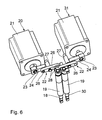
- the presser foot 14 is mounted on a first, head-side presser bar 18. This is axially guided in a Stoffstangenbuchse 19, the Machine head 3 is fixed. The presser foot 14 is fixed to the end of the first fabric presser rod 18 at the fabric side. At the opposite, machine-head-side end, the first fabric pressing rod 18 cooperates with a first pressure-generating device 20.
- This has a stepping motor designed as a servomotor 21 and as a transmission mechanism, a transmission lever 22 (see. Fig. 2 and 6 ), which is non-rotatably connected to a motor shaft 23 of the servomotor 21. Radially spaced from the motor shaft 23, the transmission lever 22 is in thrust communication with the machine head end of the first fabric presser bar 18.
- the servomotors 21 may be, in particular, standard stepper motors.
- the transmission lever 22 is a multi-part.
- a first transmission member 24 is rotatably connected to the motor shaft 23.
- the end of the radially extending transmission member 24 is articulated via a connecting joint 25 to a further transmission member 26 of the transmission lever 22.
- the further transmission member 26 is pivotable about a fixedly connected to the machine head 3 pivot joint 27.
- the connection joint 25 opposite end of the transmission member 26 is connected to a driving pin 28, which in turn is set at the machine head end of the first fabric presser rod 18.
- the driving pin 28 ensures that the first presser rod 18 is connected to the pressure-generating device 20 not only in push but also in train connection.
- a further, presser foot 29 on the side of the stand acts on the associated upper conveyor belt 13a to feed intermediate sewing material in the sewing direction 7.
- Different transport speeds of the conveyor belts 13, 13a can by use be achieved by individual toothed pulleys at the location of the toothed disc 16 with different diameters, in which case each of the upper conveyor belts 13, 13 a is associated with one of these individual toothed pulleys.
- the further presser foot 29 represents the end of the sewing material another, arm-side presser rod 30 is a machine-side end of the further fabric presser rod 30 is connected to another pressure-generating device 31 in push and pull connection.
- Dashed lines indicated symmetry plane 32 corresponds to the structure of the further pressure-generating device 31 mirror-symmetrically substantially the structure of the first pressure-generating device 20, so that only those details are explained below, in which this structure deviates from the mirror symmetry.
- the transmission member 26 of the other pressure generating means 31 is compared with the transmission member 26 of the first pressure generating device 20 with respect to the motor shaft 23 axially offset towards the interior of the machine head 3, so that the two transmission members 26 of the pressure generating means 20, 31 do not interfere with each other ,
- the transfer members 26 provide translation of the torque generated by the transfer members 24 to the cloth presser bars 18, 30.
- the second fabric pressing rod 30 is guided in a cloth bushing 19 in its axial movement.
- the two fabric presser rods 18, 30 and thus also their two machine-head-side ends are arranged directly adjacent to each other.
- the control device 33 is also in signal connection with the servomotor 12a.
- the controller 33 is connected to a in the Fig. 3 schematically indicated position sensor 34 for evaluating a current position of the arm shaft in signal connection.
- the control device 33 is in the servomotors 21 of the pressure-generating devices 20, 31 respectively integrated position sensors for evaluating a current position of the motor shafts 33 in signal communication.
- the two pressure-generating devices 20, 31 can be controlled independently of one another by the control device 33.
- a lifting movement of the driving pins 28 due to the actuation of the pressure-generating devices 20, 31 is guided via a fixed to the machine head 3 slot plate 35.
- the pressure-generating devices 20, 31 on the fabric presser bars 18, 30 exercise, ie at a given torque of the servomotors 21st , an associated rotational position of the motor shafts 23, which can be detected by the integrated position sensors of the servomotors 21.
- This thickness measurement can be used by the control device 33, for example, to specify a stitch length or a feed transport speed or a thread tension.
- the pressure exerted by the pressure-generating devices 20, 31 and thus the fabric presser bars 18, 30 on the sewing material can, controlled by the control device 33, during the execution of a stitch according to a pressure default curve, the servomotors 21 via the transmission lever 22 on the fabric presser bars 18, 30 exert to be varied.
- the foot pressure on the two fabric presser rods 18, 30 can be variably specified during a stitch. Since the servomotors 21 operate independently of the arm shaft drive, this pressure default curve can be processed synchronized to the generation of jams, but this is not mandatory. For example, at every other stitch, a pressure according to another pressure default curve or, as far as the stroke of the fabric presser bars 18, 30 is included, be exercised according to a different pressure and motion profile.
- a yarn tension of a sewing thread of the sewing machine 1 may be controlled by the controller 33, depending on the pressure exerted by the pressure generating means 20, 31. Also a pressure specification depending on a default value, in particular of the Armwellenburniere, depending on the stitch length or individually during different stitch segments is possible.
- the pressure-generating means 20, 31 can also be a stroke of the fabric presser bars 18, 30 during sewing and in particular during a stitch, individually according to a stroke-default curve, the servo motors 21 convey the fabric presser rods 18, 30 via the transmission lever 22, can be varied.
- This hub can, for. Example, to specify a via the conveyor belts 10, 11 and 13 to be created substance fullness in particular dependent on a default value can be set variably.
- the thread tension can be specified. It is also possible to set the stroke dependent on the arm shaft speed.
- the servomotors 21 can also exert a pulling action on the fabric pressing rods 18, 30 via the driving pins 28, a ventilation of the two presser feet 14, 29 is also possible.
- the control device 33 can process previously programmed processes with pressure and stroke default curves.
- control device 33 By means of a corresponding specification by the control device 33, a rapid adjustment of the lifting height which the fabric presser rods 18, 30 carry out during the sewing operation is possible.
Landscapes
- Engineering & Computer Science (AREA)
- Textile Engineering (AREA)
- Sewing Machines And Sewing (AREA)
- Physics & Mathematics (AREA)
- Electromagnetism (AREA)
- Mechanical Engineering (AREA)
Applications Claiming Priority (1)
| Application Number | Priority Date | Filing Date | Title |
|---|---|---|---|
| DE102008030797A DE102008030797A1 (de) | 2008-06-28 | 2008-06-28 | Nähmaschine sowie Verfahren zum Betrieb einer derartigen Nähmaschine |
Publications (2)
| Publication Number | Publication Date |
|---|---|
| EP2138620A1 true EP2138620A1 (fr) | 2009-12-30 |
| EP2138620B1 EP2138620B1 (fr) | 2012-05-16 |
Family
ID=41105232
Family Applications (1)
| Application Number | Title | Priority Date | Filing Date |
|---|---|---|---|
| EP20090007123 Active EP2138620B1 (fr) | 2008-06-28 | 2009-05-28 | Machine à coudre et procédé de fonctionnement d'une telle machine à coudre |
Country Status (5)
| Country | Link |
|---|---|
| EP (1) | EP2138620B1 (fr) |
| JP (1) | JP5286172B2 (fr) |
| KR (1) | KR101532097B1 (fr) |
| CN (1) | CN101613912B (fr) |
| DE (1) | DE102008030797A1 (fr) |
Cited By (3)
| Publication number | Priority date | Publication date | Assignee | Title |
|---|---|---|---|---|
| CN105316876A (zh) * | 2014-09-02 | 2016-02-10 | 保定泽泰服装机械制造有限公司 | 一种缝纫机的同步带送布机构 |
| US20240175186A1 (en) * | 2022-11-29 | 2024-05-30 | Juki Corporation | Sewing machine |
| EP4379112A1 (fr) * | 2022-11-29 | 2024-06-05 | JUKI Corporation | Machine à coudre |
Families Citing this family (10)
| Publication number | Priority date | Publication date | Assignee | Title |
|---|---|---|---|---|
| CN102953244B (zh) * | 2012-11-06 | 2015-06-17 | 贺欣机械厂股份有限公司 | 缝纫设备车缝及送料马达同步运转控制方法及装置 |
| CN103668798A (zh) * | 2013-12-19 | 2014-03-26 | 吴江市菀坪宝得利缝制设备机械厂 | 一种缝纫机上下送料机构 |
| DE102014213457A1 (de) | 2014-07-10 | 2016-01-14 | Dürkopp Adler AG | Verfahren zum Abarbeiten eines Nähprogramms zum Vernähen von Nähgut sowie die Nähmaschine hierfür |
| CN105063899B (zh) * | 2015-08-04 | 2018-01-30 | 江苏天淼软件开发有限公司 | 一种编织物自动缝合机上的卷布装置 |
| CN107488942B (zh) * | 2016-06-10 | 2022-01-07 | Juki株式会社 | 扁平缝缝纫机 |
| CN105887348B (zh) * | 2016-06-23 | 2018-07-31 | 钟治超 | 一种缝纫机送料机构 |
| DE102016011557A1 (de) * | 2016-09-26 | 2018-03-29 | Pfaff Industriesysteme Und Maschinen Gmbh | Nähmaschine mit einer Pullereinrichtung |
| CN107099941B (zh) * | 2017-05-25 | 2020-04-17 | 杰克缝纫机股份有限公司 | 一种缝纫机 |
| CN107099940B (zh) * | 2017-05-25 | 2020-03-06 | 杰克缝纫机股份有限公司 | 一种缝纫机 |
| CN111379083A (zh) * | 2018-12-30 | 2020-07-07 | 浙江中捷缝纫科技有限公司 | 抬压脚装置、缝纫机以及抬压脚装置的控制方法 |
Citations (5)
| Publication number | Priority date | Publication date | Assignee | Title |
|---|---|---|---|---|
| DE8213129U1 (de) * | 1982-05-06 | 1984-08-16 | Kochs Adler Ag, 4800 Bielefeld | Naehmaschine mit einer vorschubeinrichtung fuer das zu naehende werkstueck |
| DE102004019001A1 (de) * | 2003-04-21 | 2004-12-16 | Juki Corp., Tokio/Tokyo | Differentialvorschub-Nähmaschine |
| EP1897984A2 (fr) | 2006-09-08 | 2008-03-12 | Dürkopp Adler Aktiengesellschaft | Machine à coudre |
| EP1897985A2 (fr) | 2006-09-08 | 2008-03-12 | Dürkopp Adler Aktiengesellschaft | Machine à coudre destinée à coudre deux pièces avec incorporation de l'embus |
| EP2000571A2 (fr) * | 2007-06-08 | 2008-12-10 | Dürkopp Adler Aktiengesellschaft | Machine à coudre et méthode pour la faire fonctionner |
Family Cites Families (9)
| Publication number | Priority date | Publication date | Assignee | Title |
|---|---|---|---|---|
| JPS5540136Y2 (fr) * | 1974-07-10 | 1980-09-19 | ||
| JPH05192464A (ja) * | 1992-01-20 | 1993-08-03 | Tokai Ind Sewing Mach Co Ltd | ミシンの布押え駆動装置 |
| JP2001198373A (ja) * | 2000-01-20 | 2001-07-24 | Hirose Mfg Co Ltd | ミシンの送り装置 |
| DE10216810A1 (de) * | 2002-04-16 | 2003-11-06 | Duerkopp Adler Ag | Knopfloch-Nähmaschine |
| DE10233017B4 (de) * | 2002-07-20 | 2004-09-30 | Dürkopp Adler AG | Augen-Knopfloch-Nähmaschine |
| JP3903011B2 (ja) * | 2003-01-23 | 2007-04-11 | 株式会社廣瀬製作所 | 先引きローラ |
| JP2005192620A (ja) * | 2003-12-26 | 2005-07-21 | Juki Corp | ミシンの布送り機構 |
| DE102005049771A1 (de) * | 2005-10-18 | 2007-04-19 | Dürkopp Adler AG | Nähmaschine |
| JP2009089833A (ja) * | 2007-10-05 | 2009-04-30 | Juki Corp | ミシンの布送り装置 |
-
2008
- 2008-06-28 DE DE102008030797A patent/DE102008030797A1/de not_active Withdrawn
-
2009
- 2009-05-28 EP EP20090007123 patent/EP2138620B1/fr active Active
- 2009-06-24 KR KR1020090056429A patent/KR101532097B1/ko active Active
- 2009-06-24 JP JP2009149852A patent/JP5286172B2/ja active Active
- 2009-06-26 CN CN200910149196XA patent/CN101613912B/zh active Active
Patent Citations (5)
| Publication number | Priority date | Publication date | Assignee | Title |
|---|---|---|---|---|
| DE8213129U1 (de) * | 1982-05-06 | 1984-08-16 | Kochs Adler Ag, 4800 Bielefeld | Naehmaschine mit einer vorschubeinrichtung fuer das zu naehende werkstueck |
| DE102004019001A1 (de) * | 2003-04-21 | 2004-12-16 | Juki Corp., Tokio/Tokyo | Differentialvorschub-Nähmaschine |
| EP1897984A2 (fr) | 2006-09-08 | 2008-03-12 | Dürkopp Adler Aktiengesellschaft | Machine à coudre |
| EP1897985A2 (fr) | 2006-09-08 | 2008-03-12 | Dürkopp Adler Aktiengesellschaft | Machine à coudre destinée à coudre deux pièces avec incorporation de l'embus |
| EP2000571A2 (fr) * | 2007-06-08 | 2008-12-10 | Dürkopp Adler Aktiengesellschaft | Machine à coudre et méthode pour la faire fonctionner |
Cited By (4)
| Publication number | Priority date | Publication date | Assignee | Title |
|---|---|---|---|---|
| CN105316876A (zh) * | 2014-09-02 | 2016-02-10 | 保定泽泰服装机械制造有限公司 | 一种缝纫机的同步带送布机构 |
| US20240175186A1 (en) * | 2022-11-29 | 2024-05-30 | Juki Corporation | Sewing machine |
| EP4379112A1 (fr) * | 2022-11-29 | 2024-06-05 | JUKI Corporation | Machine à coudre |
| US12351962B2 (en) * | 2022-11-29 | 2025-07-08 | Juki Corporation | Sewing machine |
Also Published As
| Publication number | Publication date |
|---|---|
| JP2010005403A (ja) | 2010-01-14 |
| CN101613912B (zh) | 2012-11-21 |
| CN101613912A (zh) | 2009-12-30 |
| EP2138620B1 (fr) | 2012-05-16 |
| JP5286172B2 (ja) | 2013-09-11 |
| KR20100002168A (ko) | 2010-01-06 |
| KR101532097B1 (ko) | 2015-06-26 |
| DE102008030797A1 (de) | 2009-12-31 |
Similar Documents
| Publication | Publication Date | Title |
|---|---|---|
| EP2138620B1 (fr) | Machine à coudre et procédé de fonctionnement d'une telle machine à coudre | |
| DE102017107281B4 (de) | Nähmaschine | |
| DE3832124C2 (fr) | ||
| EP2206816B1 (fr) | Machine à coudre à deux aiguilles | |
| EP1048772A1 (fr) | Dispositif et procédé pour la couture automatique | |
| EP2000571B1 (fr) | Machine à coudre et méthode pour la faire fonctionner | |
| DE19516825A1 (de) | Drahtliefervorrichtung | |
| DE4313760C2 (de) | Automatische Mehrnadel-Nähmaschine | |
| DE19610411A1 (de) | Verfahren und Vorrichtung zum Herstellen von Ärmeln | |
| EP1897984A2 (fr) | Machine à coudre | |
| DE10136543C1 (de) | Nähmaschine, insbesondere Knopfloch-Nähmaschine, mit einer Nadelfaden-Klemm- und -Schneid-Einrichtung | |
| DE3743281A1 (de) | Naehmaschine zum annaehen eines bandes | |
| EP2206817B1 (fr) | Dispositif d'entraînement de barre-aiguilles commutable | |
| DE102009004218A1 (de) | Fadenschneidvorrichtung für eine Nähmaschine | |
| EP1897985B1 (fr) | Machine à coudre destinée à coudre deux pièces avec incorporation de l'embus | |
| DE19530867A1 (de) | Verknüpfungsmechanismus | |
| DE8316282U1 (de) | Vorschubantrieb für eine Stichgruppennähmaschine | |
| DE69120238T2 (de) | Industrie-Nähmaschine, die gleichzeitig verschiedene Nähte ausführen kann | |
| DE3411177C2 (de) | Nähautomat mit einem Nähkopf mit Drehgehäuse | |
| EP4540451A1 (fr) | Installation de couture | |
| DE3348054C2 (fr) | ||
| DE2230054A1 (de) | Vorrichtung zum Herstellen von Taschen mit umgelegten Paspeln | |
| DE3830772A1 (de) | Vorrichtung zur zufuehrung von bandartigen besatzstuecken unter den drueckerfuss einer naehmaschine | |
| EP3399089B1 (fr) | Procédé de production d'une extrémité de fil de navette de couture avec une saillie prédéfinie | |
| DE4228943C1 (de) | Näheinheit zur Erzeugung einer Naht |
Legal Events
| Date | Code | Title | Description |
|---|---|---|---|
| PUAI | Public reference made under article 153(3) epc to a published international application that has entered the european phase |
Free format text: ORIGINAL CODE: 0009012 |
|
| AK | Designated contracting states |
Kind code of ref document: A1 Designated state(s): AT BE BG CH CY CZ DE DK EE ES FI FR GB GR HR HU IE IS IT LI LT LU LV MC MK MT NL NO PL PT RO SE SI SK TR |
|
| 17P | Request for examination filed |
Effective date: 20100312 |
|
| 17Q | First examination report despatched |
Effective date: 20100414 |
|
| GRAP | Despatch of communication of intention to grant a patent |
Free format text: ORIGINAL CODE: EPIDOSNIGR1 |
|
| GRAS | Grant fee paid |
Free format text: ORIGINAL CODE: EPIDOSNIGR3 |
|
| GRAA | (expected) grant |
Free format text: ORIGINAL CODE: 0009210 |
|
| AK | Designated contracting states |
Kind code of ref document: B1 Designated state(s): AT BE BG CH CY CZ DE DK EE ES FI FR GB GR HR HU IE IS IT LI LT LU LV MC MK MT NL NO PL PT RO SE SI SK TR |
|
| REG | Reference to a national code |
Ref country code: GB Ref legal event code: FG4D Free format text: NOT ENGLISH |
|
| REG | Reference to a national code |
Ref country code: CH Ref legal event code: EP |
|
| REG | Reference to a national code |
Ref country code: AT Ref legal event code: REF Ref document number: 558149 Country of ref document: AT Kind code of ref document: T Effective date: 20120615 |
|
| REG | Reference to a national code |
Ref country code: RO Ref legal event code: EPE |
|
| REG | Reference to a national code |
Ref country code: IE Ref legal event code: FG4D Free format text: LANGUAGE OF EP DOCUMENT: GERMAN |
|
| REG | Reference to a national code |
Ref country code: DE Ref legal event code: R096 Ref document number: 502009003512 Country of ref document: DE Effective date: 20120719 |
|
| REG | Reference to a national code |
Ref country code: NL Ref legal event code: VDEP Effective date: 20120516 |
|
| REG | Reference to a national code |
Ref country code: LT Ref legal event code: MG4D Effective date: 20120516 |
|
| PG25 | Lapsed in a contracting state [announced via postgrant information from national office to epo] |
Ref country code: SE Free format text: LAPSE BECAUSE OF FAILURE TO SUBMIT A TRANSLATION OF THE DESCRIPTION OR TO PAY THE FEE WITHIN THE PRESCRIBED TIME-LIMIT Effective date: 20120516 Ref country code: PL Free format text: LAPSE BECAUSE OF FAILURE TO SUBMIT A TRANSLATION OF THE DESCRIPTION OR TO PAY THE FEE WITHIN THE PRESCRIBED TIME-LIMIT Effective date: 20120516 Ref country code: IS Free format text: LAPSE BECAUSE OF FAILURE TO SUBMIT A TRANSLATION OF THE DESCRIPTION OR TO PAY THE FEE WITHIN THE PRESCRIBED TIME-LIMIT Effective date: 20120916 Ref country code: LT Free format text: LAPSE BECAUSE OF FAILURE TO SUBMIT A TRANSLATION OF THE DESCRIPTION OR TO PAY THE FEE WITHIN THE PRESCRIBED TIME-LIMIT Effective date: 20120516 Ref country code: CY Free format text: LAPSE BECAUSE OF FAILURE TO SUBMIT A TRANSLATION OF THE DESCRIPTION OR TO PAY THE FEE WITHIN THE PRESCRIBED TIME-LIMIT Effective date: 20120516 Ref country code: NO Free format text: LAPSE BECAUSE OF FAILURE TO SUBMIT A TRANSLATION OF THE DESCRIPTION OR TO PAY THE FEE WITHIN THE PRESCRIBED TIME-LIMIT Effective date: 20120816 Ref country code: FI Free format text: LAPSE BECAUSE OF FAILURE TO SUBMIT A TRANSLATION OF THE DESCRIPTION OR TO PAY THE FEE WITHIN THE PRESCRIBED TIME-LIMIT Effective date: 20120516 |
|
| BERE | Be: lapsed |
Owner name: DURKOPP ADLER A.G. Effective date: 20120531 |
|
| PG25 | Lapsed in a contracting state [announced via postgrant information from national office to epo] |
Ref country code: SI Free format text: LAPSE BECAUSE OF FAILURE TO SUBMIT A TRANSLATION OF THE DESCRIPTION OR TO PAY THE FEE WITHIN THE PRESCRIBED TIME-LIMIT Effective date: 20120516 Ref country code: PT Free format text: LAPSE BECAUSE OF FAILURE TO SUBMIT A TRANSLATION OF THE DESCRIPTION OR TO PAY THE FEE WITHIN THE PRESCRIBED TIME-LIMIT Effective date: 20120917 Ref country code: HR Free format text: LAPSE BECAUSE OF FAILURE TO SUBMIT A TRANSLATION OF THE DESCRIPTION OR TO PAY THE FEE WITHIN THE PRESCRIBED TIME-LIMIT Effective date: 20120516 Ref country code: LV Free format text: LAPSE BECAUSE OF FAILURE TO SUBMIT A TRANSLATION OF THE DESCRIPTION OR TO PAY THE FEE WITHIN THE PRESCRIBED TIME-LIMIT Effective date: 20120516 Ref country code: GR Free format text: LAPSE BECAUSE OF FAILURE TO SUBMIT A TRANSLATION OF THE DESCRIPTION OR TO PAY THE FEE WITHIN THE PRESCRIBED TIME-LIMIT Effective date: 20120817 |
|
| PG25 | Lapsed in a contracting state [announced via postgrant information from national office to epo] |
Ref country code: MC Free format text: LAPSE BECAUSE OF NON-PAYMENT OF DUE FEES Effective date: 20120531 |
|
| PG25 | Lapsed in a contracting state [announced via postgrant information from national office to epo] |
Ref country code: DK Free format text: LAPSE BECAUSE OF FAILURE TO SUBMIT A TRANSLATION OF THE DESCRIPTION OR TO PAY THE FEE WITHIN THE PRESCRIBED TIME-LIMIT Effective date: 20120516 Ref country code: SK Free format text: LAPSE BECAUSE OF FAILURE TO SUBMIT A TRANSLATION OF THE DESCRIPTION OR TO PAY THE FEE WITHIN THE PRESCRIBED TIME-LIMIT Effective date: 20120516 Ref country code: EE Free format text: LAPSE BECAUSE OF FAILURE TO SUBMIT A TRANSLATION OF THE DESCRIPTION OR TO PAY THE FEE WITHIN THE PRESCRIBED TIME-LIMIT Effective date: 20120516 Ref country code: NL Free format text: LAPSE BECAUSE OF FAILURE TO SUBMIT A TRANSLATION OF THE DESCRIPTION OR TO PAY THE FEE WITHIN THE PRESCRIBED TIME-LIMIT Effective date: 20120516 |
|
| REG | Reference to a national code |
Ref country code: IE Ref legal event code: MM4A |
|
| PG25 | Lapsed in a contracting state [announced via postgrant information from national office to epo] |
Ref country code: MK Free format text: LAPSE BECAUSE OF FAILURE TO SUBMIT A TRANSLATION OF THE DESCRIPTION OR TO PAY THE FEE WITHIN THE PRESCRIBED TIME-LIMIT Effective date: 20120516 Ref country code: IT Free format text: LAPSE BECAUSE OF FAILURE TO SUBMIT A TRANSLATION OF THE DESCRIPTION OR TO PAY THE FEE WITHIN THE PRESCRIBED TIME-LIMIT Effective date: 20120516 Ref country code: BE Free format text: LAPSE BECAUSE OF NON-PAYMENT OF DUE FEES Effective date: 20120531 |
|
| PLBE | No opposition filed within time limit |
Free format text: ORIGINAL CODE: 0009261 |
|
| STAA | Information on the status of an ep patent application or granted ep patent |
Free format text: STATUS: NO OPPOSITION FILED WITHIN TIME LIMIT |
|
| REG | Reference to a national code |
Ref country code: FR Ref legal event code: ST Effective date: 20130307 |
|
| 26N | No opposition filed |
Effective date: 20130219 |
|
| PG25 | Lapsed in a contracting state [announced via postgrant information from national office to epo] |
Ref country code: IE Free format text: LAPSE BECAUSE OF NON-PAYMENT OF DUE FEES Effective date: 20120528 Ref country code: FR Free format text: LAPSE BECAUSE OF NON-PAYMENT OF DUE FEES Effective date: 20120716 |
|
| REG | Reference to a national code |
Ref country code: DE Ref legal event code: R097 Ref document number: 502009003512 Country of ref document: DE Effective date: 20130219 |
|
| PG25 | Lapsed in a contracting state [announced via postgrant information from national office to epo] |
Ref country code: BG Free format text: LAPSE BECAUSE OF FAILURE TO SUBMIT A TRANSLATION OF THE DESCRIPTION OR TO PAY THE FEE WITHIN THE PRESCRIBED TIME-LIMIT Effective date: 20120816 Ref country code: MT Free format text: LAPSE BECAUSE OF FAILURE TO SUBMIT A TRANSLATION OF THE DESCRIPTION OR TO PAY THE FEE WITHIN THE PRESCRIBED TIME-LIMIT Effective date: 20120516 |
|
| PG25 | Lapsed in a contracting state [announced via postgrant information from national office to epo] |
Ref country code: ES Free format text: LAPSE BECAUSE OF FAILURE TO SUBMIT A TRANSLATION OF THE DESCRIPTION OR TO PAY THE FEE WITHIN THE PRESCRIBED TIME-LIMIT Effective date: 20120827 |
|
| REG | Reference to a national code |
Ref country code: CH Ref legal event code: PL |
|
| GBPC | Gb: european patent ceased through non-payment of renewal fee |
Effective date: 20130528 |
|
| PG25 | Lapsed in a contracting state [announced via postgrant information from national office to epo] |
Ref country code: CH Free format text: LAPSE BECAUSE OF NON-PAYMENT OF DUE FEES Effective date: 20130531 Ref country code: LI Free format text: LAPSE BECAUSE OF NON-PAYMENT OF DUE FEES Effective date: 20130531 |
|
| PG25 | Lapsed in a contracting state [announced via postgrant information from national office to epo] |
Ref country code: GB Free format text: LAPSE BECAUSE OF NON-PAYMENT OF DUE FEES Effective date: 20130528 Ref country code: TR Free format text: LAPSE BECAUSE OF FAILURE TO SUBMIT A TRANSLATION OF THE DESCRIPTION OR TO PAY THE FEE WITHIN THE PRESCRIBED TIME-LIMIT Effective date: 20120516 |
|
| PG25 | Lapsed in a contracting state [announced via postgrant information from national office to epo] |
Ref country code: LU Free format text: LAPSE BECAUSE OF NON-PAYMENT OF DUE FEES Effective date: 20120528 |
|
| PG25 | Lapsed in a contracting state [announced via postgrant information from national office to epo] |
Ref country code: HU Free format text: LAPSE BECAUSE OF FAILURE TO SUBMIT A TRANSLATION OF THE DESCRIPTION OR TO PAY THE FEE WITHIN THE PRESCRIBED TIME-LIMIT Effective date: 20090528 |
|
| REG | Reference to a national code |
Ref country code: AT Ref legal event code: MM01 Ref document number: 558149 Country of ref document: AT Kind code of ref document: T Effective date: 20140528 |
|
| PG25 | Lapsed in a contracting state [announced via postgrant information from national office to epo] |
Ref country code: AT Free format text: LAPSE BECAUSE OF NON-PAYMENT OF DUE FEES Effective date: 20140528 |
|
| PGFP | Annual fee paid to national office [announced via postgrant information from national office to epo] |
Ref country code: RO Payment date: 20240523 Year of fee payment: 16 |
|
| PGFP | Annual fee paid to national office [announced via postgrant information from national office to epo] |
Ref country code: CZ Payment date: 20250515 Year of fee payment: 17 |
|
| PGFP | Annual fee paid to national office [announced via postgrant information from national office to epo] |
Ref country code: DE Payment date: 20250725 Year of fee payment: 17 |
|
| PG25 | Lapsed in a contracting state [announced via postgrant information from national office to epo] |
Ref country code: RO Free format text: LAPSE BECAUSE OF NON-PAYMENT OF DUE FEES Effective date: 20250528 |