EP2138695A2 - Zylinderblock, Verbrennungsmotor, Beförderungsvorrichtung und Verfahren zur Herstellung eines Zylinderblocks - Google Patents
Zylinderblock, Verbrennungsmotor, Beförderungsvorrichtung und Verfahren zur Herstellung eines Zylinderblocks Download PDFInfo
- Publication number
- EP2138695A2 EP2138695A2 EP09006877A EP09006877A EP2138695A2 EP 2138695 A2 EP2138695 A2 EP 2138695A2 EP 09006877 A EP09006877 A EP 09006877A EP 09006877 A EP09006877 A EP 09006877A EP 2138695 A2 EP2138695 A2 EP 2138695A2
- Authority
- EP
- European Patent Office
- Prior art keywords
- slide surface
- cylinder block
- etching
- jis
- length ratio
- Prior art date
- Legal status (The legal status is an assumption and is not a legal conclusion. Google has not performed a legal analysis and makes no representation as to the accuracy of the status listed.)
- Withdrawn
Links
- 238000002485 combustion reaction Methods 0.000 title claims description 59
- 238000004519 manufacturing process Methods 0.000 title claims description 51
- XUIMIQQOPSSXEZ-UHFFFAOYSA-N Silicon Chemical compound [Si] XUIMIQQOPSSXEZ-UHFFFAOYSA-N 0.000 claims abstract description 174
- 229910052710 silicon Inorganic materials 0.000 claims abstract description 174
- 239000010703 silicon Substances 0.000 claims abstract description 174
- 239000013078 crystal Substances 0.000 claims abstract description 123
- 229910000838 Al alloy Inorganic materials 0.000 claims abstract description 43
- 238000005530 etching Methods 0.000 claims description 125
- 238000000034 method Methods 0.000 claims description 110
- 230000008569 process Effects 0.000 claims description 99
- 238000000465 moulding Methods 0.000 claims description 33
- 239000011248 coating agent Substances 0.000 claims description 17
- 238000000576 coating method Methods 0.000 claims description 17
- 238000005498 polishing Methods 0.000 claims description 6
- 230000005496 eutectics Effects 0.000 description 53
- 238000005299 abrasion Methods 0.000 description 50
- 230000000052 comparative effect Effects 0.000 description 41
- 239000000314 lubricant Substances 0.000 description 38
- 239000003921 oil Substances 0.000 description 19
- 239000011159 matrix material Substances 0.000 description 13
- 238000000227 grinding Methods 0.000 description 12
- 230000014759 maintenance of location Effects 0.000 description 12
- 230000002829 reductive effect Effects 0.000 description 12
- 230000002093 peripheral effect Effects 0.000 description 11
- 238000011282 treatment Methods 0.000 description 11
- 238000009826 distribution Methods 0.000 description 10
- 238000001816 cooling Methods 0.000 description 9
- 230000001965 increasing effect Effects 0.000 description 9
- OAICVXFJPJFONN-UHFFFAOYSA-N Phosphorus Chemical compound [P] OAICVXFJPJFONN-UHFFFAOYSA-N 0.000 description 8
- 238000010586 diagram Methods 0.000 description 8
- 239000011574 phosphorus Substances 0.000 description 8
- 229910052698 phosphorus Inorganic materials 0.000 description 8
- 238000004880 explosion Methods 0.000 description 7
- 230000003247 decreasing effect Effects 0.000 description 6
- 238000011156 evaluation Methods 0.000 description 6
- 239000000463 material Substances 0.000 description 6
- 239000000203 mixture Substances 0.000 description 6
- 230000003746 surface roughness Effects 0.000 description 6
- OYPRJOBELJOOCE-UHFFFAOYSA-N Calcium Chemical compound [Ca] OYPRJOBELJOOCE-UHFFFAOYSA-N 0.000 description 5
- 229910000676 Si alloy Inorganic materials 0.000 description 5
- CSDREXVUYHZDNP-UHFFFAOYSA-N alumanylidynesilicon Chemical compound [Al].[Si] CSDREXVUYHZDNP-UHFFFAOYSA-N 0.000 description 5
- 239000011575 calcium Substances 0.000 description 5
- 229910052791 calcium Inorganic materials 0.000 description 5
- 238000005266 casting Methods 0.000 description 5
- 230000000694 effects Effects 0.000 description 5
- 229910045601 alloy Inorganic materials 0.000 description 4
- 239000000956 alloy Substances 0.000 description 4
- 229910052782 aluminium Inorganic materials 0.000 description 4
- XAGFODPZIPBFFR-UHFFFAOYSA-N aluminium Chemical compound [Al] XAGFODPZIPBFFR-UHFFFAOYSA-N 0.000 description 4
- 230000006378 damage Effects 0.000 description 4
- 239000007789 gas Substances 0.000 description 4
- 238000005259 measurement Methods 0.000 description 4
- 239000000155 melt Substances 0.000 description 4
- 230000036961 partial effect Effects 0.000 description 4
- 238000012360 testing method Methods 0.000 description 4
- RYGMFSIKBFXOCR-UHFFFAOYSA-N Copper Chemical compound [Cu] RYGMFSIKBFXOCR-UHFFFAOYSA-N 0.000 description 3
- HEMHJVSKTPXQMS-UHFFFAOYSA-M Sodium hydroxide Chemical compound [OH-].[Na+] HEMHJVSKTPXQMS-UHFFFAOYSA-M 0.000 description 3
- 241001422033 Thestylus Species 0.000 description 3
- 239000006061 abrasive grain Substances 0.000 description 3
- 230000032683 aging Effects 0.000 description 3
- 230000005540 biological transmission Effects 0.000 description 3
- 230000006835 compression Effects 0.000 description 3
- 238000007906 compression Methods 0.000 description 3
- 229910052802 copper Inorganic materials 0.000 description 3
- 239000010949 copper Substances 0.000 description 3
- 230000007423 decrease Effects 0.000 description 3
- 230000009467 reduction Effects 0.000 description 3
- 238000004513 sizing Methods 0.000 description 3
- 239000000243 solution Substances 0.000 description 3
- 239000000126 substance Substances 0.000 description 3
- XLYOFNOQVPJJNP-UHFFFAOYSA-N water Substances O XLYOFNOQVPJJNP-UHFFFAOYSA-N 0.000 description 3
- 239000010953 base metal Substances 0.000 description 2
- 238000010276 construction Methods 0.000 description 2
- 239000006185 dispersion Substances 0.000 description 2
- 229920002313 fluoropolymer Polymers 0.000 description 2
- 238000005242 forging Methods 0.000 description 2
- 238000007654 immersion Methods 0.000 description 2
- 230000006872 improvement Effects 0.000 description 2
- 230000007246 mechanism Effects 0.000 description 2
- 238000002844 melting Methods 0.000 description 2
- 230000008018 melting Effects 0.000 description 2
- 239000002245 particle Substances 0.000 description 2
- 238000007747 plating Methods 0.000 description 2
- 238000003825 pressing Methods 0.000 description 2
- 239000011347 resin Substances 0.000 description 2
- 229920005989 resin Polymers 0.000 description 2
- 230000000717 retained effect Effects 0.000 description 2
- 239000013585 weight reducing agent Substances 0.000 description 2
- 241000052343 Dares Species 0.000 description 1
- 239000004962 Polyamide-imide Substances 0.000 description 1
- 239000000919 ceramic Substances 0.000 description 1
- 238000003486 chemical etching Methods 0.000 description 1
- 239000000567 combustion gas Substances 0.000 description 1
- 238000007796 conventional method Methods 0.000 description 1
- 239000002826 coolant Substances 0.000 description 1
- 238000005520 cutting process Methods 0.000 description 1
- 238000004512 die casting Methods 0.000 description 1
- 230000002708 enhancing effect Effects 0.000 description 1
- 238000010304 firing Methods 0.000 description 1
- 238000010285 flame spraying Methods 0.000 description 1
- 239000000446 fuel Substances 0.000 description 1
- 239000002828 fuel tank Substances 0.000 description 1
- 238000009499 grossing Methods 0.000 description 1
- 238000010438 heat treatment Methods 0.000 description 1
- -1 i.e. Chemical compound 0.000 description 1
- 229910052738 indium Inorganic materials 0.000 description 1
- 238000003754 machining Methods 0.000 description 1
- 230000000873 masking effect Effects 0.000 description 1
- 238000012986 modification Methods 0.000 description 1
- 230000004048 modification Effects 0.000 description 1
- CWQXQMHSOZUFJS-UHFFFAOYSA-N molybdenum disulfide Chemical compound S=[Mo]=S CWQXQMHSOZUFJS-UHFFFAOYSA-N 0.000 description 1
- 229910052982 molybdenum disulfide Inorganic materials 0.000 description 1
- 230000003647 oxidation Effects 0.000 description 1
- 238000007254 oxidation reaction Methods 0.000 description 1
- 229920002312 polyamide-imide Polymers 0.000 description 1
- 238000012545 processing Methods 0.000 description 1
- 230000003014 reinforcing effect Effects 0.000 description 1
- 239000006104 solid solution Substances 0.000 description 1
- 238000011179 visual inspection Methods 0.000 description 1
Images






Classifications
-
- F—MECHANICAL ENGINEERING; LIGHTING; HEATING; WEAPONS; BLASTING
- F02—COMBUSTION ENGINES; HOT-GAS OR COMBUSTION-PRODUCT ENGINE PLANTS
- F02F—CYLINDERS, PISTONS OR CASINGS, FOR COMBUSTION ENGINES; ARRANGEMENTS OF SEALINGS IN COMBUSTION ENGINES
- F02F1/00—Cylinders; Cylinder heads
- F02F1/18—Other cylinders
- F02F1/20—Other cylinders characterised by constructional features providing for lubrication
-
- F—MECHANICAL ENGINEERING; LIGHTING; HEATING; WEAPONS; BLASTING
- F05—INDEXING SCHEMES RELATING TO ENGINES OR PUMPS IN VARIOUS SUBCLASSES OF CLASSES F01-F04
- F05C—INDEXING SCHEME RELATING TO MATERIALS, MATERIAL PROPERTIES OR MATERIAL CHARACTERISTICS FOR MACHINES, ENGINES OR PUMPS OTHER THAN NON-POSITIVE-DISPLACEMENT MACHINES OR ENGINES
- F05C2201/00—Metals
- F05C2201/02—Light metals
- F05C2201/021—Aluminium
-
- F—MECHANICAL ENGINEERING; LIGHTING; HEATING; WEAPONS; BLASTING
- F05—INDEXING SCHEMES RELATING TO ENGINES OR PUMPS IN VARIOUS SUBCLASSES OF CLASSES F01-F04
- F05C—INDEXING SCHEME RELATING TO MATERIALS, MATERIAL PROPERTIES OR MATERIAL CHARACTERISTICS FOR MACHINES, ENGINES OR PUMPS OTHER THAN NON-POSITIVE-DISPLACEMENT MACHINES OR ENGINES
- F05C2201/00—Metals
- F05C2201/90—Alloys not otherwise provided for
- F05C2201/903—Aluminium alloy, e.g. AlCuMgPb F34,37
-
- F—MECHANICAL ENGINEERING; LIGHTING; HEATING; WEAPONS; BLASTING
- F05—INDEXING SCHEMES RELATING TO ENGINES OR PUMPS IN VARIOUS SUBCLASSES OF CLASSES F01-F04
- F05C—INDEXING SCHEME RELATING TO MATERIALS, MATERIAL PROPERTIES OR MATERIAL CHARACTERISTICS FOR MACHINES, ENGINES OR PUMPS OTHER THAN NON-POSITIVE-DISPLACEMENT MACHINES OR ENGINES
- F05C2203/00—Non-metallic inorganic materials
- F05C2203/06—Silicon
-
- F—MECHANICAL ENGINEERING; LIGHTING; HEATING; WEAPONS; BLASTING
- F05—INDEXING SCHEMES RELATING TO ENGINES OR PUMPS IN VARIOUS SUBCLASSES OF CLASSES F01-F04
- F05C—INDEXING SCHEME RELATING TO MATERIALS, MATERIAL PROPERTIES OR MATERIAL CHARACTERISTICS FOR MACHINES, ENGINES OR PUMPS OTHER THAN NON-POSITIVE-DISPLACEMENT MACHINES OR ENGINES
- F05C2253/00—Other material characteristics; Treatment of material
- F05C2253/08—Crystalline
Definitions
- the present invention relates to a cylinder block and a production method thereof, and in particular to a cylinder block that is made of an aluminum alloy which includes silicon and a production method thereof.
- the present invention also relates to an internal combustion engine and a transportation apparatus incorporating such an cylinder block.
- silicon crystal grains located on the slide surface will contribute to the improvement of strength and abrasion resistance.
- An example of a technique for obtaining silicon crystal grains exposed on the surface of an alloy base metal is a honing process for allowing silicon crystal grains to remain jutting (called “emboss honing").
- Japanese Patent No. 2885407 discloses a technique of performing an etching process for allowing silicon crystal grains to remain jutting on the surface of an aluminum-silicon alloy, and thereafter performing an anodic oxidation to form an oxide layer, and further flame spraying a fluoroplastic onto this oxide layer to form a fluoroplastic resin layer.
- the aluminum-alloy cylinder block may experience seizing and/or significant abrasion.
- a piston made of an aluminum alloy is used in order to achieve a further weight reduction of the entire internal combustion engine, sliding occurs between the aluminum alloy surfaces, so that there is an increased likelihood of seizing.
- the present invention has been made in view of the aforementioned problems, and an objective thereof is to provide a cylinder block having an excellent abrasion resistance and seizing resistance and having a small friction loss, as well as a production method thereof.
- a cylinder block according to the present invention is a cylinder block composed of an aluminum alloy containing silicon, comprising: a cylinder wall having a slide surface on which a piston slides; and a plurality of silicon crystal grains on the slide surface, wherein a ten point-average roughness Rz JIS of the slide surface and a load length ratio Rmr(30) of the slide surface at a cut level of 30% are larger in an upper 1/4 portion of the slide surface than in a lower 1/4 portion of the slide surface.
- the ten point-average roughness Rz JIS is 0.54 ⁇ m or more and the load length ratio Rmr (30) at a cut level of 30% is 20% or more.
- the ten point-average roughness Rz JIS is 2.0 ⁇ m or less.
- the load length ratio Rmr(30) at a cut level of 30% is 55% or less.
- the ten point-average roughness Rz JIS is less than 0.54 ⁇ m and the load length ratio Rmr(30) at a cut level of 30% is 15% or less.
- the slide surface has been subjected to an etching process.
- Another cylinder block according to the present invention is a cylinder block composed of an aluminum alloy containing silicon, comprising: a cylinder wall having a slide surface on which a piston slides; and a plurality of silicon crystal grains on the slide surface, wherein, in an upper 1/4 portion of the slide surface, a ten point-average roughness Rz JIS of the slide surface is 0.54 ⁇ m or more and a load length ratio Rmr(30) of the slide surface at a cut level of 30% is 20% or more; and a coating is provided on at least a lower 1/4 portion of the slide surface.
- the ten point-average roughness Rz JIS is 2.0 ⁇ m or less.
- the load length ratio Rmr(30) at a cut level of 30% is 55% or less.
- the plurality of silicon crystal grains include a plurality of primary crystal silicon grains and a plurality of eutectic silicon grains.
- the plurality of primary crystal silicon grains have an average crystal grain size of no less than 12 ⁇ m and no more than 50 ⁇ m.
- the plurality of eutectic silicon grains have an average crystal grain size of 7.5 ⁇ m or less.
- the plurality of silicon crystal grains have a grain size distribution having a first peak existing in a crystal grain size range of no less than 1 ⁇ m and no more than 7.5 ⁇ m and a second peak existing in a crystal grain size range of no less than 12 ⁇ m and no more than 50 ⁇ m.
- a frequency at the first peak is at least five times greater than a frequency at the second peak.
- the aluminum alloy contains: no less than 73.4 mass% and no more than 79.6 mass% of aluminum; no less than 16 mass% and no more than 22 mass% of silicon; and no less than 2.0 mass% and no more than 5.0 mass% of copper.
- the aluminum alloy contains no less than 50 mass ppm and no more than 200mass ppm of phosphorus and no more than 0.01 mass% of calcium.
- An internal combustion engine comprises: the cylinder block of the above construction; and a piston which slides while being in contact with the slide surface of the cylinder block.
- the piston is composed of an aluminum alloy.
- a transportation apparatus comprises an internal combustion engine of the above construction.
- a method for producing a cylinder block according to the present invention is a method for producing a cylinder block including a cylinder wall, the cylinder wall having a slide surface on which a piston slides, the method comprising: a step of providing a molding which is composed of an aluminum alloy containing silicon; a step of polishing a region of the surface of the molding to become the slide surface by using a hone having a grit number of # 1500 or more; and a first etching step of etching only a portion of the polished region.
- the method for producing a cylinder block according to the present invention further comprises, after the first etching step, a second etching step of etching the entire region.
- no further etching step of etching the region is performed after the first etching step.
- Another method for producing a cylinder block according to the present invention is a method for producing a cylinder block including a cylinder wall, the cylinder wall having a slide surface on which a piston slides, the method comprising: a step of providing a molding which is composed of an aluminum alloy containing silicon; a step of polishing a region of the surface of the molding to become the slide surface by using a hone having a grit number of # 1500 or more; an etching step of etching the polished region; and a step of providing a coating in only a portion of the etched region.
- the ten point-average roughness Rz JIS of the slide surface and the load length ratio Rmr(30) of the slide surface at a cut level of 30% are larger in the upper 1/4 portion of the slide surface than in the lower 1/4 portion.
- the ten point-average roughness Rz JIS is 0.54 ⁇ m or more and that the load length ratio Rmr(30) at a cut level of 30% is 20% or more.
- the ten point-average roughness Rz JIS is 2.0 ⁇ m or less in the upper 1/4 portion of the slide surface.
- the load length ratio Rmr(30) is 55% or less in the upper 1/4 portion of the slide surface.
- the ten point-average roughness Rz JIS is less than 0.54 ⁇ m and that the load length ratio Rmr(30) at a cut level of 30% is 15% or less in the lower 1/4 portion of the slide surface.
- the slide surface of the cylinder block according to the present invention typically has been subjected to an etching process (chemical etching).
- the ten point-average roughness Rz JIS is 0.54 ⁇ m or more and the load length ratio Rmr(30) at a cut level of 30% is 20% or more, and furthermore, coating is provided on at least a lower 1/4 portion of the slide surface.
- the ten point-average roughness Rz JIS is 2.0 ⁇ m or less in the upper 1/4 portion of the slide surface.
- the load length ratio Rmr(30) is 55% or less in the upper 1/4 portion of the slide surface.
- the plurality of silicon crystal grains typically include a plurality of primary crystal silicon grains and a plurality of eutectic silicon grains.
- the ten point-average roughness Rz JIS and load length ratio Rmr(30) can be sufficiently increased.
- the average crystal grain size of the plurality of primary crystal silicon grains is no less than 12 ⁇ m and no more than 50 ⁇ m, and that the average crystal grain size of the plurality of eutectic silicon grains is 7.5 ⁇ m or less.
- the plurality of silicon crystal grains have a grain size distribution having a first peak existing in a crystal grain size range of no less than 1 ⁇ m and no more than 7.5 ⁇ m and a second peak existing in a crystal grain size range of no less than 12 ⁇ m and no more than 50 ⁇ m, and it is further preferable that the frequency at the first peak is at least five times greater than the frequency at the second peak.
- the aluminum alloy contains: no less than 73.4 mass% and no more than 79.6 mass% of aluminum; no less than 16 mass% and no more than 22 mass% of silicon; and no less than 2.0 mass% and no more than 5.0 mass% of copper.
- the aluminum alloy contains no less than 50 mass ppm and no more than 200mass ppm of phosphorus, and no more than 0.01 mass% of calcium.
- the aluminum alloy contains no less than 50 mass ppm and no more than 200mass ppm of phosphorus, it is possible to reduce the tendency of the silicon crystal grains to become gigantic, thus allowing for uniform dispersion of the silicon crystal grains within the alloy.
- the calcium content in the ensuring aluminum alloy is 0.01 mass% or less, the effect of providing fine silicon crystal grains due to phosphorus is secured, and a metallurgical structure with abrasion resistance can be obtained.
- a cylinder block according to the present invention can be suitably used in the internal combustion engines for various types of transportation apparatuses, and particularly suitably used in an internal combustion engine whose piston is made of an aluminum alloy for the sake of weight reduction.
- a first etching step of etching only a portion of the polished region is performed.
- the ten point-average roughness Rz JIS and the load length ratio Rmr(30) can both be made different between the portion which is etched through the first etching step and the other portion.
- the ten point-average roughness Rz JIS and the load length ratio Rmr(30) of the slide surface can be made larger in the upper 1/4 portion than in the lower 1/4 portion, whereby a cylinder block having an excellent abrasion resistance and seizing resistance and a small friction loss can be produced.
- a second etching step of etching the entire region to become the slide surface may be performed.
- the entire slide surface will have been subjected to an etching process (although the portion which is etched through the first etching step will experience a large etching amount than will the other portion).
- recesses between silicon crystal grains which function as oil puddles for retaining the lubricant are suitably formed across the entire slide surface, thus further improving the abrasion resistance and seizing resistance of the entire slide surface.
- no further etching step of etching the region to become the slide surface may be performed after the first etching step.
- the number of steps is reduced, whereby the production cost can be reduced and the production steps can be simplified.
- the ten point-average roughness Rz JIS and the load length ratio Rmr(30) of the slide surface can be made larger in the upper 1/4 portion than in the lower 1/4 portion, whereby a cylinder block having an excellent abrasion resistance and seizing resistance and a small friction loss can be produced.
- a region of the surface of a molding to become a slide surface is polished by using a hone having a grit number of #1500 or more, and thereafter at least a portion of the polished region is etched.
- a surface is created where not only a large number of primary crystal silicon grains but also a large number of eutectic silicon grains remain jutting (protruding), and oil puddles having sufficient depths are formed with a fine pitch. Therefore, the abrasion resistance and seizing resistance in a portion of the slide surface can be significantly improved.
- a cylinder block having an excellent abrasion resistance and seizing resistance and having a small friction loss, as well as a production method thereof. Moreover, according to the present invention, an internal combustion engine and a transportation apparatus incorporating such a cylinder block are also provided.
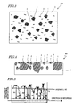
- FIG. 1 is a perspective view schematically showing a cylinder block 100 according to a preferred embodiment of the present invention.
- FIG. 2 is a cross-sectional view schematically showing a cylinder block 100 according to a preferred embodiment of the present invention.
- FIG. 3 is a plan view schematically showing an enlarged image of a slide surface of the cylinder block 100.
- FIG. 4 is a cross-sectional view schematically showing an enlarged image of a slide surface of the cylinder block 100.
- FIG. 5 is a diagram for explaining a ten point-average roughness Rz JIS .
- FIG. 6 is a diagram for explaining a load length ratio Rmr(c).
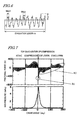
- FIG. 7 is a graph showing an exemplary relationship between a crank angle (deg) and a gas pressure (MPa) and a frictional force (N) in a conventional internal combustion engine.
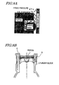
- FIGS. 8A and 8B are diagrams for explaining a reason why the frictional force acting on a slide surface becomes greatest immediately after explosion.
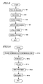
- FIG. 9 is a flowchart showing production steps for the cylinder block 100.
- FIG. 10 is a flowchart showing production steps for the cylinder block 100.
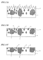
- FIGS. 11A to 11E are step-by-step cross-sectional views schematically showing, partly, the production steps for the cylinder block 100.
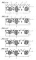
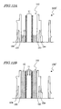
- FIGS. 12A and 12B are step-by-step cross-sectional view schematically showing, partly, the production steps for the cylinder block 100.
- FIG. 13 is a flowchart showing the production steps for the cylinder block 100.
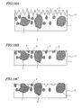
- FIG. 14 is a step cross-sectional view schematically showing a part of the production steps for the cylinder block 100.
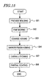
- FIG. 15 is a flowchart showing the production steps for the cylinder block 100.
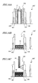
- FIGS. 16A to 16C are step-by-step cross-sectional views schematically showing, partly, the production steps for the cylinder block 100.
- FIGS. 17A to 17C are diagrams for explaining a reason why eutectic silicon grains do not contribute to lubricant retention when an emboss honing process is performed.
- FIGS. 18A to 18C are diagrams for explaining a reason why eutectic silicon grains do not contribute to lubricant retention when an etching process is performed without first performing a mirror-finish honing process.
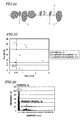
- FIG. 19 is a diagram schematically showing a scratch test machine 30 which is used for measuring a friction coefficient.
- FIG. 20 is a graph in which Examples 1 to 3 and Comparative Examples 1 to 11 are plotted, on a horizontal axis representing a ten point-average roughness Rz JIS and a vertical axis representing a load length ratio Rmr(30) at a cut level of 30%, with respect to an upper 1/4 portion of the slide surface.
- FIG. 21 is a cross-sectional view schematically showing a slide surface on which not only primary-crystal silicon grains but also eutectic silicon grains remain jutting.
- FIG. 22 is a cross-sectional view schematically showing a slide surface on which substantially nothing but primary-crystal silicon grains remain jutting.
- FIG. 23 is a diagram for explaining a reason why a constant emboss height cannot be obtained when an emboss honing process is employed.
- FIG. 24 is a diagram for explaining a reason why a constant emboss height is obtained when an etching process is employed.
- FIG. 25 is a graph in which Examples 1 to 3 and Comparative Examples 1 to 11 are plotted, on a horizontal axis representing a ten point-average roughness Rz JIS and a vertical axis representing a load length ratio Rmr(30) at a cut level of 30%, with respect to a lower 1/4 portion of the slide surface.
- FIG. 26 is a graph showing an example of a preferable grain size distribution of silicon crystal grains.
- FIG. 27 is a cross-sectional view schematically showing an internal combustion engine 150 having the cylinder block 100.
- FIG. 28 is a side view schematically showing a motorcycle incorporating the internal combustion engine 150 shown in FIG. 27 .
- FIG. 1 and FIG. 2 show a cylinder block according to the present embodiment (which may also be referred to as a "cylinder body") 100.
- FIG. 1 and FIG. 2 are a perspective view and a cross-sectional view schematically showing the cylinder block 100.
- the cylinder block 100 is made of an aluminum alloy which contains silicon, and more specifically, an aluminum-silicon alloy of a hypereutectic composition containing a large amount of silicon.
- the cylinder block 100 includes: a wall portion (referred to as a "cylinder wall”) 103 defining a cylinder bore 102; and a wall portion (referred to as a "outer wall”) 104 surrounding the cylinder wall 103 and defining the outer contour of the cylinder block 100. Between the cylinder wall 103 and the outer wall 104, a water jacket 105 for retaining a coolant is provided.
- the present embodiment illustrates a single-cylindered cylinder block 100, the cylinder block 100 may be multi-cylindered.
- a surface 101 of the cylinder wall 103 facing the cylinder bore 102 defines a slide surface on which a piston slides (i.e., the slide surface is in contact with a piston).
- the slide surface 101 is shown enlarged in FIG. 3.
- FIG. 3 is a plan view schematically showing the slide surface 101.
- the cylinder block 100 having the cylinder wall 103 having the slide surface 101 includes a plurality of silicon crystal grains 1 and 2 on the slide surface 101. These silicon crystal grains 1 and 2 are present, in a dispersed manner, in a matrix (alloy base metal) 3 of solid solution which contains aluminum.
- the silicon crystal grains which are the first to be formed when a melt of an aluminum-silicon alloy which has a hypereutectic composition are referred to as "primary-crystal silicon grains".
- the silicon crystal grains which are then formed are referred to as "eutectic silicon grains”.
- the relatively large silicon crystal grains 1 are the primary-crystal silicon grains.
- the relatively small silicon crystal grains 2 present between the primary-crystal silicon grains are the eutectic silicon grains.
- FIG. 4 shows a cross-sectional structure of the slide surface 101.
- the plurality of silicon crystal grains 1 and 2 including the primary-crystal silicon grains 1 and eutectic silicon grains 2, protrude (i.e., remain jutting) from a matrix 3.
- Recesses 4 formed between the silicon crystal grains 1 and 2 function as oil puddles in which a lubricant will be retained.
- the inventors have studied the reasons why the conventional emboss honing process or etching process cannot realize a sufficient lubricant retaining ability. Thus, it has been found that most of the eutectic silicon grains are actually removed from the slide surface according to these conventional techniques, such that hardly any contribution of eutectic silicon grains to lubricant retention is obtained, thus resulting in a low lubricant retaining ability.
- the inventors have paid attention to a ten point-average roughness Rz JIS and a load length ratio Rmr(30) at a cut level of 30%, and discovered that setting these parameters to be within specific ranges can greatly improve the ability of the slide surface 101 to retain a lubricant.
- the ten point-average roughness Rz JIS is, with respect to a portion taken from a cross-sectional profile, the portion extending a reference length L (as shown in FIG. 5 ), a difference between an average value of heights R1, R3, R5, R7, and R9 of the five highest apices and an average value of the heights R2, R4, R6, R8, and R10 of the five lowest troughs, as expressed by eq. 1 below. Therefore, a large ten point-average roughness Rz JIS means that the oil puddles 4 have a sufficient depth.
- Rz JIS R ⁇ 1 + R ⁇ 3 + R ⁇ 5 + R ⁇ 7 + R ⁇ 9 - R ⁇ 2 + R ⁇ 4 + R ⁇ 6 + R ⁇ 8 + R ⁇ 10 5
- a load length ratio Rmr(c) at a given cut level c is, with respect to a portion taken from a roughness profile, the portion extending an evaluation length l n (as shown in FIG. 6 ), a ratio of the sum of cut lengths when the roughness profile is cut at a cut level c which is parallel to a line connecting the apices (i.e., load length) M1(c) to the evaluation length In, as expressed by eq. 2 below.
- the load length ratio Rmr(c) is an index indicating how many silicon grains 1 and 2 remain jutting on the slide surface 101.
- a large load length ratio Rmr(c) means that a large number of silicon grains 1, 2 (and in particular the eutectic silicon grains 2) remain jutting.
- the outermost surface of the slide surface 101 is abraded (expressed as "fitness"), approximately to a depth corresponding to a cut level of 30%. Therefore, it can be said that a load length ratio Rmr(30) at a cut level of 30% serves as a parameter indicating how many or few eutectic silicon grains 2 remain jutting during an actual operation.
- a large ten point-average roughness Rz JIS means that the oil puddles 4 have a sufficient depth
- a large load length ratio Rmr(30) means that a large number of silicon grains 1, 2 remain jutting on the slide surface 101 (i.e., remaining without dropping off). Therefore, by ensuring that the ten point-average roughness Rz JIS and the load length ratio Rmr(30) of the slide surface 101 are greater than certain levels, the lubricant retaining ability of the slide surface 101 can be improved.
- the ten point-average roughness Rz JIS and the load length ratio Rmr(30) at a cut level of 30% each differ between an upper 1/4 portion 101a and a lower 1/4 portion 101b of the slide surface 101 (see FIG. 2 ).
- the ten point-average roughness Rz JIS of the slide surface 101 and the load length ratio Rmr(30) of the slide surface 101 at a cut level of 30% are larger in the upper 1/4 portion 101a of the slide surface 101 than in the lower 1/4 portion 101b of the slide surface 101. Since the surface roughness of the slide surface 101 has such a distribution, the friction loss can be reduced while ensuring an excellent abrasion resistance and seizing resistance.
- the reasons thereof will be described.
- the "upper side” of the slide surface 101 means the cylinder head side (i.e., the top dead center side), whereas the “lower side” of the slide surface 101 means the crankcase side (i.e., the bottom dead center side).
- the upper 1/4 portion 101a of the slide surface 101 refers to a region that is the closest to the cylinder head, whereas the lower 1/4 portion 101b of the slide surface 101 refers to a region that is the closest to the crankcase.
- FIG. 7 shows an exemplary relationship, in a conventional 4 stroke internal combustion engine, between the crank angle, the gas pressure (pressure within the cylinder), and the frictional force occurring between a piston (including a piston ring) and the slide surface of the cylinder block.
- the crank angle the top dead center of compression is defined as 0°.
- the frictional force any frictional force occurring in the opposite direction to the forward rotation direction of the crankshaft is indicated with a positive value.
- the frictional force occurring between the side face of the piston and the slide surface of the cylinder block is substantially constant, such that the frictional force is largest near a crank angle of -270°, where the sliding speed increases.
- the frictional force is substantially constant, such that the frictional force is largest near a crank angle of -90°, where the sliding speed increases.
- the frictional force acting on the slide surface of the cylinder block varies greatly, such that the frictional force takes the largest value throughout all four steps near a crank angle of 0°, where the gas pressure becomes maximum (a region R1 surrounded by a dotted line in FIG. 7 ).
- the frictional force is largest, and the slide surface of the cylinder block and the piston (more specifically, the piston ring and piston skirt) come into strong, direct contact.
- the frictional force becomes large immediately after explosion is that, as shown in FIG. 8A , the combustion gas comes between the piston and the piston ring due to the explosion pressure (firing pressure), thus pressing the piston ring against the slide surface of the cylinder block.
- any portion that comes into contact with the piston near the top dead center of compression (specifically a crank angle range from -45° to +45°) needs to have a high abrasion resistance and seizing resistance.
- smoothness of the surface i.e., having a small friction coefficient, is more important than having an excessive abrasion resistance and seizing resistance.
- the ten point-average roughness Rz JIS of the slide surface 101 and the load length ratio Rmr(30) of the slide surface 101 at a cut level of 30% are larger in the upper 1/4 portion 101a of the slide surface 101 than in the lower 1/4 portion 101b of the slide surface 101.
- Rmr(30) of the slide surface 101 at a cut level of 30% are larger in the upper 1/4 portion 101a of the slide surface 101 than in the lower 1/4 portion 101b of the slide surface 101.
- the ten point-average roughness Rz JIS is 0.54 ⁇ m or more and the load length ratio Rmr(30) at a cut level of 30% is 20% or more in the upper 1/4 portion 101a of the slide surface 101.
- the large amount of silicon crystal grains which remain jutting may cause a significant damage or abrasion on the counterpart (piston ring and/or piston) if the load length ratio Rmr(30) exceeds 55%, and therefore the load length ratio Rmr(30) is preferably 55% or less.
- the ten point-average roughness Rz JIS is 0.7 ⁇ m or more, and from the standpoint of preventing drop-off of the eutectic silicon grains 2 and any significant abrasion of the counterpart, it is preferable that the ten point-average roughness Rz JIS is 2.0 ⁇ m or less.
- the ten point-average roughness Rz JIS is less than 0.54 ⁇ m and the load length ratio Rmr(30) at a cut level of 30% is 15% or less in the lower 1/4 portion 101b of the slide surface 101.
- the ten point-average roughness Rz JIS and the load length ratio Rmr(30) are more preferably within the aforementioned numerical ranges in the lower 1/2 portion of the slide surface 101, and still more preferably within the aforementioned numerical ranges in the lower 3/4 portion of the slide surface 101.
- the surface roughness of the slide surface 101 has a distribution.
- substantially the same surface roughness exists across the entire slide surface.
- the present invention has been made based on an entirely new concept of purposely introducing a difference in surface roughness (specifically, the ten point-average roughness Rz JIS and the load length ratio Rmr(30) at a cut level of 30%) between one portion and another portion of the slide surface 101.
- FIG. 9 and FIG. 10 are flowcharts showing production steps for the cylinder block 100.
- FIGS. 11A to 11E and FIGS. 12A and 12B are cross-sectional views schematically showing, partly, the production steps.
- step S1 a molding which is made of an aluminum alloy containing silicon is provided (step S1 ).
- This molding includes primary-crystal silicon grains and eutectic silicon grains near the surface.
- the step S1 of providing the molding may include, for example, steps S1a to S1e shown in FIG. 10 .
- a silicon-containing aluminum alloy is prepared (step S1a ).
- an aluminum alloy which contains: no less than 73.4 mass% and no more than 79.6 mass% of aluminum; no less than 16 mass% and no more than 22 mass% of silicon; and no less than 2.0 mass% and no more than 5.0 mass% of copper.
- the prepared aluminum alloy is heated and melted in a melting furnace, whereby a melt is formed (step S1b ). It is preferable that about 100 mass ppm of phosphorus be added to the aluminum alloy before melting or to the melt. If the aluminum alloy contains no less than 50 mass ppm and no more than 200 mass ppm of phosphorus, it becomes possible to reduce the tendency of the silicon crystal grains to become gigantic, thus allowing for uniform dispersion of the silicon crystal grains within the alloy. On the other hand, if the calcium content in the aluminum alloy is 0.01 mass% or less, the effect of providing fine silicon crystal grains due to phosphorus is secured, and a metallurgical structure with excellent abrasion resistance can be obtained. In other words, the aluminum alloy preferably contains no less than 50 mass ppm and no more than 200 mass ppm of phosphorus, and no more than 0.01 mass% of calcium.
- step S1c casting is performed by using the aluminum alloy melt.
- the melt is cooled within a mold to form a molding.
- the portion to become the slide surface 101 of the cylinder wall 103 is cooled at a large cooling rate (e.g., no less than 4°C/sec and no more than 50°C/sec), whereby a molding is obtained which includes silicon crystal grains contributing to abrasion resistance near its surface.
- This casting step S1c can be performed by using, for example, a casting apparatus which is disclosed in the pamphlet of International Publication No. 2004/002658 .
- a T5 treatment is a treatment in which the molding is rapidly cooled (with water or the like) immediately after being taken out of the mold, and thereafter subjected to artificial aging at a predetermined temperature for a predetermined period of time to obtain improved mechanical properties and dimensional stability, followed by air cooling.
- a T6 treatment is a treatment in which the molding is subjected to a solution treatment at a predetermined temperature for a predetermined period after being taken out of the mold, then cooled with water, and thereafter subjected to artificial aging at a predetermined temperature for a predetermined period of time, followed by air cooling.
- a T7 treatment is a treatment for causing a stronger degree of aging than in the T6 treatment; although the T7 treatment can ensure better dimensional stability than does the T6 treatment, the resultant hardness will be lower than that obtained from the T6 treatment.
- predetermined machining is performed for the molding (step S1e ). Specifically, a surface abutting with a cylinder head and a surface abutting with a crankcase are subjected to grinding or the like.
- step S2 the surface of the molding, specifically, the inner peripheral surface of the cylinder wall 103 (i.e., the surface to become the slide surface 101) is subjected to a fine boring process for dimensional accuracy adjustment (step S2).
- step S3 the surface which has undergone a fine boring process is subjected to a coarse honing process.
- the surface to become the slide surface 101 is polished by using a hone having a relatively small grit number (specifically, with a grit number of no less than #600 and no more than #1000).
- This coarse honing process can be performed by using a honing apparatus disclosed in Japanese Laid-Open Patent Publication No. 2004-268179 , for example.
- a mirror-finish honing process is performed (step S4).
- the region of the surface of the molding to become the slide surface 101 is polished by using a hone having a relatively large grit number (specifically, with a grit number of #1500 or more).
- This mirror-finish honing process can also be performed by using a honing apparatus such as that disclosed in Japanese Laid-Open Patent Publication No. 2004-268179 .
- step S5 only a portion of the polished region is etched (step S5).
- the matrix 3 near the surface is removed to a predetermined thickness, whereby recesses are formed in between the primary crystal silicon grains 1 and the eutectic silicon grains 2.
- this local etching step is performed by placing a cylindrical member 11 within the cylinder bore 102 of a molding 100' which is placed in an inverted position (i.e., upside down with respect to how it will be placed when an internal combustion engine is assembled), the cylindrical member 11 having a smaller diameter than that of the cylinder bore 102; in this state, an etchant 12 is used to fill between the outer peripheral surface of the cylindrical member 11 and the inner peripheral surface of the cylinder wall 103, up to a predetermined height.
- the etching process in this local etching step is to be performed for at least the upper 1/4 portion of the region to become the slide surface 101 (in FIG. 12A , this portion corresponds to the lower 1/4 portion of the inner peripheral surface of the cylinder wall 103, since the molding 100' is in an inverted position).
- step S6 the entire region to become the slide surface 101 is etched (step S6).
- the matrix 3 near the surface is removed to a predetermined thickness, whereby the slide surface 101 having the primary crystal silicon grains 1 and the eutectic silicon grains 2 protruding therefrom is formed.
- the recesses 4 between the primary crystal silicon grains 1 and the eutectic silicon grains 2 function as oil puddles. As shown in FIG.
- this overall etching step is performed by adding more etchant 12 to fill between the outer peripheral surface of the cylindrical member 11 and the inner peripheral surface of the cylinder wall 103 with the etchant 12, up to a height such that the entire inner peripheral surface of the cylinder wall 103 is immersed in the etchant 12 (i.e., the maximum height).
- the upper end of the cylindrical member 11 is opened, thus allowing the etchant 12 to be collected through the inside of the cylindrical member 11 and circulate.
- step S4 the sizing steps to be performed before the mirror-finish honing process (step S4) are not limited to the two steps exemplified above, i.e., a fine boring process (step S2) and a coarse honing process (step S3 ). Sizing may be performed through a single step, or sizing may be performed through three or more steps.
- an overall etching (second etching) step of etching the entire region to become the slide surface 101 is performed.
- a distribution can be introduced to the size of the ten point-average roughness Rz JIS and the load length ratio Rmr(30) within the slide surface 101, and therefore the ten point-average roughness Rz JIS and the load length ratio Rmr(30) of the slide surface 101 can each be made different between the upper 1/4 portion 101a and the lower 1/4 portion 101b of the slide surface 101.
- the ten point-average roughness Rz JIS and the load length ratio Rmr(30) of the slide surface 101 can be made larger in the upper 1/4 portion 101a than in the lower 1/4 portion 101b.
- the ten point-average roughness Rz JIS and the load length ratio Rmr(30) of the portion which is subjected to one etching process and the portion which is subjected to two etching processes can each be adjusted based on the concentration and temperature of the etchant, etching time (immersion time), and the like, of the local etching step and the overall etching step.
- the overall etching step may be omitted.
- the local etching (first etching) step S5 there is no need to perform a further etching step of etching the region to become the slide surface 101.
- the local etching step is performed by using a cylindrical member 11 which is lower than the cylindrical member 11 shown in FIG. 12 , and via an opened upper end of the cylindrical member 11, the etchant 12 is collected through the inside of the cylindrical member 11 and allowed to circulate.
- the ten point-average roughness Rz JIS and the load length ratio Rmr(30) can each be made different between the portion which is subjected to an etching process in the local etching step and the other portion which is subjected to no etching process at all. Therefore, the ten point-average roughness Rz JIS and the load length ratio Rmr(30) of the slide surface 101 can be made larger in the upper 1/4 portion 101 than in the lower 1/4 portion 101b.
- the overall etching step is omitted, it is preferable to adjust the etching amount in the local etching step so that the ten point-average roughness Rz JIS and the load length ratio Rmr(30) of the slide surface 101 become sufficiently large through the etching process of the local etching step alone.
- the cylinder block 100 of the present embodiment can also be produced by using a production method shown in FIG. 15 , which does not include a local etching step.
- the production method shown in FIG. 15 is identical to the production methods shown in FIG. 9 and FIG. 13 up to the mirror-finish honing step (step S4).
- an overall etching step of etching the region to become the slide surface 101 is performed (step S7).
- a coating is provided only on a portion of the etched region (step S8).
- a cylindrical masking member 14 having substantially the same diameter as that of the cylinder bore 102 is placed within the cylinder bore 102.
- an inner gun 16 is inserted in the cylinder bore 102, and a coating material is flame-sprayed from the inner gun 16, thus providing a coating on the unmasked portion of the inner peripheral surface of the cylinder wall 103.
- the coating is provided on at least the lower 1/4 portion of the region to become the slide surface 101 (which corresponds to the upper 1/4 portion of the inner peripheral surface of the cylinder wall 103 in FIG. 16C because the molding 100' is in an inverted position).
- the ten point-average roughness Rz JIS and the load length ratio Rmr(30) are each different between the coated portion and the uncoated portion. Specifically, the ten point-average roughness Rz JIS and the load length ratio Rmr(30) can both be made smaller in the coated portion than in the uncoated portion. Thus, the ten point-average roughness Rz JIS and the load length ratio Rmr(30) of the slide surface 101 can be made larger in the upper 1/4 portion 101a than in the lower 1/4 portion 101b.
- the coating material a broad range of materials which are unlikely to adhere to the material of the piston and which have an excellent lubricity can be used.
- a mixture of polyamide imide and molybdenum disulfide is suitably used as the coating material because it excels in thermal resistance, low-frictionness, and seizing resistance upon direct contact. It will be appreciated that the coating material is not limited thereto; for example, ceramics (cemented carbide, etc.) may be used.
- an etching is performed after a polish using a hone having a grit number of #1500 or more.
- a surface smoothing process through a mirror-finish honing process
- a chemical grinding through etching
- the eutectic silicon grains 2 are allowed to remain on the slide surface 101 without dropping off, so that the eutectic silicon grains 2 can sufficiently contribute to lubricant retention.
- the ten point-average roughness Rz JIS and the load length ratio Rmr(30) in the portion (upper 1/4 portion) of the slide surface 101 where a high abrasion resistance and seizing resistance is required can be made sufficiently large.
- a conventional emboss honing process and etching process it is difficult to make the ten point-average roughness Rz JIS and the load length ratio Rmr(30) sufficiently large.
- an emboss honing process is employed to form the slide surface 101
- a molding having primary-crystal silicon grains and eutectic silicon grains near its surface is prepared first (same step as the step S1 shown in FIG. 9 ), and then the surface of the molding is subjected to a fine boring process, as shown in FIG. 17A .
- an emboss honing process is performed as shown in FIG. 17C .
- the emboss honing process is performed by using a resin brush on which abrasive grains are adhered, and is performed in such a manner that mainly the matrix 3 will be cut.
- the emboss honing process which is a mechanical grinding process, will inevitably remove a portion of the eutectic silicon grains 2 together with the matrix 3, as schematically shown in FIG. 17C . Therefore, the eutectic silicon grains 2 do not contribute much to lubricant retention.
- a molding having primary-crystal silicon grains and eutectic silicon grains near its surface is prepared first (same step as the step S1 shown in FIG. 9 ), and then the surface of the molding is subjected to a fine boring process as shown in FIG. 18A .
- a coarse honing process is performed as shown in FIG. 18B
- an etching process is performed as shown in FIG. 18C .
- those eutectic silicon grains 2 whose surfaces have been damaged through the coarse honing process (i.e., cracked or broken) will remain jutting.
- Such eutectic silicon grains 2 will eventually drop off the slide surface as schematically shown in FIG. 18C . Therefore, the eutectic silicon grains 2 do not contribute much to lubricant retention.
- a mirror-finish honing process is performed before an etching process, in which case the etching process (which is a chemical grinding process) does not remove the eutectic silicon grains 2 together with the matrix 3, unlike in the emboss honing process (which is a mechanical grinding).
- the surface is smoothed through a mirror-finish honing process (which also encompasses the surface of the eutectic silicon grains 2) before the etching process, drop-off of the eutectic silicon grains 2 occurs less frequently than in the case where the etching process is performed immediately after a coarse honing process. Therefore, the eutectic silicon grains 2 sufficiently contribute to lubricant retention.
- the ten point-average roughness Rz JIS and the load length ratio Rmr(30) of the resultant slide surface 101 vary in two steps, from the upper side toward the lower side.
- the ten point-average roughness Rz JIS and the load length ratio Rmr(30) of the slide surface 101 may vary in a greater number of steps, or vary gradually (e.g. linearly).
- cylinder blocks 100 were produced by the respective production methods which have been described with reference to FIG. 9 , FIG. 13 , and FIG. 15 (Examples 1 to 3).
- the honing processes were performed by using a honing apparatus as disclosed in Japanese Laid-Open Patent Publication No. 2004-268179 , while supplying cooling oil onto the surface to be polished (i.e., wet honing).
- a hone with a grit number of #600 was used for the coarse honing process, whereas a hone with a grit number of #2000 was used for the mirror-finish honing process. Note that a higher grit number indicates that the hone has finer abrasive grains and therefore the polished surface will attain a higher smoothness.
- the production method according to the present embodiment dares to perform the mirror-finish honing process which is disadvantageous in terms of producibility.
- the etching process was performed by using a 5 mass% sodium hydroxide solution, under conditions such that the temperature of the solution was 70°C.
- the etching amount (etching depth) was adjusted by varying the immersion time.
- Table 2 also shows results of measuring the friction coefficient in the lower 1/4 portion 101b of the slide surface 101.
- the friction coefficient measurements were taken by employing a scratch test machine 30 as shown in FIG. 19 .
- the scratch test machine 30 includes a stylus 31, an acoustic emission (AE) sensor 32, a pressing depth sensor (not shown), and the like. While applying a predetermined vertical load F N to the stylus 31, a sample 35 is moved horizontally, as a result of which the stylus 31 scratches on the surface of the sample 35. Thus, the frictional force F T is detected, and the friction coefficient can be measured.
- a SUJ2 ball was used as the stylus 31, and a small piece which had been cut out from the cylinder block 100 was used as the sample 35. The measurements were taken while dropping oil onto the surface of the sample 35.
- Table 3 shows a ten point-average roughness Rz JIS and a load length ratio Rmr(30) at a cut level of 30% of the slide surface 101, as measured by using SURFCOM 1400D manufactured by TOKYO SEIMITSU CO., LTD, with respect to the upper 1/4 portion 101a and the lower 1/4 portion 101b of the slide surface 101.
- the ten point-average roughness Rz JIS is a parameter that can be used for evaluating the depth of the oil puddles 4
- the load length ratio Rmr(30) is a parameter that can be used for evaluating the number of eutectic silicon grains 2 that remain jutting (i.e., remaining without dropping off) on the slide surface 101.
- Example 2 step upper 1/4 lower 1/4 seizing resistance evaluation friction coefficient
- Example 1 #600 ⁇ #2000 ⁇ local etching ⁇ overall etching OK 0.15
- Example 2 #600 ⁇ #2000 ⁇ local etching OK 0.1
- Example 3 #600 ⁇ #2000 ⁇ overall etching ⁇ partial coating OK 0.05
- Comparative Example 1 #600 ⁇ #2000 NG 0.1
- Comparative Example 2 #600 ⁇ #2000 ⁇ emboss honing NG 0.1
- Comparative Example 3 #600 ⁇ #2000 ⁇ emboss honing NG 0.1
- Comparative Example 4 #600 ⁇ #2000 ⁇ emboss honing NG 0.1
- Comparative Example 5 #600 ⁇ #2000 ⁇ emboss honing NG 0.1
- Comparative Example 6 #600 ⁇ #2000 ⁇ alkaline etching NG 0.2
- Comparative Example 7 #600 ⁇ #2000 ⁇ alkaline etching OK 0.2
- Comparative Example 8 #600 ⁇ #2000 ⁇ alkaline etching OK 0.3
- Comparative Example 9 #600 ⁇
- Table 2 and Table 3 also show results of taking similar evaluations and measurements for cylinder blocks which were produced as Comparative Examples.
- Comparative Example 1 after a coarse honing process and a mirror-finish honing process, neither an etching process nor an emboss honing process was performed.
- Comparative Examples 2 to 5 an emboss honing process was performed after a coarse honing process and a mirror-finish honing process.
- Comparative Examples 6 to 11 the entire slide surface was subjected to an etching process after a coarse honing process and a mirror-finish honing process.
- the ten point-average roughness Rz JIS is 0.54 ⁇ m or more and the load length ratio Rmr(30) is 20% or more in the upper 1/4 portion 101a of the slide surface 101.
- the ten point-average roughness Rz JIS is 0.54 ⁇ m or more and the load length ratio Rmr(30) is 20% or more in the upper 1/4 portion 101a of the slide surface 101.
- the ten point-average roughness Rz JIS is less than 0.54 ⁇ m and the load length ratio Rmr(30) is 15% or less in the lower 1/4 portion 101b of the slide surface 101.
- the ten point-average roughness Rz JIS is less than 0.54 ⁇ m and the load length ratio Rmr(30) is 15% or less in the lower 1/4 portion 101b of the slide surface 101.
- Comparative Examples 7 to 11 where the entire slide surface was subjected to an etching process after a mirror-finish honing process, no scuffing occurred but the friction coefficient was large. Furthermore, in Comparative Example 6, where the entire slide surface was subjected to an etching process after a mirror-finish honing process but a for shorter etching time than in Comparative Examples 7 to 11, scuffing occurred and the friction coefficient was also large.
- FIG. 20 is a graph in which Examples 1 to 3 and Comparative Examples 1 to 11 are plotted on a horizontal axis representing the ten point-average roughness Rz JIS and a vertical axis representing the load length ratio Rmr(30), with respect to the upper 1/4 portion of the slide surface.
- the lubricant retaining ability in the upper 1/4 portion 101a of the slide surface 101 is improved and scuffing is prevented under the conditions that the ten point-average roughness Rz JIS is 0.54 ⁇ m or more and the load length ratio Rmr(30) at a cut level of 30% is 20% or more.
- the ten point-average roughness Rz JIS is significantly large (specifically, exceeding 4.0 ⁇ m), significant drop-off of the fine eutectic silicon grains 2 may occur so that the fine voids for retaining lubricant (oil puddles 4 with a fine pitch) may decrease. Therefore, the ten point-average roughness Rz JIS is preferably 4.0 ⁇ m or less, and more preferably 2.0 ⁇ m or less.
- a high lubricant retaining ability is obtained when not only primary-crystal silicon grains 1 but also a large number of eutectic silicon grains 2 remain jutting on the slide surface 101.
- oil puddles 4 of sufficient depth are formed with a fine pitch when a large number of eutectic silicon grains 2 remain jutting, whereby the lubricant retaining ability is enhanced and the seizing resistance is improved.
- the area of the portions which actually come in contact with a piston ring 122a is increased as compared to the case where only the primary-crystal silicon grains 1 remain jutting. As a result, the load per unit area that is applied during a slide is reduced, whereby an improved abrasion resistance is obtained.
- the grinding amount differs between regions where the silicon crystal grains 1 and 2 are sparse and regions where they are dense. Specifically, as shown at the right-hand side in FIG. 23 , deep grinding occurs in a region where the silicon crystal grains 1 and 2 are sparse, thus resulting in a large emboss height h. However, as shown in at the left-hand side in FIG. 23 , only shallow grinding occurs in a region where the silicon crystal grains 1 and 2 are dense, thus resulting in a small emboss height h. Therefore, it is difficult to obtain a large ten point-average roughness Rz JIS over the entire slide surface 101.
- FIG. 25 is a graph in which Examples 1 to 3 and Comparative Examples 1 to 11 are plotted, on a horizontal axis representing the ten point-average roughness Rz JIS and a vertical axis representing the load length ratio Rmr(30), with respect to the lower 1/4 portion of the slide surface.
- Example 2 the friction coefficient in the lower 1/4 portion 101b of the slide surface 101 is the smallest (and hence the friction loss is the smallest) in Example 3, followed by Example 2 and then by Example 1. Therefore, from the standpoint of reducing friction losses, it is preferable to employ the production method described with reference to FIG. 15 , i.e., a production method in which a partial coating step is performed after an overall etching step.
- the entire slide surface 101 is subjected to an etching process (although the etching amount is non-constant), so that the lubricant retaining ability of the entire slide surface 101 is improved.
- an etching process although the etching amount is non-constant
- the average crystal grain size of the primary-crystal silicon grains 1 can be within the range of no less than 12 ⁇ m and no more than 50 ⁇ m, the abrasion resistance of the cylinder block 100 can be improved.
- the average crystal grain size of the primary-crystal silicon grains 1 exceeds 50 ⁇ m, the number of primary-crystal silicon grains 1 per unit area of the slide surface 101 becomes small. Therefore, a large load will be applied to each primary-crystal silicon grain 1 during operation of the internal combustion engine, so that the primary-crystal silicon grains 1 may be destroyed. The debris of the destroyed primary-crystal silicon grains 1 will act as abrasive particles, possibly causing a considerable abrasion of the slide surface 101.
- the average crystal grain size of the primary-crystal silicon grains 1 is less than 12 ⁇ m, the portion of each primary-crystal silicon grain 1 that is buried within the matrix 3 will be small. Therefore, drop-off of the primary-crystal silicon grains 1 is likely to occur during operation of the internal combustion engine.
- the primary-crystal silicon grains 1 having dropped off will act as abrasive particles, possibly causing a considerable abrasion of the slide surface 101.
- the average crystal grain size of the primary-crystal silicon grains 1 is no less than 12 ⁇ m and no more than 50 ⁇ m, a sufficient number of primary-crystal silicon grains 1 exist per unit area of the slide surface 101. Therefore, the load applied to each primary-crystal silicon grain 1 during operation of the internal combustion engine will be relatively small, whereby destruction of the primary-crystal silicon grains 1 is suppressed. Since the portion of each primary-crystal silicon grain I that is buried within the matrix 3 is sufficiently large, drop-off of the primary-crystal silicon grains 1 is reduced, whereby the abrasion of the slide surface 101 due to primary-crystal silicon grains I having dropped off is also suppressed.
- the eutectic silicon grains 2 serve the function of reinforcing the matrix 3. Therefore, by providing fine eutectic silicon grains 2, the abrasion resistance and strength of the cylinder block 100 can be improved. Specifically, by ensuring that the eutectic silicon grains 2 have an average crystal grain size of 7.5 m or less, an effect of improving the abrasion resistance and strength is obtained.
- the abrasion resistance and strength of the cylinder block 100 can be greatly improved.
- FIG. 26 shows an example of preferable grain size distributions.
- the silicon crystal grains whose crystal grain sizes fall within the range of no less than 1 ⁇ m and no more than 7.5 ⁇ m are eutectic silicon grains 2, whereas the silicon crystal grains whose crystal grain sizes fall within the range of no less than 12 ⁇ m and no more than 50 ⁇ m are primary-crystal silicon grains 1.
- the frequency at a first peak existing in the crystal grain size range of no less than 1 ⁇ m and no more than 7.5 ⁇ m i. e.
- the peak associated with the eutectic silicon grains 2) is at least five times greater than the frequency at a second peak existing in the crystal grain size range of no less than 12 ⁇ m and no more than 50 ⁇ m (i.e., the peak associated with the primary-crystal silicon grains 1).
- the cooling rate of the portion to become the slide surface 101 may be adjusted in the step of casting the molding (the step S1c shown in FIG. 10 ). Specifically, by performing the aforementioned casting so that the portion to become the slide surface 101 is cooled at a cooling rate of no less than 4°C/second and no more than 50°C/second, the silicon crystal grains 1 and 2 will be deposited in such a manner that the primary-crystal silicon grains 1 have an average crystal grain size of no less than 12 ⁇ m and no more than 50 ⁇ m and that the eutectic silicon grains 2 have an average crystal grain size of 7.5 ⁇ m or less.
- the cylinder block 100 of the present embodiment has an excellent abrasion resistance and seizing resistance, as well as a small friction loss, and therefore can be suitably used in the internal combustion engines of various types of transportation apparatuses.
- the cylinder block 100 is suitably used in any internal combustion engine that is operated at a high revolution speed (specifically, under a maximum revolution speed of 8000 rpm or more), e.g., an internal combustion engine of a motorcycle, whereby the durability of the internal combustion engine can be greatly improved.
- FIG. 27 shows an exemplary internal combustion engine 150 incorporating the cylinder block 100 according to the present invention.
- the internal combustion engine 150 includes a crankcase 110, a cylinder block 100, and a cylinder head 130.
- crankshaft 111 is accommodated within the crankcase 110.
- the crankshaft 111 includes a crankpin 112 and a crank web 113.
- the cylinder block 100 is provided above the crankcase 110.
- a piston 122 is inserted in a cylinder bore 102 of the cylinder block 100.
- the piston 122 slides within the cylinder bore 102 while in contact with the slide surface 101 of the cylinder block 100.
- the piston 122 is made of an aluminum alloy (typically, a silicon-containing aluminum alloy).
- the piston 122 can be formed by forging, as is disclosed in e.g. the specification of USP No. 6205836 .
- No cylinder sleeve is inserted in the cylinder bore 102, and no plating is provided on the inner surface of the cylinder wall 103 of the cylinder block 100.
- the primary-crystal silicon grains 1 and the eutectic silicon grains 2 are exposed on the inner surface, i.e., the slide surface 101, of the cylinder bore wall 103.
- a cylinder head 130 is provided above the cylinder block 100. Together with the piston 122 in the cylinder block 100, the cylinder head 130 defines a combustion chamber' 131.
- the cylinder head 130 includes an intake port 132 and an exhaust port 133.
- An intake valve 134 for supplying fuel-air mixture into the combustion chamber 131 is provided in the intake port 132, and an exhaust valve 135 for performing evacuation of the combustion chamber 131 is provided in the exhaust port 133.
- the piston 122 and the crankshaft 111 are linked via a connecting rod 140. Specifically, a piston pin 123 of the piston 122 is inserted in a throughhole in a small end 142 of the connecting rod 140, and the crankpin 112 of the crankshaft 111 is inserted in a throughhole in a big end 144, whereby the piston 122 and the crankshaft 111 are linked to each other. Roller bearings 114 are provided between the inner peripheral surface of the throughhole of the big end 144 and the crankpin 112.
- the internal combustion engine 150 shown in FIG. 27 has excellent durability because the cylinder block 100 of the present embodiment is incorporated, although lacking an oil pump for compulsorily supplying a lubricant. Since the cylinder block 100 of the present embodiment is characterized by a high abrasion resistance of the slide surface 101, there is no need for a cylinder sleeve. Therefore, the production steps of the internal combustion engine 150 can be simplified, the weight of the internal combustion engine 150 can be reduced, and the cooling performance can be improved. Furthermore, since it is unnecessary to perform plating for the inner surface of the cylinder bore wall 103, it is also possible to reduce production cost. Moreover, because the internal combustion engine 150 includes the cylinder block 100 of the present embodiment, a reduced the friction loss is obtained, and hence an improved fuel consumption.
- FIG. 28 shows a motorcycle which incorporates the internal combustion engine 150 shown in FIG. 27 .
- the internal combustion engine 150 will be operated at a high revolution speed.
- a head pipe 302 is provided at the front end of a body frame 301.
- a front fork 303 is attached so as to be capable of swinging in the right-left direction of the vehicle.
- a front wheel 304 is supported so as to be capable of rotating.
- a seat rail 306 is attached at an upper portion of the rear end of the body frame 301 so as to extend in the rear direction.
- a fuel tank 307 is provided on the body frame 301, and a main seat 308a and a tandem seat 308b are provided on the seat rail 306.
- Rear arms 309 extending in the rear direction are attached to the rear end of the body frame 301. At the rear end of the rear arms 309, a rear wheel 310 is supported so as to be capable of rotating.
- the internal combustion engine 150 shown in FIG. 27 is held.
- the cylinder block 100 of the present embodiment is used for the internal combustion engine 150.
- a radiator 311 is provided in front of the internal combustion engine 150.
- An exhaust pipe 312 is connected to an exhaust port of the internal combustion engine 150, and a muffler 313 is attached to the rear end of the exhaust pipe 312.
- a transmission 315 is linked to the internal combustion engine 150.
- Driving sprockets 317 are attached on an output axis 316 of the transmission 315.
- the driving sprockets 317 are linked to rear wheel sprockets 319 of the rear wheel 310.
- the transmission 315 and the chain 318 function as a transmitting mechanism for transmitting the motive power generated in the internal combustion engine 150 to the driving wheel.
- a cylinder block having an excellent abrasion resistance and seizing resistance and having a small friction loss, as well as a production method thereof.
- the cylinder block according to the present invention can be suitably used in the internal combustion engines for various types of transportation apparatuses, and can be particularly suitably used for internal combustion engines which are operated at high revolution speeds and for internal combustion engines in which lubricant is not compulsorily supplied to a cylinder by means of a pump.
Landscapes
- Engineering & Computer Science (AREA)
- Chemical & Material Sciences (AREA)
- Combustion & Propulsion (AREA)
- Mechanical Engineering (AREA)
- General Engineering & Computer Science (AREA)
- Pistons, Piston Rings, And Cylinders (AREA)
- Cylinder Crankcases Of Internal Combustion Engines (AREA)
- Powder Metallurgy (AREA)
Applications Claiming Priority (1)
| Application Number | Priority Date | Filing Date | Title |
|---|---|---|---|
| JP2008168687 | 2008-06-27 |
Publications (2)
| Publication Number | Publication Date |
|---|---|
| EP2138695A2 true EP2138695A2 (de) | 2009-12-30 |
| EP2138695A3 EP2138695A3 (de) | 2010-02-17 |
Family
ID=41020745
Family Applications (1)
| Application Number | Title | Priority Date | Filing Date |
|---|---|---|---|
| EP09006877A Withdrawn EP2138695A3 (de) | 2008-06-27 | 2009-05-22 | Zylinderblock, Verbrennungsmotor, Beförderungsvorrichtung und Verfahren zur Herstellung eines Zylinderblocks |
Country Status (4)
| Country | Link |
|---|---|
| EP (1) | EP2138695A3 (de) |
| JP (1) | JP2010031840A (de) |
| CN (1) | CN101629529A (de) |
| BR (1) | BRPI0901936A2 (de) |
Cited By (5)
| Publication number | Priority date | Publication date | Assignee | Title |
|---|---|---|---|---|
| US9644738B2 (en) | 2012-12-28 | 2017-05-09 | Kabushiki Kaisha Riken | Combination of cylinder and piston ring |
| EP3263878A4 (de) * | 2015-02-23 | 2018-05-02 | Yamaha Hatsudoki Kabushiki Kaisha | Luftgekühlte brennkraftmaschine, zylinderkörper für eine luftgekühlte brennkraftmaschine und fahrzeug mit luftgekühltem motor |
| EP3263876A4 (de) * | 2015-02-23 | 2018-05-02 | Yamaha Hatsudoki Kabushiki Kaisha | Motor, zylinderkörperelement und fahrzeug |
| EP3263877A4 (de) * | 2015-02-23 | 2018-05-02 | Yamaha Hatsudoki Kabushiki Kaisha | Motor, zylinderkörperelement und fahrzeug |
| CN112189085A (zh) * | 2018-06-07 | 2021-01-05 | 日产自动车株式会社 | 内燃机的多连杆式活塞曲柄机构 |
Families Citing this family (3)
| Publication number | Priority date | Publication date | Assignee | Title |
|---|---|---|---|---|
| JP2019108804A (ja) * | 2017-12-15 | 2019-07-04 | トヨタ自動車株式会社 | シリンダブロック |
| CN110369973A (zh) * | 2019-08-23 | 2019-10-25 | 重庆太仓科技有限公司 | 摩托车汽缸体加工工艺 |
| CN114017195A (zh) * | 2021-11-02 | 2022-02-08 | 陈奎 | 一种动能热转化率高的发动机及其制备方法 |
Citations (4)
| Publication number | Priority date | Publication date | Assignee | Title |
|---|---|---|---|---|
| JP2885407B2 (ja) | 1988-10-07 | 1999-04-26 | マツダ株式会社 | 耐摩耗性アルミニウム合金部材の製造方法 |
| US6205836B1 (en) | 1998-07-09 | 2001-03-27 | Yamaha Hatsudoki Kabushiki Kaisha | Method for manufacturing piston by forging and forging die |
| JP2004268179A (ja) | 2003-03-06 | 2004-09-30 | Nihon Micro Coating Co Ltd | 研磨装置 |
| JP2007329164A (ja) | 2006-06-06 | 2007-12-20 | Sumitomo Electric Ind Ltd | 半導体装置 |
Family Cites Families (11)
| Publication number | Priority date | Publication date | Assignee | Title |
|---|---|---|---|---|
| US2292662A (en) * | 1941-03-14 | 1942-08-11 | John Fowler & Co Leeds Ltd | Cylinder bore |
| JPS60147736U (ja) * | 1984-03-13 | 1985-10-01 | 日産ディーゼル工業株式会社 | 往復動型内燃機関のシリンダライナ |
| JP2666564B2 (ja) * | 1990-11-21 | 1997-10-22 | 日産自動車株式会社 | ハイシリコンアルミシリンダブロックおよびその製造方法 |
| DE4316012C2 (de) * | 1993-05-13 | 1998-09-24 | Gehring Gmbh & Co Maschf | Verfahren zur Feinbearbeitung von Werkstück-Oberflächen |
| DE19506568A1 (de) * | 1995-02-24 | 1996-08-29 | Bayerische Motoren Werke Ag | Oberflächen-Behandlungsverfahren für Brennkraftmaschinen-Zylinderlaufflächen |
| DE19625577A1 (de) * | 1996-06-27 | 1998-01-02 | Vaw Motor Gmbh | Aluminium-Gußteil und Verfahren zu seiner Herstellung |
| JP4678802B2 (ja) * | 2000-11-06 | 2011-04-27 | 本田技研工業株式会社 | 有摺接面部材 |
| JP2002180104A (ja) * | 2000-12-06 | 2002-06-26 | Yamaha Motor Co Ltd | シリンダスリーブ及び内燃機関用シリンダブロック |
| DE10302107A1 (de) * | 2003-01-21 | 2004-07-29 | Fuchs Technology Ag | Zylinderoberfläche |
| EP1944495A1 (de) * | 2004-02-27 | 2008-07-16 | Yamaha Hatsudoki Kabushiki Kaisha | Motorkomponententeil und Herstellungsverfahren dafür |
| JP2008180218A (ja) * | 2006-12-28 | 2008-08-07 | Yamaha Motor Co Ltd | 内燃機関用部品およびその製造方法 |
-
2009
- 2009-05-15 JP JP2009119020A patent/JP2010031840A/ja active Pending
- 2009-05-22 EP EP09006877A patent/EP2138695A3/de not_active Withdrawn
- 2009-06-17 BR BRPI0901936 patent/BRPI0901936A2/pt not_active IP Right Cessation
- 2009-06-26 CN CN200910139616A patent/CN101629529A/zh active Pending
Patent Citations (4)
| Publication number | Priority date | Publication date | Assignee | Title |
|---|---|---|---|---|
| JP2885407B2 (ja) | 1988-10-07 | 1999-04-26 | マツダ株式会社 | 耐摩耗性アルミニウム合金部材の製造方法 |
| US6205836B1 (en) | 1998-07-09 | 2001-03-27 | Yamaha Hatsudoki Kabushiki Kaisha | Method for manufacturing piston by forging and forging die |
| JP2004268179A (ja) | 2003-03-06 | 2004-09-30 | Nihon Micro Coating Co Ltd | 研磨装置 |
| JP2007329164A (ja) | 2006-06-06 | 2007-12-20 | Sumitomo Electric Ind Ltd | 半導体装置 |
Cited By (5)
| Publication number | Priority date | Publication date | Assignee | Title |
|---|---|---|---|---|
| US9644738B2 (en) | 2012-12-28 | 2017-05-09 | Kabushiki Kaisha Riken | Combination of cylinder and piston ring |
| EP3263878A4 (de) * | 2015-02-23 | 2018-05-02 | Yamaha Hatsudoki Kabushiki Kaisha | Luftgekühlte brennkraftmaschine, zylinderkörper für eine luftgekühlte brennkraftmaschine und fahrzeug mit luftgekühltem motor |
| EP3263876A4 (de) * | 2015-02-23 | 2018-05-02 | Yamaha Hatsudoki Kabushiki Kaisha | Motor, zylinderkörperelement und fahrzeug |
| EP3263877A4 (de) * | 2015-02-23 | 2018-05-02 | Yamaha Hatsudoki Kabushiki Kaisha | Motor, zylinderkörperelement und fahrzeug |
| CN112189085A (zh) * | 2018-06-07 | 2021-01-05 | 日产自动车株式会社 | 内燃机的多连杆式活塞曲柄机构 |
Also Published As
| Publication number | Publication date |
|---|---|
| EP2138695A3 (de) | 2010-02-17 |
| JP2010031840A (ja) | 2010-02-12 |
| CN101629529A (zh) | 2010-01-20 |
| BRPI0901936A2 (pt) | 2010-04-13 |
Similar Documents
| Publication | Publication Date | Title |
|---|---|---|
| EP2097634B1 (de) | Verbrennungsmotorkomponente und herstellungsverfahren dafür | |
| EP2138695A2 (de) | Zylinderblock, Verbrennungsmotor, Beförderungsvorrichtung und Verfahren zur Herstellung eines Zylinderblocks | |
| EP1338679B1 (de) | Metallisches gleitelement und verfahren für dessen oberflächenbehandlung | |
| CN1045317C (zh) | 过共晶硅铝合金汽缸衬筒及其制造方法 | |
| JP4736920B2 (ja) | 摺動材料 | |
| CN1115497C (zh) | 具有一个连杆孔的连杆的制造方法 | |
| CN1133824C (zh) | 具有一个连杆孔的连杆及其制造方法 | |
| CN1146691C (zh) | 一种具有一个连杆孔的连杆的制造方法 | |
| EP4219929B1 (de) | Verbrennungsmotor und transportvorrichtung | |
| EP4219928B1 (de) | Verbrennungsmotor und transportvorrichtung | |
| JPH07310588A (ja) | 内燃機関のピストン及びその製造方法 | |
| CN1162624C (zh) | 一种具有一连杆孔的连杆的制造方法 | |
| EP3263877B1 (de) | Motor, zylinderkörperelement und fahrzeug | |
| EP3263876A1 (de) | Motor, zylinderkörperelement und fahrzeug | |
| CN116075631A (zh) | 喷镀覆膜及该喷镀覆膜的制造方法 | |
| Schmid | Metallic composite materials for cylinder surfaces of combustion engines and their finishing by honing | |
| JP2002241879A (ja) | シリンダライナ用アルミニウム合金押出成形材及びシリンダライナ |
Legal Events
| Date | Code | Title | Description |
|---|---|---|---|
| PUAI | Public reference made under article 153(3) epc to a published international application that has entered the european phase |
Free format text: ORIGINAL CODE: 0009012 |
|
| AK | Designated contracting states |
Kind code of ref document: A2 Designated state(s): AT BE BG CH CY CZ DE DK EE ES FI FR GB GR HR HU IE IS IT LI LT LU LV MC MK MT NL NO PL PT RO SE SI SK TR |
|
| PUAL | Search report despatched |
Free format text: ORIGINAL CODE: 0009013 |
|
| AK | Designated contracting states |
Kind code of ref document: A3 Designated state(s): AT BE BG CH CY CZ DE DK EE ES FI FR GB GR HR HU IE IS IT LI LT LU LV MC MK MT NL NO PL PT RO SE SI SK TR |
|
| AX | Request for extension of the european patent |
Extension state: AL BA RS |
|
| 17P | Request for examination filed |
Effective date: 20100816 |
|
| 17Q | First examination report despatched |
Effective date: 20110223 |
|
| STAA | Information on the status of an ep patent application or granted ep patent |
Free format text: STATUS: THE APPLICATION IS DEEMED TO BE WITHDRAWN |
|
| 18D | Application deemed to be withdrawn |
Effective date: 20110906 |