EP2138735A2 - Embrayage à friction destiné à la transmission de couple - Google Patents
Embrayage à friction destiné à la transmission de couple Download PDFInfo
- Publication number
- EP2138735A2 EP2138735A2 EP09007957A EP09007957A EP2138735A2 EP 2138735 A2 EP2138735 A2 EP 2138735A2 EP 09007957 A EP09007957 A EP 09007957A EP 09007957 A EP09007957 A EP 09007957A EP 2138735 A2 EP2138735 A2 EP 2138735A2
- Authority
- EP
- European Patent Office
- Prior art keywords
- permanent magnet
- magnet means
- friction
- friction clutch
- shaped part
- Prior art date
- Legal status (The legal status is an assumption and is not a legal conclusion. Google has not performed a legal analysis and makes no representation as to the accuracy of the status listed.)
- Granted
Links
- 230000008878 coupling Effects 0.000 title description 5
- 238000010168 coupling process Methods 0.000 title description 5
- 238000005859 coupling reaction Methods 0.000 title description 5
- 230000005291 magnetic effect Effects 0.000 claims abstract description 42
- 230000005294 ferromagnetic effect Effects 0.000 claims description 3
- 230000003313 weakening effect Effects 0.000 claims description 2
- 230000000694 effects Effects 0.000 abstract description 7
- 230000004907 flux Effects 0.000 description 9
- 230000005540 biological transmission Effects 0.000 description 4
- 230000015572 biosynthetic process Effects 0.000 description 3
- 229910000831 Steel Inorganic materials 0.000 description 2
- 230000006978 adaptation Effects 0.000 description 2
- 238000002485 combustion reaction Methods 0.000 description 2
- 230000001419 dependent effect Effects 0.000 description 2
- 239000010959 steel Substances 0.000 description 2
- XLYOFNOQVPJJNP-UHFFFAOYSA-N water Substances O XLYOFNOQVPJJNP-UHFFFAOYSA-N 0.000 description 2
- 229910052782 aluminium Inorganic materials 0.000 description 1
- XAGFODPZIPBFFR-UHFFFAOYSA-N aluminium Chemical compound [Al] XAGFODPZIPBFFR-UHFFFAOYSA-N 0.000 description 1
- 230000000712 assembly Effects 0.000 description 1
- 238000000429 assembly Methods 0.000 description 1
- 230000008033 biological extinction Effects 0.000 description 1
- 150000001875 compounds Chemical class 0.000 description 1
- 238000001816 cooling Methods 0.000 description 1
- 239000000498 cooling water Substances 0.000 description 1
- 238000011161 development Methods 0.000 description 1
- 230000018109 developmental process Effects 0.000 description 1
- 239000003302 ferromagnetic material Substances 0.000 description 1
- 230000002779 inactivation Effects 0.000 description 1
- 238000009434 installation Methods 0.000 description 1
- 238000007885 magnetic separation Methods 0.000 description 1
- 230000007257 malfunction Effects 0.000 description 1
- 239000000463 material Substances 0.000 description 1
- 239000007769 metal material Substances 0.000 description 1
- 238000005476 soldering Methods 0.000 description 1
- 238000003466 welding Methods 0.000 description 1
Images
Classifications
-
- F—MECHANICAL ENGINEERING; LIGHTING; HEATING; WEAPONS; BLASTING
- F16—ENGINEERING ELEMENTS AND UNITS; GENERAL MEASURES FOR PRODUCING AND MAINTAINING EFFECTIVE FUNCTIONING OF MACHINES OR INSTALLATIONS; THERMAL INSULATION IN GENERAL
- F16D—COUPLINGS FOR TRANSMITTING ROTATION; CLUTCHES; BRAKES
- F16D27/00—Magnetically- or electrically- actuated clutches; Control or electric circuits therefor
- F16D27/10—Magnetically- or electrically- actuated clutches; Control or electric circuits therefor with an electromagnet not rotating with a clutching member, i.e. without collecting rings
- F16D27/108—Magnetically- or electrically- actuated clutches; Control or electric circuits therefor with an electromagnet not rotating with a clutching member, i.e. without collecting rings with axially movable clutching members
- F16D27/112—Magnetically- or electrically- actuated clutches; Control or electric circuits therefor with an electromagnet not rotating with a clutching member, i.e. without collecting rings with axially movable clutching members with flat friction surfaces, e.g. discs
-
- F—MECHANICAL ENGINEERING; LIGHTING; HEATING; WEAPONS; BLASTING
- F04—POSITIVE - DISPLACEMENT MACHINES FOR LIQUIDS; PUMPS FOR LIQUIDS OR ELASTIC FLUIDS
- F04D—NON-POSITIVE-DISPLACEMENT PUMPS
- F04D13/00—Pumping installations or systems
- F04D13/02—Units comprising pumps and their driving means
- F04D13/021—Units comprising pumps and their driving means containing a coupling
-
- F—MECHANICAL ENGINEERING; LIGHTING; HEATING; WEAPONS; BLASTING
- F04—POSITIVE - DISPLACEMENT MACHINES FOR LIQUIDS; PUMPS FOR LIQUIDS OR ELASTIC FLUIDS
- F04D—NON-POSITIVE-DISPLACEMENT PUMPS
- F04D13/00—Pumping installations or systems
- F04D13/02—Units comprising pumps and their driving means
- F04D13/021—Units comprising pumps and their driving means containing a coupling
- F04D13/022—Units comprising pumps and their driving means containing a coupling a coupling allowing slip, e.g. torque converter
-
- F—MECHANICAL ENGINEERING; LIGHTING; HEATING; WEAPONS; BLASTING
- F04—POSITIVE - DISPLACEMENT MACHINES FOR LIQUIDS; PUMPS FOR LIQUIDS OR ELASTIC FLUIDS
- F04D—NON-POSITIVE-DISPLACEMENT PUMPS
- F04D13/00—Pumping installations or systems
- F04D13/02—Units comprising pumps and their driving means
- F04D13/021—Units comprising pumps and their driving means containing a coupling
- F04D13/024—Units comprising pumps and their driving means containing a coupling a magnetic coupling
-
- F—MECHANICAL ENGINEERING; LIGHTING; HEATING; WEAPONS; BLASTING
- F16—ENGINEERING ELEMENTS AND UNITS; GENERAL MEASURES FOR PRODUCING AND MAINTAINING EFFECTIVE FUNCTIONING OF MACHINES OR INSTALLATIONS; THERMAL INSULATION IN GENERAL
- F16D—COUPLINGS FOR TRANSMITTING ROTATION; CLUTCHES; BRAKES
- F16D27/00—Magnetically- or electrically- actuated clutches; Control or electric circuits therefor
- F16D27/14—Details
Definitions
- the invention relates to a friction clutch for a torque transmission from a rotor to a driven element according to claim 1.
- Electromagnet assemblies used, which have permanent magnets with which a friction clutch can be activated. By switching on the solenoid part, the effect of the permanent magnets can be deactivated.
- the invention is based on a friction clutch for torque transmission from a rotor drivable about an axis to an element to be driven, comprising a friction disc clutch with an electromagnet arrangement having a coil body and the coil body at least partially surrounding ferromagnetic conductive magnetic conducting means, which lie radially to the axis and a radially inner axially oriented web portion and adjacent to the Magnetleitschn present permanent magnet means, via which an axially movable friction portion of the friction disc clutch is magnetically connected to the rotor, wherein in the electrically switched state of the electromagnet assembly by weakening the magnetic attraction of the permanent magnet means the abutment of the friction portion can be canceled on the rotor.
- the core of the invention is that the permanent magnet means are formed such that a portion of the permanent magnet means in the radial direction to the axis extends further outwardly than the radially outer web portion and / or extends further inwardly than the radially inner web portion.
- the permanent magnet means such as permanent magnets, in terms of their arrangement or design, eg maximum possible dimensions, can be improved. In particular, this makes it possible to increase a tightening effect which is possible with the permanent magnet means or a maximum value of torque transmission from the rotor to the element to be driven. This can be achieved in particular without additional space required or complex measures.
- the proposed geometric adaptation can be provided with the permanent magnet means larger magnetically effective surface areas.
- the permanent magnet means by the Overhanging the bobbin or the surrounding web portions in the radial direction, an increased magnetically induced tightening force on the friction portion can be achieved.
- the friction section itself can not project beyond the bobbin or the web sections essentially in the radial direction. It is particularly advantageous that an existing friction clutch does not require any increased installation space due to the measure according to the invention or that no further elements need to be adapted except for the magnetic guiding means and the permanent magnet means.
- the magnetic guide means have a cross-sectionally T-shaped part with a central part and an angled transverse to the middle part transverse part, wherein the radially outer web portion is formed with the central part.
- the friction clutch can be designed to be particularly compact, wherein at the same time the permanent magnet means can advantageously be accommodated.
- the permanent magnet means is provided with the transverse part in the installed state radially and transversely to the axis aligned annular surface, which accordingly provides an enlarged coupling surface for the magnetic flux lines.
- the extent of the annular surface on the cross member and thus the contact surface for the permanent magnet means is in at least one radial direction, that is, e.g. radially outwardly, in particular not limited by an axial web portion.
- the permanent magnet means can be made comparatively thinner by the surface effect be to achieve the same magnetic force or at the same thickness of the permanent magnet means can be achieved over previous arrangement, a higher magnetic attraction or force.
- the magnetic flux density to be observed in the magnetic conducting means is correspondingly increased and, connected thereto, a higher torque can be transmitted with the permanent magnet means.
- the magnetic guide means has a cross-sectionally L-shaped part with two legs which are angled away from one another, wherein the radially inner web section is formed with one of the legs.
- the radially inner web portion can be realized around the bobbin simple and space-saving.
- the L-shaped and possibly also the T-shaped part can be formed, for example, from a sheet metal material as a bent part or welding or soldering part.
- a portion of the T-shaped portion and a portion of the L-shaped portion are opposed to each other such that there is a radially aligned gap along the transverse portion in which the permanent magnet means are disposed.
- the permanent magnet means are usually directly or indirectly on both portions of the T-shaped part and portions of the L-shaped part and are glued or soldered, for example.
- the permanent magnet means can serve in this way for firm connection of the T-shaped and the L-shaped part, which can be dispensed with additional connecting means, for example, screw means.
- additional connecting means for example, screw means.
- the permanent magnet means are thus particularly well fixed in the permanent magnet assembly surface without air gap, which is positive in terms of the formation of the magnetic flux lines.
- the T-shaped part and the L-shaped part are magnetically decoupled except for the permanent magnet means located between them.
- a magnetic short circuit in the area of the permanent magnet means without magnetic flux through the web sections to the friction section is thus reliably avoided.
- the magnetic line course may allow a desired optimum tightening force by the permanent magnet means on the axially movable friction section.
- magnetically insulating intermediate elements are provided between the T-shaped part and the L-shaped part for influencing the formation of the magnetic flux lines.
- the permanent magnet means are positioned on the T-shaped part on a side opposite to the central part on the transverse part.
- the permanent magnet means can be attached to a flat or continuous side of the T-shaped part.
- the permanent magnet means are formed in an annular disc region.
- the friction clutch can be compact and concentric to the axis or these are formed enclosing.
- a permanent magnet central part which is accommodated in an annular disk area and which may, for example, comprise an annular disk-shaped permanent magnet, can be easily adapted to a desired configuration with regard to the thickness of the annular disk or to the areal dimension.
- the permanent magnet means extend over at least substantial regions of the radial dimension of the bobbin.
- a high attraction force on the axially movable friction section can be effectively achieved and, in addition, the cancellation of the tightening effect of the permanent magnet means on the friction section can be compensated or canceled by energizing the coil body.
- a mutually coordinated positioning of the permanent magnet means and of the magnetic conducting means relative to the bobbin is made possible so that an optimal formation of the magnetic flux lines of the permanent magnet means takes place with the electromagnet arrangement not energized and an ideal extinction or compensation of the magnetic flux lines of the permanent magnet means when the electromagnet is energized, thus that the friction section is securely separated from the rotor.
- the permanent magnet means may in particular extend radially outwardly beyond the radially outer web portion, since there is usually a larger space for accommodating the permanent magnet means is present, as radially inwardly of the bobbin, where in particular the storage of the rotor or other elements space requirements.
- the rotor is designed as a pulley with a belt support, wherein the bobbin, the web portions and the permanent magnet means are disposed within the axial extent of the belt support.
- the friction clutch with the corresponding parts in the radial direction between the belt support and, for example, bearing means.
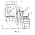
- FIG. 1 shows a cross-section through a perspective part of an arrangement shown for transmitting a rotational movement with a driven by an internal combustion engine rotor.
- a friction clutch 1 is provided with a rotationally driven rotor 2 for driving a shaft 3.
- the rotor 2 is here for example designed as a belt pulley with a belt support 4 for a multiple V-belt (not shown).
- the belt support 4 has an axial extent b to the axis S.
- a solenoid assembly 5 is housed in fail-safe design or with fail-safe.
- the electromagnet arrangement 5 shown schematically comprises a coil 6 which is at least partially surrounded by magnetic guiding means 7.
- the magnetic guiding means 7 comprise according to FIG. 1 a cross-sectionally T-shaped part 8 and a cross-sectionally L-shaped part 9.
- an anchor member 12 is attached via an armature spring 13 to a rotatably connected to the shaft 3 sleeve 14.
- the anchor member 12 is also made of a ferromagnetic material and is frictionally attracted by the magnetic action of the permanent magnets 10 to a friction portion 15 of the rotor 2 for a frictional connection between the anchor member 12 in the friction portion 15. In this state, the full revolution number of the rotor 2 is transmitted to the shaft 3 via the friction portion 15, the armature member 12, the armature spring 13 and the sleeve 14.
- the electromagnet assembly 5 is fixed e.g. attached to a housing section. This may be, for example, the water pump housing of a cooling water pump, if the friction clutch 1 via the shaft 3 for driving a water pump, the web portions 8a and 9a are spaced over a gap to adjacent webs 24 and 25 of the rotor 2.
- the rotor 2 is rotatably mounted on the shaft 3 via the radially inner web 25 via a ball bearing 16.
- Rotatably connected to the rotor is a ribbed wheel 17, the shaft 3 is rotated via an eddy current coupling 18 with a smaller than the drive speed of the rotor 2 in rotational movement when the armature element 12 is not rotatably connected to the rotor 2.
- a steel ring 22 is cast, whereby at 15 separated from the friction member 15 anchor member, the fin 17, which rotates at the rotor speed, via the eddy current coupling 18 a Towing speed on the shaft 3 transmits.
- the part 8 is T-shaped, so that the part of the 8th the permanent magnets 10 in the radial direction extend almost over the entire coil 6 and radially further outwards to below the belt support 4.
- a comparatively larger effective area of the permanent magnets 10 can be achieved, whereby a higher axial magnetic attraction force acts on the anchor member 12.
- the permanent magnets 10 are arranged in a direct arrangement in the direction of flow of the magnetic lines in the web portions 8a and 9a, whereby the magnetic flux emanating from the permanent magnet 10 is amplified.
- these are advantageously positioned so matched to the parts 8 and 9 and the coil 6 that when energizing the coil 6, for example via a cable 23 caused by the permanent magnets 10 attraction effect on the Anchor element 12 is compensated by a counter-acting coil magnetic field or safely repealed.
- the permanent magnets 10 are pulled radially outwardly of the coil 6, whereby by the larger annular surface of the Permanent magnets 10 a higher permanent magnetic attraction effect is achieved.
- the friction section 15 is provided with webs 24 and 25 directed axially towards the web sections 8a and 9a.
- the webs 24 and 25 are radially separated by a small air gap and axially overlapping to the web portions 8a and 9a.
Landscapes
- Engineering & Computer Science (AREA)
- General Engineering & Computer Science (AREA)
- Mechanical Engineering (AREA)
- Physics & Mathematics (AREA)
- Electromagnetism (AREA)
- Dynamo-Electric Clutches, Dynamo-Electric Brakes (AREA)
- Braking Arrangements (AREA)
Applications Claiming Priority (1)
| Application Number | Priority Date | Filing Date | Title |
|---|---|---|---|
| DE102008030165A DE102008030165A1 (de) | 2008-06-27 | 2008-06-27 | Reibschaltkupplung zur Drehmomentübertragung |
Publications (3)
| Publication Number | Publication Date |
|---|---|
| EP2138735A2 true EP2138735A2 (fr) | 2009-12-30 |
| EP2138735A3 EP2138735A3 (fr) | 2013-05-15 |
| EP2138735B1 EP2138735B1 (fr) | 2014-08-27 |
Family
ID=41119845
Family Applications (1)
| Application Number | Title | Priority Date | Filing Date |
|---|---|---|---|
| EP09007957.5A Not-in-force EP2138735B1 (fr) | 2008-06-27 | 2009-06-18 | Embrayage à friction destiné à la transmission de couple |
Country Status (4)
| Country | Link |
|---|---|
| US (1) | US8336696B2 (fr) |
| EP (1) | EP2138735B1 (fr) |
| BR (1) | BRPI0902031A2 (fr) |
| DE (1) | DE102008030165A1 (fr) |
Families Citing this family (8)
| Publication number | Priority date | Publication date | Assignee | Title |
|---|---|---|---|---|
| DE102009017566A1 (de) * | 2009-04-17 | 2010-10-21 | Licos Trucktec Gmbh | Flip-Flop-Kupplung |
| JP5229182B2 (ja) * | 2009-10-12 | 2013-07-03 | 株式会社デンソー | クラッチ機構 |
| US8732947B2 (en) * | 2010-02-25 | 2014-05-27 | Kit Masters Inc. | Method for accessing components of a fan clutch system |
| KR101803732B1 (ko) * | 2011-09-07 | 2017-12-01 | 한온시스템 주식회사 | 전자클러치 |
| DE102015121211A1 (de) * | 2015-12-07 | 2017-06-08 | Licos Trucktec Gmbh | Reibschaltkupplung für eine Drehmomentübertragung von einem um eine Achse antreibbaren Rotor auf eine anzutreibende Welle |
| EP3865725B1 (fr) * | 2020-02-17 | 2024-03-27 | Ratier-Figeac SAS | Limiteur |
| WO2025099579A1 (fr) * | 2023-11-10 | 2025-05-15 | Baruffaldi S.P.A. | Dispositif de commande pour pompe de recirculation à palier multiniveau fixé au corps de pompe |
| WO2025099582A1 (fr) * | 2023-11-10 | 2025-05-15 | Baruffaldi S.P.A. | Dispositif de commande pour faire fonctionner une pompe de recirculation avec palier multiniveau fixé à un rotor |
Family Cites Families (10)
| Publication number | Priority date | Publication date | Assignee | Title |
|---|---|---|---|---|
| DE7105355U (de) * | 1971-07-29 | Siemens Ag | Permanentmagnetbremse | |
| US2738449A (en) * | 1951-12-12 | 1956-03-13 | Warner Electric Brake & Clutch | Electromagnet construction |
| US2956658A (en) * | 1958-02-19 | 1960-10-18 | Eaton Mfg Co | Magnetic couplings |
| US3263784A (en) * | 1964-03-30 | 1966-08-02 | Pitts Ind Inc | Magnetic clutch |
| FR1455152A (fr) * | 1965-06-14 | 1966-10-14 | Warner Electric Brake & Clutch | Perfectionnements aux accouplements électromagnétiques à friction |
| AU459523B2 (en) * | 1972-08-07 | 1975-03-27 | Gkn Transmissions Limited | Improvements relating to clutches |
| US3842378A (en) * | 1973-07-20 | 1974-10-15 | Pitts Ind Inc | Double clutch for vehicle air conditioning compressor |
| US3899061A (en) * | 1974-04-29 | 1975-08-12 | Warner Electric Brake & Clutch | Excitation control for normally engaged, electrically released magnetic coupling |
| US4496922A (en) * | 1983-12-05 | 1985-01-29 | Warner Electric Brake & Clutch Company | Electromagnetically released coupling |
| JP2004190853A (ja) * | 2002-11-28 | 2004-07-08 | Usui Kokusai Sangyo Kaisha Ltd | マグネット式クラッチ装置 |
-
2008
- 2008-06-27 DE DE102008030165A patent/DE102008030165A1/de not_active Withdrawn
-
2009
- 2009-06-18 EP EP09007957.5A patent/EP2138735B1/fr not_active Not-in-force
- 2009-06-19 US US12/487,772 patent/US8336696B2/en not_active Expired - Fee Related
- 2009-06-29 BR BRPI0902031-4A patent/BRPI0902031A2/pt not_active IP Right Cessation
Non-Patent Citations (1)
| Title |
|---|
| None |
Also Published As
| Publication number | Publication date |
|---|---|
| DE102008030165A1 (de) | 2009-12-31 |
| EP2138735A3 (fr) | 2013-05-15 |
| US8336696B2 (en) | 2012-12-25 |
| US20090321213A1 (en) | 2009-12-31 |
| BRPI0902031A2 (pt) | 2010-05-11 |
| EP2138735B1 (fr) | 2014-08-27 |
Similar Documents
| Publication | Publication Date | Title |
|---|---|---|
| EP2138735B1 (fr) | Embrayage à friction destiné à la transmission de couple | |
| DE4430995B4 (de) | Elektromagnetische Kupplung | |
| DE102010047945B4 (de) | Kupplungsmechanismus und Kupplungssystem mit diesem | |
| DE69211088T2 (de) | Elektromagnetische Kupplung mit Dauermagnetbremse | |
| EP1248007B1 (fr) | Accouplement à fluide visqueux | |
| EP2275701B1 (fr) | Embrayage à friction électromagnétique | |
| EP2056432B1 (fr) | Embrayage magnétique | |
| DE102009024868A1 (de) | Elektromagnetische Kupplung | |
| DE69202229T2 (de) | Schalteinrichtung in einer Einwegkupplung des Reibungstyps. | |
| EP2105624A1 (fr) | Embrayage pouvant être actionné de manière électromagnétique et pompe à eau dotée d'un embrayage pouvant être actionné de manière électromagnétique | |
| DE69920320T2 (de) | Magnetische Brems- und Kupplungseinheit | |
| DE102004014865A1 (de) | Elektrischer Nockenwellerversteller mit Scheibenläufermotor | |
| DE3443523A1 (de) | Zweistufenkupplung, insbesondere fuer den antrieb eines kuehlluefters | |
| EP1256738A2 (fr) | Accouplement visqueux | |
| EP2262989B1 (fr) | Embrayage à friction et système d entraînement pour le refroidissement d un moteur à combustion d un véhicule équipé d un embrayage à friction | |
| DE202011051969U1 (de) | Wirbelstromkupplung | |
| EP2668393B1 (fr) | Dispositif de démarrage avec protection de surcharge | |
| EP2822150B1 (fr) | Machine électrique dotée d'un couplage intégré | |
| DE1913356A1 (de) | Elektromagnetisch betaetigter Kupplungs-Bremsmotor mit hohem Traegheitsmoment | |
| AT8304U1 (de) | Magnetorheologische kupplung mit lamellenbändern | |
| EP2275700B1 (fr) | Embrayage à friction électromagnétique | |
| DE102008049618A1 (de) | Antriebseinheit und elektromagnetisch betätigbare Reibscheibenkupplung | |
| DE10303183A1 (de) | Wirbelstromkupplung sowie Lüfterkupplung mit einer Wirbelstromkupplung | |
| DE19832253A1 (de) | Elektromotor und Verwendung eines Elektromotors | |
| WO2013023829A2 (fr) | Machine électrique et procédé de montage d'une machine électrique |
Legal Events
| Date | Code | Title | Description |
|---|---|---|---|
| PUAI | Public reference made under article 153(3) epc to a published international application that has entered the european phase |
Free format text: ORIGINAL CODE: 0009012 |
|
| AK | Designated contracting states |
Kind code of ref document: A2 Designated state(s): AT BE BG CH CY CZ DE DK EE ES FI FR GB GR HR HU IE IS IT LI LT LU LV MC MK MT NL NO PL PT RO SE SI SK TR |
|
| PUAL | Search report despatched |
Free format text: ORIGINAL CODE: 0009013 |
|
| AK | Designated contracting states |
Kind code of ref document: A3 Designated state(s): AT BE BG CH CY CZ DE DK EE ES FI FR GB GR HR HU IE IS IT LI LT LU LV MC MK MT NL NO PL PT RO SE SI SK TR |
|
| AX | Request for extension of the european patent |
Extension state: AL BA RS |
|
| RIC1 | Information provided on ipc code assigned before grant |
Ipc: F16D 27/14 20060101ALI20130410BHEP Ipc: F16D 27/112 20060101AFI20130410BHEP |
|
| 17P | Request for examination filed |
Effective date: 20131115 |
|
| RBV | Designated contracting states (corrected) |
Designated state(s): AT BE BG CH CY CZ DE DK EE ES FI FR GB GR HR HU IE IS IT LI LT LU LV MC MK MT NL NO PL PT RO SE SI SK TR |
|
| GRAP | Despatch of communication of intention to grant a patent |
Free format text: ORIGINAL CODE: EPIDOSNIGR1 |
|
| INTG | Intention to grant announced |
Effective date: 20140416 |
|
| GRAS | Grant fee paid |
Free format text: ORIGINAL CODE: EPIDOSNIGR3 |
|
| GRAA | (expected) grant |
Free format text: ORIGINAL CODE: 0009210 |
|
| AK | Designated contracting states |
Kind code of ref document: B1 Designated state(s): AT BE BG CH CY CZ DE DK EE ES FI FR GB GR HR HU IE IS IT LI LT LU LV MC MK MT NL NO PL PT RO SE SI SK TR |
|
| REG | Reference to a national code |
Ref country code: GB Ref legal event code: FG4D Free format text: NOT ENGLISH |
|
| REG | Reference to a national code |
Ref country code: CH Ref legal event code: EP |
|
| REG | Reference to a national code |
Ref country code: AT Ref legal event code: REF Ref document number: 684672 Country of ref document: AT Kind code of ref document: T Effective date: 20140915 |
|
| REG | Reference to a national code |
Ref country code: IE Ref legal event code: FG4D Free format text: LANGUAGE OF EP DOCUMENT: GERMAN |
|
| REG | Reference to a national code |
Ref country code: DE Ref legal event code: R096 Ref document number: 502009009847 Country of ref document: DE Effective date: 20141009 |
|
| REG | Reference to a national code |
Ref country code: LT Ref legal event code: MG4D |
|
| REG | Reference to a national code |
Ref country code: NL Ref legal event code: VDEP Effective date: 20140827 |
|
| PG25 | Lapsed in a contracting state [announced via postgrant information from national office to epo] |
Ref country code: SE Free format text: LAPSE BECAUSE OF FAILURE TO SUBMIT A TRANSLATION OF THE DESCRIPTION OR TO PAY THE FEE WITHIN THE PRESCRIBED TIME-LIMIT Effective date: 20140827 Ref country code: NO Free format text: LAPSE BECAUSE OF FAILURE TO SUBMIT A TRANSLATION OF THE DESCRIPTION OR TO PAY THE FEE WITHIN THE PRESCRIBED TIME-LIMIT Effective date: 20141127 Ref country code: LT Free format text: LAPSE BECAUSE OF FAILURE TO SUBMIT A TRANSLATION OF THE DESCRIPTION OR TO PAY THE FEE WITHIN THE PRESCRIBED TIME-LIMIT Effective date: 20140827 Ref country code: FI Free format text: LAPSE BECAUSE OF FAILURE TO SUBMIT A TRANSLATION OF THE DESCRIPTION OR TO PAY THE FEE WITHIN THE PRESCRIBED TIME-LIMIT Effective date: 20140827 Ref country code: GR Free format text: LAPSE BECAUSE OF FAILURE TO SUBMIT A TRANSLATION OF THE DESCRIPTION OR TO PAY THE FEE WITHIN THE PRESCRIBED TIME-LIMIT Effective date: 20141128 Ref country code: PT Free format text: LAPSE BECAUSE OF FAILURE TO SUBMIT A TRANSLATION OF THE DESCRIPTION OR TO PAY THE FEE WITHIN THE PRESCRIBED TIME-LIMIT Effective date: 20141229 Ref country code: BG Free format text: LAPSE BECAUSE OF FAILURE TO SUBMIT A TRANSLATION OF THE DESCRIPTION OR TO PAY THE FEE WITHIN THE PRESCRIBED TIME-LIMIT Effective date: 20141127 Ref country code: ES Free format text: LAPSE BECAUSE OF FAILURE TO SUBMIT A TRANSLATION OF THE DESCRIPTION OR TO PAY THE FEE WITHIN THE PRESCRIBED TIME-LIMIT Effective date: 20140827 |
|
| PG25 | Lapsed in a contracting state [announced via postgrant information from national office to epo] |
Ref country code: LV Free format text: LAPSE BECAUSE OF FAILURE TO SUBMIT A TRANSLATION OF THE DESCRIPTION OR TO PAY THE FEE WITHIN THE PRESCRIBED TIME-LIMIT Effective date: 20140827 Ref country code: CY Free format text: LAPSE BECAUSE OF FAILURE TO SUBMIT A TRANSLATION OF THE DESCRIPTION OR TO PAY THE FEE WITHIN THE PRESCRIBED TIME-LIMIT Effective date: 20140827 Ref country code: HR Free format text: LAPSE BECAUSE OF FAILURE TO SUBMIT A TRANSLATION OF THE DESCRIPTION OR TO PAY THE FEE WITHIN THE PRESCRIBED TIME-LIMIT Effective date: 20140827 Ref country code: IS Free format text: LAPSE BECAUSE OF FAILURE TO SUBMIT A TRANSLATION OF THE DESCRIPTION OR TO PAY THE FEE WITHIN THE PRESCRIBED TIME-LIMIT Effective date: 20141227 |
|
| PG25 | Lapsed in a contracting state [announced via postgrant information from national office to epo] |
Ref country code: NL Free format text: LAPSE BECAUSE OF FAILURE TO SUBMIT A TRANSLATION OF THE DESCRIPTION OR TO PAY THE FEE WITHIN THE PRESCRIBED TIME-LIMIT Effective date: 20140827 |
|
| PG25 | Lapsed in a contracting state [announced via postgrant information from national office to epo] |
Ref country code: RO Free format text: LAPSE BECAUSE OF FAILURE TO SUBMIT A TRANSLATION OF THE DESCRIPTION OR TO PAY THE FEE WITHIN THE PRESCRIBED TIME-LIMIT Effective date: 20140827 Ref country code: EE Free format text: LAPSE BECAUSE OF FAILURE TO SUBMIT A TRANSLATION OF THE DESCRIPTION OR TO PAY THE FEE WITHIN THE PRESCRIBED TIME-LIMIT Effective date: 20140827 Ref country code: SK Free format text: LAPSE BECAUSE OF FAILURE TO SUBMIT A TRANSLATION OF THE DESCRIPTION OR TO PAY THE FEE WITHIN THE PRESCRIBED TIME-LIMIT Effective date: 20140827 Ref country code: CZ Free format text: LAPSE BECAUSE OF FAILURE TO SUBMIT A TRANSLATION OF THE DESCRIPTION OR TO PAY THE FEE WITHIN THE PRESCRIBED TIME-LIMIT Effective date: 20140827 Ref country code: IT Free format text: LAPSE BECAUSE OF FAILURE TO SUBMIT A TRANSLATION OF THE DESCRIPTION OR TO PAY THE FEE WITHIN THE PRESCRIBED TIME-LIMIT Effective date: 20140827 Ref country code: DK Free format text: LAPSE BECAUSE OF FAILURE TO SUBMIT A TRANSLATION OF THE DESCRIPTION OR TO PAY THE FEE WITHIN THE PRESCRIBED TIME-LIMIT Effective date: 20140827 |
|
| REG | Reference to a national code |
Ref country code: DE Ref legal event code: R097 Ref document number: 502009009847 Country of ref document: DE |
|
| PG25 | Lapsed in a contracting state [announced via postgrant information from national office to epo] |
Ref country code: PL Free format text: LAPSE BECAUSE OF FAILURE TO SUBMIT A TRANSLATION OF THE DESCRIPTION OR TO PAY THE FEE WITHIN THE PRESCRIBED TIME-LIMIT Effective date: 20140827 |
|
| PLBE | No opposition filed within time limit |
Free format text: ORIGINAL CODE: 0009261 |
|
| STAA | Information on the status of an ep patent application or granted ep patent |
Free format text: STATUS: NO OPPOSITION FILED WITHIN TIME LIMIT |
|
| 26N | No opposition filed |
Effective date: 20150528 |
|
| PG25 | Lapsed in a contracting state [announced via postgrant information from national office to epo] |
Ref country code: SI Free format text: LAPSE BECAUSE OF FAILURE TO SUBMIT A TRANSLATION OF THE DESCRIPTION OR TO PAY THE FEE WITHIN THE PRESCRIBED TIME-LIMIT Effective date: 20140827 |
|
| PG25 | Lapsed in a contracting state [announced via postgrant information from national office to epo] |
Ref country code: MC Free format text: LAPSE BECAUSE OF FAILURE TO SUBMIT A TRANSLATION OF THE DESCRIPTION OR TO PAY THE FEE WITHIN THE PRESCRIBED TIME-LIMIT Effective date: 20140827 |
|
| REG | Reference to a national code |
Ref country code: CH Ref legal event code: PL |
|
| GBPC | Gb: european patent ceased through non-payment of renewal fee |
Effective date: 20150618 |
|
| PG25 | Lapsed in a contracting state [announced via postgrant information from national office to epo] |
Ref country code: LU Free format text: LAPSE BECAUSE OF FAILURE TO SUBMIT A TRANSLATION OF THE DESCRIPTION OR TO PAY THE FEE WITHIN THE PRESCRIBED TIME-LIMIT Effective date: 20150618 |
|
| REG | Reference to a national code |
Ref country code: IE Ref legal event code: MM4A |
|
| REG | Reference to a national code |
Ref country code: FR Ref legal event code: ST Effective date: 20160229 |
|
| PG25 | Lapsed in a contracting state [announced via postgrant information from national office to epo] |
Ref country code: CH Free format text: LAPSE BECAUSE OF NON-PAYMENT OF DUE FEES Effective date: 20150630 Ref country code: LI Free format text: LAPSE BECAUSE OF NON-PAYMENT OF DUE FEES Effective date: 20150630 Ref country code: GB Free format text: LAPSE BECAUSE OF NON-PAYMENT OF DUE FEES Effective date: 20150618 Ref country code: IE Free format text: LAPSE BECAUSE OF NON-PAYMENT OF DUE FEES Effective date: 20150618 |
|
| PG25 | Lapsed in a contracting state [announced via postgrant information from national office to epo] |
Ref country code: FR Free format text: LAPSE BECAUSE OF NON-PAYMENT OF DUE FEES Effective date: 20150630 |
|
| REG | Reference to a national code |
Ref country code: AT Ref legal event code: MM01 Ref document number: 684672 Country of ref document: AT Kind code of ref document: T Effective date: 20150618 |
|
| PG25 | Lapsed in a contracting state [announced via postgrant information from national office to epo] |
Ref country code: AT Free format text: LAPSE BECAUSE OF NON-PAYMENT OF DUE FEES Effective date: 20150618 |
|
| PG25 | Lapsed in a contracting state [announced via postgrant information from national office to epo] |
Ref country code: MT Free format text: LAPSE BECAUSE OF FAILURE TO SUBMIT A TRANSLATION OF THE DESCRIPTION OR TO PAY THE FEE WITHIN THE PRESCRIBED TIME-LIMIT Effective date: 20140827 |
|
| PG25 | Lapsed in a contracting state [announced via postgrant information from national office to epo] |
Ref country code: HU Free format text: LAPSE BECAUSE OF FAILURE TO SUBMIT A TRANSLATION OF THE DESCRIPTION OR TO PAY THE FEE WITHIN THE PRESCRIBED TIME-LIMIT; INVALID AB INITIO Effective date: 20090618 |
|
| PG25 | Lapsed in a contracting state [announced via postgrant information from national office to epo] |
Ref country code: BE Free format text: LAPSE BECAUSE OF NON-PAYMENT OF DUE FEES Effective date: 20150630 |
|
| PG25 | Lapsed in a contracting state [announced via postgrant information from national office to epo] |
Ref country code: TR Free format text: LAPSE BECAUSE OF FAILURE TO SUBMIT A TRANSLATION OF THE DESCRIPTION OR TO PAY THE FEE WITHIN THE PRESCRIBED TIME-LIMIT Effective date: 20140827 |
|
| PG25 | Lapsed in a contracting state [announced via postgrant information from national office to epo] |
Ref country code: MK Free format text: LAPSE BECAUSE OF FAILURE TO SUBMIT A TRANSLATION OF THE DESCRIPTION OR TO PAY THE FEE WITHIN THE PRESCRIBED TIME-LIMIT Effective date: 20140827 |
|
| PGFP | Annual fee paid to national office [announced via postgrant information from national office to epo] |
Ref country code: DE Payment date: 20210727 Year of fee payment: 13 |
|
| REG | Reference to a national code |
Ref country code: DE Ref legal event code: R119 Ref document number: 502009009847 Country of ref document: DE |
|
| PG25 | Lapsed in a contracting state [announced via postgrant information from national office to epo] |
Ref country code: DE Free format text: LAPSE BECAUSE OF NON-PAYMENT OF DUE FEES Effective date: 20230103 |