EP2139074A2 - Dispositif de raccordement pour câble multipolaire - Google Patents
Dispositif de raccordement pour câble multipolaire Download PDFInfo
- Publication number
- EP2139074A2 EP2139074A2 EP09163706A EP09163706A EP2139074A2 EP 2139074 A2 EP2139074 A2 EP 2139074A2 EP 09163706 A EP09163706 A EP 09163706A EP 09163706 A EP09163706 A EP 09163706A EP 2139074 A2 EP2139074 A2 EP 2139074A2
- Authority
- EP
- European Patent Office
- Prior art keywords
- flat cable
- connecting device
- separating
- conductors
- contacts
- Prior art date
- Legal status (The legal status is an assumption and is not a legal conclusion. Google has not performed a legal analysis and makes no representation as to the accuracy of the status listed.)
- Withdrawn
Links
- 239000004020 conductor Substances 0.000 title claims abstract description 51
- 238000009413 insulation Methods 0.000 claims abstract description 12
- 238000005520 cutting process Methods 0.000 claims description 6
- 238000006073 displacement reaction Methods 0.000 claims description 2
- 230000001681 protective effect Effects 0.000 claims description 2
- 238000002955 isolation Methods 0.000 claims 1
- 230000000149 penetrating effect Effects 0.000 abstract 1
- 238000005304 joining Methods 0.000 description 2
- 238000000926 separation method Methods 0.000 description 2
- 238000013459 approach Methods 0.000 description 1
- 230000000712 assembly Effects 0.000 description 1
- 238000000429 assembly Methods 0.000 description 1
- 238000010276 construction Methods 0.000 description 1
- 230000001419 dependent effect Effects 0.000 description 1
- 238000009434 installation Methods 0.000 description 1
- 238000000034 method Methods 0.000 description 1
- 238000002360 preparation method Methods 0.000 description 1
- 238000004080 punching Methods 0.000 description 1
Images


Classifications
-
- H—ELECTRICITY
- H01—ELECTRIC ELEMENTS
- H01R—ELECTRICALLY-CONDUCTIVE CONNECTIONS; STRUCTURAL ASSOCIATIONS OF A PLURALITY OF MUTUALLY-INSULATED ELECTRICAL CONNECTING ELEMENTS; COUPLING DEVICES; CURRENT COLLECTORS
- H01R12/00—Structural associations of a plurality of mutually-insulated electrical connecting elements, specially adapted for printed circuits, e.g. printed circuit boards [PCB], flat or ribbon cables, or like generally planar structures, e.g. terminal strips, terminal blocks; Coupling devices specially adapted for printed circuits, flat or ribbon cables, or like generally planar structures; Terminals specially adapted for contact with, or insertion into, printed circuits, flat or ribbon cables, or like generally planar structures
- H01R12/50—Fixed connections
- H01R12/59—Fixed connections for flexible printed circuits, flat or ribbon cables or like structures
- H01R12/65—Fixed connections for flexible printed circuits, flat or ribbon cables or like structures characterised by the terminal
- H01R12/67—Fixed connections for flexible printed circuits, flat or ribbon cables or like structures characterised by the terminal insulation penetrating terminals
- H01R12/675—Fixed connections for flexible printed circuits, flat or ribbon cables or like structures characterised by the terminal insulation penetrating terminals with contacts having at least a slotted plate for penetration of cable insulation, e.g. insulation displacement contacts for round conductor flat cables
-
- H—ELECTRICITY
- H01—ELECTRIC ELEMENTS
- H01R—ELECTRICALLY-CONDUCTIVE CONNECTIONS; STRUCTURAL ASSOCIATIONS OF A PLURALITY OF MUTUALLY-INSULATED ELECTRICAL CONNECTING ELEMENTS; COUPLING DEVICES; CURRENT COLLECTORS
- H01R4/00—Electrically-conductive connections between two or more conductive members in direct contact, i.e. touching one another; Means for effecting or maintaining such contact; Electrically-conductive connections having two or more spaced connecting locations for conductors and using contact members penetrating insulation
- H01R4/24—Connections using contact members penetrating or cutting insulation or cable strands
- H01R4/2404—Connections using contact members penetrating or cutting insulation or cable strands the contact members having teeth, prongs, pins or needles penetrating the insulation
- H01R4/2412—Connections using contact members penetrating or cutting insulation or cable strands the contact members having teeth, prongs, pins or needles penetrating the insulation actuated by insulated cams or wedges
-
- H—ELECTRICITY
- H01—ELECTRIC ELEMENTS
- H01R—ELECTRICALLY-CONDUCTIVE CONNECTIONS; STRUCTURAL ASSOCIATIONS OF A PLURALITY OF MUTUALLY-INSULATED ELECTRICAL CONNECTING ELEMENTS; COUPLING DEVICES; CURRENT COLLECTORS
- H01R12/00—Structural associations of a plurality of mutually-insulated electrical connecting elements, specially adapted for printed circuits, e.g. printed circuit boards [PCB], flat or ribbon cables, or like generally planar structures, e.g. terminal strips, terminal blocks; Coupling devices specially adapted for printed circuits, flat or ribbon cables, or like generally planar structures; Terminals specially adapted for contact with, or insertion into, printed circuits, flat or ribbon cables, or like generally planar structures
- H01R12/50—Fixed connections
- H01R12/59—Fixed connections for flexible printed circuits, flat or ribbon cables or like structures
- H01R12/61—Fixed connections for flexible printed circuits, flat or ribbon cables or like structures connecting to flexible printed circuits, flat or ribbon cables or like structures
- H01R12/613—Fixed connections for flexible printed circuits, flat or ribbon cables or like structures connecting to flexible printed circuits, flat or ribbon cables or like structures by means of interconnecting elements
- H01R12/616—Fixed connections for flexible printed circuits, flat or ribbon cables or like structures connecting to flexible printed circuits, flat or ribbon cables or like structures by means of interconnecting elements having contacts penetrating insulation for making contact with conductors, e.g. needle points
Definitions
- the invention relates to a connecting device for contacting conductors of a continuous cable, in particular a continuous flat cable, which is suitable for installation in a lift shaft, according to the preamble of claim 1.
- Connecting devices for the ends of flat cables reveal the US 5,429,526 or the DE 44 36 829 A1 .
- Other connecting devices - even with insulation piercing contacts - are so from the DE 34 22 607 C2 and the DE 44 02 837 A1 known.
- the invention therefore has the task of further optimizing this generic construction.
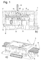
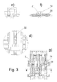
- Fig. 1 shows various views of a connection device 1, which is designed for contacting a flat cable 2, which has a plurality of mutually parallel conductors 3, which may each be surrounded by insulation and embedded in a higher cable sheath 4.
- the flat cable 2 may be routed for example in a lift shaft.
- the connecting device has a multi-part housing 5, which has at least one base section 6 and a cover section 7, which in turn may each be formed in each case in several parts.
- a multi-part housing 5 which has at least one base section 6 and a cover section 7, which in turn may each be formed in each case in several parts.
- the base portion 6 preferably has a plurality of insulation piercing contacts 8 (see Fig. 1a ), which contact individual or all of the conductors 3 of the flat cable 2 when the base section 6 is joined to the cover section 7.
- at least one of the conductors 3 is contacted at two locations spaced apart axially from one another in the main extension direction of the conductor 3, wherein this conductor 3 is to be cut between the contact points to which it is contacted with the contacts 8, as between the contacted ends, for example, an electronics or Like.
- To switch for example, to realize a safety circuit for an elevator.
- the joining of the base portion 6 with the lid portion 7 can - as in the US 7,347,716 B2 described - done with the help of wedge assemblies between these units or in other ways, so with the aid of screws (not shown), with which the cover portion 7 and the base portion 6 are moved toward each other, wherein the insulation piercing contacts 8 to be contacted Contact conductor 3.
- separating element Only in this position is at least one separating element, here a separating pin 9, which may have a cutting edge 10, in the direction shown by the arrow X direction in a corresponding opening 11 - here in the lid portion 7 and / or in the base portion 6 - inserted, which extends to the ribbon cable 2.
- a separating pin 9 which may have a cutting edge 10, in the direction shown by the arrow X direction in a corresponding opening 11 - here in the lid portion 7 and / or in the base portion 6 - inserted, which extends to the ribbon cable 2.
- At least one or more separating pin (s) 9 in each case at least one of the conductors 3 can be severed in a region between the contact points in which this conductor is contacted by the contact elements 8 in order to produce an interruption of this conductor 3.
- a plurality of the separating pins 8 and the openings 11 it is also possible for a plurality of the separating pins 8 and the openings 11 to be provided.
- the separating pins 8 may also be formed as a corresponding pin-like projections on a tool pliers, which is used for severing the conductor 3, and which serves after contacting the conductor 3 for severing the conductor at the designated locations by the release pins on the Pliers are inserted into the openings 11.
- An advantage of this invention is that the contacting of the flat cable and thus the joining of the cover section 7 and the base section 6 is completely completed even before the conductors are severed, ensuring in a simple manner that the conductors 3 to be cut are always in the correct position Place to be severed.
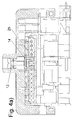
- connection device shown in these figures is different than the embodiment of Fig. 1 designed such that forcibly first with a separator a severing of the flat cable 2 must be made at the at least one or more designated points before the actual wiring of the flat cable using the IDC contacts 8 can take place.
- a particular advantage of this solution is that the contacting of the conductors 3 is not possible if the conductors 3 have not yet been cut through and that nevertheless by the selected Embodiment contacting also the respective severed conductor 3 is carried out after severing the flat cable 2 for the safety circuit on both sides of the separation point.
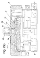
- Fig. 2 to 5 To Fig. 2 to 5 is the lid portion 7 on the base portion 6, which is provided with a pressure plate 25, slidably guided.
- the flat cable 2 is set between the lid portion 7 and the pressure plate 25 on the base portion 6.
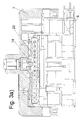
- a slider 12 is arranged for severing at least one conductor or a plurality of conductors of the flat cable, wherein the movable in the main extension direction of the cable 2 and perpendicular to the flat cable movable slide 12 has a screw 13 with its end on at least one separating element 14th acts, which in turn is arranged above the flat cable 2, so that by means of screwing the screw 13, the separating element 14 is pressed axially with pin-like projections 26 in the flat cable 2, in turn with a cutting area 17 to sever one or more conductors 3.
- the separating element 14 may be formed according to a particularly preferred embodiment as a U-shaped or comb-like element with two or more of the pin-like projections 26.
- the screw 13 is preferably in a slot 15 e.g. slidably guided in the pressure plate 25 in the main direction of the flat cable 2.
- the separating pin 14 further penetrates a nut 16, which is displaceable on the one hand in the main extension direction of the flat cable 2 and the other hand perpendicular to Flat cable in the lid portion 7 is immovable, so that it forms an abutment on which the screw 13 is supported.
- the U-shaped, bow-like separating element 14 has at its end remote from the screw head or at the free ends of the pin-like projections 26 at least one or more knives 17 for severing the at least one conductor 3.
- the pin-like projections 26 are further formed in each case in the axially adjoining the blade 17 region 18 isolated.
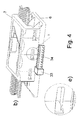
- the separating element 14 is designed as a U-shaped bracket, wherein a central franking 28 in the separating element has the shape of a T.
- a central franking 28 in the separating element has the shape of a T.
- the franking 28 is wide enough to be guided over a broadening or a stop 19 in the pressure plate 25, whereas the franking 28 is too narrow in its narrow region 30 for this purpose.
- it is therefore necessary to first pierce them with the separating element 14 perpendicular to the main extension direction of the conductor 3, and then to move the lid portion 7 in the contacting position can.
- Step 1 through Step 4 the screwing (and thus interrupting) of the flat cable 2, inter alia, by means of a screwdriver 27 (see Fig. 5 ) in four steps, labeled Step 1 through Step 4.
- Step1 The lid portion 7 together with the pressure plate 25 and the slide 12 are placed on the base portion 6 ( Fig. 2 ).
- Step2 The bow-like separating element 14 guided on a rail-like web 32 into the slot 15 of the pressure plate 25 runs against the stop 19 on the web 32, which is formed on the pressure plate 25, for example, so that the lid section 7 is blocked in this position and not further in Ladder direction can be moved ( Fig. 3 ).
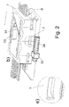
- Step 3 The flat cable 2 is punched out by screwing the screw 13 with the separating element 14.
- the cutting element releases the slide 12 and the cover gate 7 on the pressure plate 27 again for movement in the conductor direction ( Fig. 4 ).
- Step 4 Then, the flat cable 2 is contacted with the insulation piercing contacts 8, for example by means of a screwdriver, which shifts the lid portion (7) at the base portion (6) so that the wedge assembly comes into action and presses the flat cable into the IDC contacts.
- the safety circuit is feasible ( Fig. 5 ).
- Corresponding guide means are provided in the cover section and in the base section, which permit a displacement and contacting of the relatively movable housing sections in the manner of the state of the prior art discussed.
- a particular advantage of this solution is that the punching of the flat cable 2 can not be forgotten.
- a connecting device 34 designed here as a socket is further formed, which is conductively connected to the contacts 8 for contacting the cable, here the flat cable, and which serves to external conductors outside the housing 5 with a plug (not shown) conductive to the contacts 8 to connect, for example, to realize a T-shaped connection to the flat cable.
- a protective device 33 is further formed on another relative to the first movable portion of the housing 5, in particular on the lid portion 7, which is designed here as a collar which moves with the lid portion 7 to contact the connecting device 34, here with a plug, to prevent as long as the Bescharisvorgang the flat cable with the contacts 8 and preferably also the cutting is not completed, ie here, until the Cover section 7 from the position of Fig. 2 in the contact position of Fig. 5 was moved.
- the collar 33 moves with the lid portion 7 from a position in which it partially covers the connecting device and thus prevents plugging into the connecting device 34 (FIG. Fig. 2 to Fig. 4 ) to a position laterally of the socket in which a plug can be inserted into said socket ( Fig. 5 ).
- This protection device ensures that the connection device can not be contacted until the wiring process of the flat cable has been completely completed. It could also be provided in other ways relatively movable housing sections, so at relatively rotatable sections. The same applies to the other features in this description.
Landscapes
- Multi-Conductor Connections (AREA)
- Coupling Device And Connection With Printed Circuit (AREA)
Applications Claiming Priority (1)
| Application Number | Priority Date | Filing Date | Title |
|---|---|---|---|
| DE202008008696U DE202008008696U1 (de) | 2008-06-28 | 2008-06-28 | Anschlussvorrichtung für Mehrleiterkabel |
Publications (2)
| Publication Number | Publication Date |
|---|---|
| EP2139074A2 true EP2139074A2 (fr) | 2009-12-30 |
| EP2139074A3 EP2139074A3 (fr) | 2014-03-26 |
Family
ID=41110772
Family Applications (1)
| Application Number | Title | Priority Date | Filing Date |
|---|---|---|---|
| EP09163706.6A Withdrawn EP2139074A3 (fr) | 2008-06-28 | 2009-06-25 | Dispositif de raccordement pour câble multipolaire |
Country Status (2)
| Country | Link |
|---|---|
| EP (1) | EP2139074A3 (fr) |
| DE (1) | DE202008008696U1 (fr) |
Families Citing this family (1)
| Publication number | Priority date | Publication date | Assignee | Title |
|---|---|---|---|---|
| DE102023205461A1 (de) | 2023-06-13 | 2024-12-19 | BSH Hausgeräte GmbH | Verbinder-Vorrichtung für einen Kabelbaum |
Citations (6)
| Publication number | Priority date | Publication date | Assignee | Title |
|---|---|---|---|---|
| DE2535933A1 (de) | 1974-08-15 | 1976-02-26 | Aumann Vital L | Elektrisches anschluss-system und verfahren zu dessen erstellung und pruefung |
| DE3422607C2 (fr) | 1983-06-18 | 1993-02-25 | ||
| US5429526A (en) | 1993-04-28 | 1995-07-04 | Ann; Young S. | Wire connector |
| DE4402837A1 (de) | 1994-01-31 | 1995-08-03 | Daetwyler Ag | Flachkabel |
| DE4436829A1 (de) | 1994-10-14 | 1996-04-18 | Siemens Ag | Kontaktierungseinrichtung |
| EP1855356A1 (fr) | 2006-05-11 | 2007-11-14 | Weidmüller Interface GmbH & Co. KG | Appareil de connexion pour câbles multiconducteur |
Family Cites Families (8)
| Publication number | Priority date | Publication date | Assignee | Title |
|---|---|---|---|---|
| US4062615A (en) * | 1976-12-06 | 1977-12-13 | Thomas & Betts Corporation | Electrical contact |
| DE3711675A1 (de) * | 1987-04-07 | 1988-10-27 | Krone Ag | Aderverbinder fuer kabeladern, insbesondere von fernmeldekabeln |
| US5174782A (en) * | 1992-01-06 | 1992-12-29 | Molex Incorporated | Electrical cable clamping device with cable foil grounding means |
| JPH08162177A (ja) * | 1994-12-05 | 1996-06-21 | Yazaki Corp | 圧接コネクタへの電線圧接方法及び圧接コネクタ |
| JP3541540B2 (ja) * | 1996-02-05 | 2004-07-14 | 住友電装株式会社 | 圧接ジョイントコネクタを用いたワイヤハーネス |
| DE59906372D1 (de) * | 1999-10-15 | 2003-08-28 | Endress & Hauser Gmbh & Co Kg | Elektrische Sicherungsvorrichtung |
| JP3935036B2 (ja) * | 2002-09-27 | 2007-06-20 | 株式会社フジクラ | フラットハーネス |
| DE202006019520U1 (de) * | 2006-12-21 | 2008-04-30 | Weidmüller Interface GmbH & Co. KG | Anschlussvorrichtung für Mehrleiterkabel |
-
2008
- 2008-06-28 DE DE202008008696U patent/DE202008008696U1/de not_active Expired - Lifetime
-
2009
- 2009-06-25 EP EP09163706.6A patent/EP2139074A3/fr not_active Withdrawn
Patent Citations (7)
| Publication number | Priority date | Publication date | Assignee | Title |
|---|---|---|---|---|
| DE2535933A1 (de) | 1974-08-15 | 1976-02-26 | Aumann Vital L | Elektrisches anschluss-system und verfahren zu dessen erstellung und pruefung |
| DE3422607C2 (fr) | 1983-06-18 | 1993-02-25 | ||
| US5429526A (en) | 1993-04-28 | 1995-07-04 | Ann; Young S. | Wire connector |
| DE4402837A1 (de) | 1994-01-31 | 1995-08-03 | Daetwyler Ag | Flachkabel |
| DE4436829A1 (de) | 1994-10-14 | 1996-04-18 | Siemens Ag | Kontaktierungseinrichtung |
| EP1855356A1 (fr) | 2006-05-11 | 2007-11-14 | Weidmüller Interface GmbH & Co. KG | Appareil de connexion pour câbles multiconducteur |
| US7347716B2 (en) | 2006-05-11 | 2008-03-25 | Weidmüller Interface GmbH & Co. KG | Connector arrangement for multi-conductor cables |
Also Published As
| Publication number | Publication date |
|---|---|
| DE202008008696U1 (de) | 2009-11-19 |
| EP2139074A3 (fr) | 2014-03-26 |
Similar Documents
| Publication | Publication Date | Title |
|---|---|---|
| EP1855356B1 (fr) | Appareil de connexion pour câbles multiconducteur | |
| EP1936747B1 (fr) | Dispositif de raccordement pour câble multipolaire | |
| EP2019449B1 (fr) | Borne de connexion à vis et son procédé de fabrication | |
| DE19835459C2 (de) | Anschlußklemme für elektrische Leiter | |
| EP3021421B1 (fr) | Dispositif de raccordement pour cable multiconducteur | |
| EP1191633B1 (fr) | Barette à borne à déplacement d'isolation avec pièces pour contacter les fils avec les bornes | |
| EP1008205B1 (fr) | Borne serre-fils pour le raccordement sans denudage de conducteurs isoles | |
| EP1691449B1 (fr) | Dispositif de raccordement électrique d'au moins deux conducteurs principaux isolés d'un câble d'alimentation électrique, en particulier borne de dérivation | |
| EP1523065B1 (fr) | Borne électrique | |
| DE102011001152B4 (de) | Kontaktelement und Kontaktelementbaueinheit | |
| EP2139074A2 (fr) | Dispositif de raccordement pour câble multipolaire | |
| DE19937720C2 (de) | Verbindungsvorrichtung mit isolationsdurchdringendem Schlitz für einen elektrischen Draht | |
| EP3117487B1 (fr) | Dispositif de protection contre les surtensions comprenant au moins un appareil de protection contre les surtensions | |
| EP3151337B1 (fr) | Câble plat et procédé d'isolation de câbles plats | |
| DE102005005917B4 (de) | Anschlussklemme für einen isolierten elektrischen Leiter | |
| DE102009040646B3 (de) | Vorrichtung zum Abtrennen eines Brückensteges eines Steckbrückensystems | |
| EP3759766B1 (fr) | Dispositif de protection contre les surtensions, comprenant au moins un appareil de protection contre les surtensions, composé d'un socle et d'une pièce mâle pouvant être raccordée au socle | |
| EP1279206B1 (fr) | Dispositif perce-isolant | |
| EP1972032B1 (fr) | Contact autodénudant pour cordons | |
| EP1463151A2 (fr) | Dispositif de connexion ayant un contact perçant | |
| DE8908254U1 (de) | Klemmverbinder | |
| WO2025214545A1 (fr) | Outil d'assemblage pour connecteur enfichable et son procédé d'utilisation | |
| EP1503456B1 (fr) | Connecteur électrique plus particulièrement avec fiche ronde | |
| DE20214727U1 (de) | Anschlussklemme | |
| DE10243107B4 (de) | Reihenklemme und Führungshülse |
Legal Events
| Date | Code | Title | Description |
|---|---|---|---|
| PUAI | Public reference made under article 153(3) epc to a published international application that has entered the european phase |
Free format text: ORIGINAL CODE: 0009012 |
|
| AK | Designated contracting states |
Kind code of ref document: A2 Designated state(s): AT BE BG CH CY CZ DE DK EE ES FI FR GB GR HR HU IE IS IT LI LT LU LV MC MK MT NL NO PL PT RO SE SI SK TR |
|
| PUAL | Search report despatched |
Free format text: ORIGINAL CODE: 0009013 |
|
| AK | Designated contracting states |
Kind code of ref document: A3 Designated state(s): AT BE BG CH CY CZ DE DK EE ES FI FR GB GR HR HU IE IS IT LI LT LU LV MC MK MT NL NO PL PT RO SE SI SK TR |
|
| AX | Request for extension of the european patent |
Extension state: AL BA RS |
|
| RIC1 | Information provided on ipc code assigned before grant |
Ipc: H01R 12/67 20110101AFI20140218BHEP Ipc: H01R 4/24 20060101ALI20140218BHEP |
|
| 17P | Request for examination filed |
Effective date: 20140707 |
|
| RBV | Designated contracting states (corrected) |
Designated state(s): AT BE BG CH CY CZ DE DK EE ES FI FR GB GR HR HU IE IS IT LI LT LU LV MC MK MT NL NO PL PT RO SE SI SK TR |
|
| STAA | Information on the status of an ep patent application or granted ep patent |
Free format text: STATUS: THE APPLICATION IS DEEMED TO BE WITHDRAWN |
|
| 18D | Application deemed to be withdrawn |
Effective date: 20140927 |
|
| REG | Reference to a national code |
Ref country code: DE Ref legal event code: R079 Free format text: PREVIOUS MAIN CLASS: H01R0012080000 Ipc: H01R0012770000 |
|
| REG | Reference to a national code |
Ref country code: DE Ref legal event code: R079 Free format text: PREVIOUS MAIN CLASS: H01R0012080000 Ipc: H01R0012770000 Effective date: 20150512 |