EP2139076A1 - Elektrische Steckvorrichtung - Google Patents
Elektrische Steckvorrichtung Download PDFInfo
- Publication number
- EP2139076A1 EP2139076A1 EP09100256A EP09100256A EP2139076A1 EP 2139076 A1 EP2139076 A1 EP 2139076A1 EP 09100256 A EP09100256 A EP 09100256A EP 09100256 A EP09100256 A EP 09100256A EP 2139076 A1 EP2139076 A1 EP 2139076A1
- Authority
- EP
- European Patent Office
- Prior art keywords
- contact
- plug
- socket
- contacts
- receiving chamber
- Prior art date
- Legal status (The legal status is an assumption and is not a legal conclusion. Google has not performed a legal analysis and makes no representation as to the accuracy of the status listed.)
- Granted
Links
Images

Classifications
-
- H—ELECTRICITY
- H01—ELECTRIC ELEMENTS
- H01R—ELECTRICALLY-CONDUCTIVE CONNECTIONS; STRUCTURAL ASSOCIATIONS OF A PLURALITY OF MUTUALLY-INSULATED ELECTRICAL CONNECTING ELEMENTS; COUPLING DEVICES; CURRENT COLLECTORS
- H01R13/00—Details of coupling devices of the kinds covered by groups H01R12/70 or H01R24/00 - H01R33/00
- H01R13/02—Contact members
- H01R13/193—Means for increasing contact pressure at the end of engagement of coupling part, e.g. zero insertion force or no friction
-
- H—ELECTRICITY
- H01—ELECTRIC ELEMENTS
- H01R—ELECTRICALLY-CONDUCTIVE CONNECTIONS; STRUCTURAL ASSOCIATIONS OF A PLURALITY OF MUTUALLY-INSULATED ELECTRICAL CONNECTING ELEMENTS; COUPLING DEVICES; CURRENT COLLECTORS
- H01R13/00—Details of coupling devices of the kinds covered by groups H01R12/70 or H01R24/00 - H01R33/00
- H01R13/02—Contact members
- H01R13/10—Sockets for co-operation with pins or blades
- H01R13/11—Resilient sockets
- H01R13/112—Resilient sockets forked sockets having two legs
-
- H—ELECTRICITY
- H01—ELECTRIC ELEMENTS
- H01R—ELECTRICALLY-CONDUCTIVE CONNECTIONS; STRUCTURAL ASSOCIATIONS OF A PLURALITY OF MUTUALLY-INSULATED ELECTRICAL CONNECTING ELEMENTS; COUPLING DEVICES; CURRENT COLLECTORS
- H01R13/00—Details of coupling devices of the kinds covered by groups H01R12/70 or H01R24/00 - H01R33/00
- H01R13/40—Securing contact members in or to a base or case; Insulating of contact members
- H01R13/42—Securing in a demountable manner
- H01R13/422—Securing in resilient one-piece base or case, e.g. by friction; One-piece base or case formed with resilient locking means
- H01R13/4223—Securing in resilient one-piece base or case, e.g. by friction; One-piece base or case formed with resilient locking means comprising integral flexible contact retaining fingers
Definitions
- the invention relates to an electrical plug-in device according to the preamble of claim 1.
- a plug-in device is known from EP 0 273 999 B1 known.
- a plug-in device which consists of two mating connectors, the force that is required to join or disconnect the two connectors, depending on the number of pairs in the plug device associated mating contact elements.
- a minimum contact normal force is required, with which the contact area of a socket contact is pressed onto a knife-shaped mating contact.
- a minimum insertion force for each contact is required to produce a connector.
- the auxiliary device comprises a mounted on one of the connectors handling part having a pinion portion on one side, the teeth of which are engaged in a rack, which in a pivoting of the handling part in the one Connector is slidable.
- On the rack obliquely to the direction of insertion extending guide grooves are mounted, which are each open at one, the other connector facing end portion and can be brought with associated cam projections on the other of the connector in engagement.
- the total insertion force of the plug-in device can indeed reduce;
- the plug-in device is bulky and costly to manufacture due to the required structural complexity.
- the electrical plug-in device according to the invention with the characterizing features of claim 1 has the advantage that the aforementioned shortcomings are satisfactorily avoided.
- the socket contact Due to the position assignment of the socket contact to a receiving chamber of a contact carrier, the socket contact can specifically contact.
- the coupling with the spreading element mounted in the receiving chamber can be changed axially.
- spring-back latching arm can be an axial displacement of the socket contact in the receiving chamber limit and so achieve a backup of the coverage of the socket contact with the plug contact.
- FIG. 1 Two embodiments of the invention are illustrated in the drawings and explained in more detail in the description of the figures.
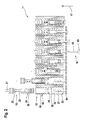
- FIG. 2 shows in a sectional view, the first embodiment in the FIG. 1 and the second embodiment in the FIG. 2 shown.
- Each of these figures shows in a series representation with joined sub-figures individual phases in the assembly of a first connector with a female contact and a subsequent insertion of a plug contact in the socket contact for closing the electrical connector.
- An electrical connector 11, according to the FIGS. 1 . 2 comprises a first connector 12, the socket contacts 13 and a second connector 14, the plug contacts 16 includes, which are insertable along a plug-in direction 17 in the associated socket contact 13.
- a contact carrier 18 of the first connector 12 11 arranged in rows receiving chambers 19 are arranged for the socket contacts 13 corresponding to the number of poles of the plug-in device.
- the socket contact 13 has for connection of an electrical conductor 21 a connecting portion 22, an adjoining locking portion 23 for fixing the position of the BuchungsWallets 13 in the receiving chamber 19 and a subsequent contact portion 24 for contacting with an associated male contact 16.
- the locking portion 23 occupies a reduced cross-sectional area with respect to the terminal portion 22 and the contact portion 24.
- FIG. 1 is in a first embodiment in a series representation with joined sub-figures, the assembly of a receiving chamber 19 by a socket contact 13 in the sequence of movement in a direction of insertion 17 opposing joining direction and the supply of one of the plug contacts 16 in the insertion direction 17 gradually shown progressively.
- the main body 26 has already passed through the feed opening 27 and is located for the most part in a sealing section 28 of the receiving chamber 19.
- An exposed end face 29 of the main body is already located in a centering funnel 31 adjacent to the sealing section 28 the preceding part of the figure uncovered and referred to here.
- the main body 26 is completely immersed in a bearing section 32, following the centering funnel 31, of the receiving chamber 19.
- the bearing portion 32 terminates at the end on a wall 33 which is pierced by an insertion opening 34, which widens in a funnel shape against the insertion direction 17.
- a laterally in the bearing portion 32 fixedly arranged spring-back locking arm 36 is biased by the base body 26 from its rest position, corresponding to the first two sub-figures, biased.
- wedge-shaped expansion element 37 is mounted on the wall. This is axially, in alignment with the plug-in direction 17, broken for a described in the following course passage of a plug-in contact 16.
- the spreader element 37 has penetrated into the contact section 24 so far that it can be rebated between two Contact blades 38 has arrived and this spread apart. Further, the latch arm 36 has returned to its rest position and blocked with a lying behind the main body 26 locking lug 39 a possible pushing out of the socket contact 13 from the receiving chamber 19th
- the feed movement of the socket contact 13 is closed in the receiving chamber 19 by a regurgitation of the end face 29 on the wall 33.
- a plug-in contact 34 directed towards the insertion opening 16 is fed to the socket contact 13 in the receiving chamber 19.
- the expansion element 37 reaches a region in which the distance of the contact blades 38 widens in a funnel shape, so that the influence of the expansion element 37 ends on the contact blades 38.
- the previously held contact blades 38 snap back and the contact between the contact blades 38 of the socket contact 13 and the plug contact 16 receives the desired high contact normal force.
- FIG. 2 is in a second embodiment in a series representation with joined sub-figures, the placement of a receiving chamber 19 by a female contact 13 in the movement in the joining direction 17 opposing joining direction and the supply of a plug-in contact 16 in the insertion direction 17 shown gradually progressing.
- the bar 43 detects a distance from an outer side of the wall 33 in the pre-locking position of the spreader 37 bottom plate 44 on which the spreader 37 is mounted perpendicular protruding and leads this bottom plate 44 to an end position when attacking the outside of the wall 33 with.
- the locking arm 36 secures with a locking lug 39 in this motion sequence here, as in the first embodiment, a pushing out of the contact portion 24 of the socket contact 13 against the joining direction of the bearing portion 32nd
Landscapes
- Connector Housings Or Holding Contact Members (AREA)
- Details Of Connecting Devices For Male And Female Coupling (AREA)
- Coupling Device And Connection With Printed Circuit (AREA)
Abstract
Description
- Die Erfindung geht aus von einer elektrischen Steckvorrichtung nach der Gattung des Anspruchs 1. Eine derartige Steckvorrichtung ist aus der
EP 0 273 999 B1 bekannt. - Bei einer Steckvorrichtung, die aus zwei zusammenfügbaren Steckverbindern besteht, ist die Kraft, die zum Zusammenfügen oder Trennen der beiden Steckverbinder benötigt wird, abhängig von der Anzahl der in der Steckvorrichtung jeweils paarweise zugeordneten Steckkontaktelementen.
- Für eine sichere elektrische Kontaktierung, insbesondere bei Vorliegen hoher Beanspruchungen der Steckvorrichtung z.B. durch Vibration und Temperaturschwankungen, wird eine Mindestkontaktnormalkraft benötigt, mit der der Kontaktbereich eines Buchsenkontakts auf einen messerförmigen Gegenkontakt aufgepresst wird. Somit ist zur Herstellung einer Steckverbindung eine Mindeststeckkraft für jeden einzelnen Kontakt erforderlich.
- Insbesondere bei hochpoligen Steckvorrichtungen mit einer großen Zahl von Kontakten resultiert aus der Steckkraft der Einzelkontakte eine Gesamtsteckkraft der Steckverbindung, die für den Anwender nur noch schwer aufzubringen ist.
- Aus der
EP 0 273 999 B1 ist bekannt, zur Überwindung der Gesamtsteckkraft der Steckvorrichtung eine Hilfsvorrichtung zu verwenden. Die Hilfsvorrichtung umfasst ein an einem der Steckverbinder gelagertes Handhabungsteil, das einseitig einen Ritzelbereich aufweist, dessen Zähne in einer Zahnstange in Eingriff sind, die bei einem Schwenken des Handhabungsteils in dem einen Steckverbinder verschiebbar ist. An der Zahnstange sind schräg zur Steckrichtung verlaufende Kulissennuten angebracht, die jeweils an einem, zum anderen Steckverbinder weisenden Endbereich offen sind und mit zugeordneten Nockenvorsprüngen am anderen der Steckverbinder in Eingriff gebracht werden können. - Durch diese Anordnung lassen sich die Gesamtsteckkräfte der Steckvorrichtung zwar reduzieren; jedoch ist durch den erforderlichen baulichen Aufwand die Steckvorrichtung großvolumig und in der Herstellung kostenintensiv.
- Die erfindungsgemäße elektrische Steckvorrichtung mit den kennzeichnenden Merkmalen des Anspruchs 1 hat demgegenüber den Vorteil, dass die zuvor erwähnten Unzulänglichkeiten in zufriedenstellendem Maß vermieden werden.
- Dazu wird zu Beginn des Kopplungsvorgangs der beiden Steckverbinder vor oder mit einer Einführung der Steckkontakte in die Buchsenkontakte durch wenigstens ein Spreizelement die Buchsenkontakte aufgespreizt. Damit lassen sich die Steckkontakte erleichtert in die Buchsenkontakte einführen und die Gesamtsteckkraft der Steckverbindung ist reduziert. Erst während oder im weiteren Verlauf der Einführung der Steckkontakte in die Buchsenkontakte wird die Aufspreizung zurückgeführt, so dass im Kontaktbereich die erforderliche Kontaktnormalkräfte zur Sicherung der elektrischen Verbindungen auftreten. Auf diese Weise lässt sich eine funktionssichere elektrische Steckvorrichtung realisieren, deren Gesamtsteckkraft gering ist und die dabei bei kleinem Volumen fertigungsgünstig herstellbar ist.
- In den Unteransprüchen sind vorteilhafte Maßnahmen für die Realisierung der Erfindung angegeben.
- Durch die Lagezuordnung des Buchsenkontakts zu einer Aufnahmekammer eines Kontaktträgers lässt sich der Buchsenkontakt gezielt kontaktieren.
- Mit der Ausbildung eines Spreizelements in der Aufnahmekammer wird der Buchsenkontakt schon im Laufe der Einführung in die Aufnahmekammer selbstständig, ohne einen separaten Aurbeitsschritt, aufgespreizt.
- Durch die Längsverschieblichkeit des Buchsenkontakts in der Aufnahmekammer lässt sich die Kopplung mit dem in der Aufnahmekammer angebrachten Spreizelement axial verändern.
- Mittels einer in dem Buchsenkontakt angebrachten Anlauffläche ist ein Element für eine Axialverschiebung des Buchsenkontakts durch einen eingeführten Steckkontakt gegeben.
- Durch eine Axialverschiebung des Buchsenkontakts in der Aufnahmekammer können die erforderliche Kontaktkräfte zur Sicherung der elektrischen Verbindungen wirksam werden.
- Mit dem Einführen eines der Aufnahmekammer zugeführten Spreizelements in den dort platzierten Buchsenkontakt kann ein bereits in der Aufnahmekammer befindlicher Buchsenkontakt aufgespreizt werden und diese Aufspreizung mit der nachfolgenden Einführung des Steckkontakts in die Aufnahmekammer rückgeführt werden.
- Mittels eines in der Aufnahmekammer angeordneten rückfederungsfähigen Rastarms lässt sich eine Axialverschiebung des Buchsenkontakts in der Aufnahmekammer begrenzen und so eine Sicherung der Überdeckung des Buchsenkontakts mit dem Steckkontakt erzielen.
- Durch die Ausgestaltung einer Rastkontur an dem Spreizelement kann ein vorbestimmter Aufspreizweg der Kontaktlamellen in fertigungstechnisch vorteilhafter Weise kraftgesteuert vorgenommen werden.
- Zwei Ausführungsbeispiele der Erfindung sind in der Zeichnung dargestellt und in der Figurenbeschreibung näher erläutert. Jeweils in einer Schnittdarstellung ist das erste Ausführungsbeispiel in der
Figur 1 und das zweite Ausführungsbeispiel in derFigur 2 dargestellt. Jede dieser Figuren zeigt in einer Reihendarstellung mit aneinandergefügten Teilfiguren einzelne Phasen bei der Bestückung eines ersten Steckverbinders mit einem Buchsenkontakt und eine nachfolgende Einführung eines Steckkontakts in den Buchsenkontakt zum Schließen der elektrischen Steckverbindung. - In den Figuren sind gleiche Bauteile und Bauteile mit gleicher Funktion mit den gleichen Bezugszeichen gekennzeichnet.
- Eine elektrische Steckvorrichtung 11, entsprechend den
Figuren 1 ,2 , umfaßt einen ersten Steckverbinder 12, der Buchsenkontakte 13 aufweist und einen zweiten Steckverbinder 14, der Steckkontakte 16 enthält, die entlang einer Steckrichtung 17 jeweils in den zugeordneten Buchsenkontakt 13 einführbar sind. - In einem Kontaktträger 18 des ersten Steckverbinders 12 sind entsprechend der Polzahl der Steckvorrichtung 11 in Reihen angeordnete Aufnahmekammern 19 für die Buchsenkontakte 13 angeordnet.
- Der Buchsenkontakt 13 weist zum Anschluß eines elektrischen Leiters 21 einen Anschlußabschnitt 22, einen daran anschließenden Verriegelungsabschnitt 23 zur Lagefixierung des Buchenkontakts 13 in der Aufnahmekammer 19 und einen darauf folgenden Kontaktabschnitt 24 zum Kontaktieren mit einem zugeordnetenSteckkontakt 16 auf. Der Verriegelungsabschnitt 23 nimmt gegenüber dem Anschlußabschnitt 22 und dem Kontaktabschnitt 24 eine verminderte Querschnittsfläche ein.
- In der
Figur 1 ist bei einem ersten Ausführungsbeispiel in einer Reihendarstellung mit aneinandergefügten Teilfiguren die Bestückung einer Aufnahmekammer 19 durch einen Buchsenkontakt 13 im Bewegungsablauf in einer der Steckrichtung 17 entgegengerichteten Fügerichtung und die Zuführung eines der Steckkontakte 16 in Steckrichtung 17 schrittweise fortfahrend gezeigt. - In der ersten Teilfigur links außen ist der Buchsenkontakt 13 noch außerhalb der Aufnahmekammer 19 angeordnet. Dabei ist der Kontaktabschnitt 24 des Buchsenkontakts mit einem außenliegenden kastenförmigen Grundkörper 26 einer Zuführöffnung 27 der Aufnahmekammer 19 fluchtend zur Steckrichtung 17 zugewandt.
- In der zweiten Teilfigur von links ist der Grundkörper 26 bereits durch die Zuführöffnung 27 hindurchgetreten und befindet sich größtenteils in einem Dichtabschnitt 28 der Aufnahmekammer 19. Eine freiliegende Stirnseite 29 des Grundkörpers befindet sich bereits in einem, an den Dichtabschnitt 28 angrenzenden Zentriertrichter 31, der in der vorgehenden Teilfigur unverdeckt dargestellt und hier bezeichnet ist.
- In der dritten Teilfigur von links ist der Grundkörper 26 vollständig in einen, dem Zentriertrichter 31 nachfolgenden Lagerabschnitt 32 der Aufnahmekammer 19 eingetaucht. Der Lagerabschnitt 32 endet stirnseitig an einer Wand 33, die von einer Einstecköffnung 34 durchbrochen ist, die sich gegen die Steckrichtung 17 trichterförmig erweitert. Ein seitlich in dem Lagerabschnitt 32 fest angeordneter rückfederungsfähiger Rastarm 36 ist durch den Grundkörper 26 aus seiner Ruhelage, entsprechend den ersten beiden Teilfiguren, vorgespannt ausgelenkt.
- Über der Einstecköffnung ist auf der Wand 33 ein in den Lagerabschnitt 32 ragendes keilförmiges Spreizelement 37 angebracht. Dieses ist axial, in Flucht zur Steckrichtung 17, für einen, im nachfolgenden Verlauf beschriebenen Durchtritt eines Steckkontakts 16 durchbrochen.
- In der 4. Teilfigur von links ist das Spreizelement 37 soweit in den Kontaktabschnitt 24 eingedrungen, dass es zwischen zwei ausfederungsfähigen Kontaktlamellen 38 gelangt ist und diese auseinanderspreizt. Ferner ist der Rastarm 36 in seine Ruhelage zurückgekehrt und blockiert mit einer hinter dem Grundkörper 26 liegenden Rastnase 39 ein mögliches Ausschieben des Buchsenkontakts 13 aus der Aufnahmekammer 19.
- In der 5. Teilfigur von links ist die Zuführbewegung des Buchsenkontakts 13 in die Aufnahmekammer 19 durch ein Aufstoßen der Stirnseite 29 an der Wand 33 abgeschlossen.
- In der 6. Teilfigur von links wird ein auf die Einstecköffnung 34 gerichteter Steckkontakt 16 dem Buchsenkontakt 13 in der Aufnahmekammer 19 zugeführt.
- In der 7. Teilfigur von links ist der Steckkontakt 16 über eine Teillänge durch den Zentriertrichter 31 geführt und ragt endseitig in den aufgespreizten Bereich der Kontaktlamellen 38 hinein.
- Nach einer weitergeführten Zuführbewegung des Steckkontakts 16 entsprechend der 8. Teilfigur von links ist der Steckkontakt 16 endseitig in Anlage an eine fest in dem Kontaktabschnitt 24 des Buchsenkontaktes 13 angebrachte, lotrecht zur Steckrichtung ausgerichtete Anlauffläche 41 gelangt und der Buchsenkontakt 13 wird im weiteren Verlauf der Zuführbewegung in der Aufnahmekammer 19 axial in Steckrichtung 17 verschoben. Damit gelangt das Spreizelement 37 in einen Bereich, in dem der Abstand der Kontaktlamellen 38 sich trichterförmig erweitert, so dass der Einfluß des Spreizelements 37 auf die Kontaktlamellen 38 endet. Dadurch schnappen die zuvor aufgehaltenen Kontaktlamellen 38 zurück und der Kontakt zwischen den Kontaktlamellen 38 des Buchsenkontakts 13 und dem Steckkontakt 16 erhält die gewünschte hohe Kontaktnormalkraft.
- Die rückwärtige Axialverschiebung des Buchsenkontakts 13 in der Aufnahmekammer 19 endet entsprechend der 9. Teilfigur von links mit einem Anschlag einer Rückseite 42 des Kontaktabschnitts 24 an der Rastnase 39.
- In der
Figur 2 ist bei einem zweiten Ausführungsbeispiel in einer Reihendarstellung mit aneinandergefügten Teilfiguren die Bestückung einer Aufnahmekammer 19 durch einen Buchsenkontakt 13 im Bewegungsablauf in der der Steckrichtung 17 entgegengerichteten Fügerichtung und die Zuführung eines Steckkontaktes 16 in Steckrichtung 17 schrittweise fortfahrend gezeigt. - Abweichend von dem ersten Ausführungsbeispiel ist weder in dem Lagerabschnitt 32 der Aufnahmekammer 19 ein ortsfestes Spreizelement 37, noch in dem Kontaktabschnitt 24 des Buchsenkontakts 13 eine Anlauffläche 41 angebracht. Vielmehr wird vor Einführung des Steckkontakts 16 in den Buchsenkontakt 13 ein hohlkammerförmiges Spreizelement 37, dessen Ausformung einen späteren Durchtritt des Steckkontakts 16 erlaubt, in Steckrichtung 17 durch die Einstecköffnung 34 der Aufnahmekammer 19 über eine Teillänge in den Lagerabschnitt 32 eingebracht und in nicht näher dargestellter Weise in einer Vorraststellung fixiert.
- Danach erfolgt eine Einführung des Buchsenkontaktes 13 in die Aufnahmekammer 19, wie zu den ersten fünf Teilfiguren der
Figur 1 beschrieben und in den ersten vier Teilfiguren derFigur 2 dargestellt. Damit sind die Kontaktlamellen 38, vorbereitet für die Einführung des jeweiligen Steckkontaktes 16, durch das Auflaufen der Kontaktlamellen 38 auf das Spreizelement 37 aufgespreizt. - Entsprechend der
Figur 2 mit den Teilfiguren 5-8 von links wird der Steckkontakt 16, der aus einer Leiste 43 des zweiten Steckverbinders 14 herausragt, fortschreitend in den Lagerabschnitt 32 des Buchsenkontaktes 13 in Steckrichtung 17 eingeführt. Dabei gelangt das freie Ende des stiftförmigen Steckkontakts 16 durch das Spreizelement 37 hindurch zwischen die aufgespreizten Kontaktlamellen 38. - Danach erfasst die Leiste 43 eine von einer Außenseite der Wand 33 in der Vorraststellung des Spreizelements 37 distanzierte Bodenplatte 44, auf der das Spreizelement 37 lotrecht hervorstehend gelagert ist und führt diese Bodenplatte 44 bis zu einer Endstellung beim Anschlag an die Außenseite der Wand 33 mit.
- Durch die Verlagerung der Bodenplatte 44 wird auch das darauf befindliche Spreizelement 37 mitbewegt und es gelangt dabei in den Bereich, in dem sich der Abstand der Kontaktlamellen 38 trichterförmig erweitert, so dass der Einfluß des Spreizelements 37 auf die Kontaktlamellen 38 endet. Dadurch schnappen die zuvor aufgespreizten Kontaktlamellen 38 zurück und der Kontakt zwischen den Kontaktlamellen 38 des Buchsenkontakts 13 und dem Steckkontakt 16 erhält die gewünschte hohe Kontaktnormalkraft.
- Der Rastarm 36 sichert mit einer Rastnase 39 bei diesem Bewegungsablauf auch hier, wie beim 1. Ausführungselement, ein Ausschieben des Kontaktabschnitts 24 des Buchsenkontaktes 13 entgegen der Fügerichtung aus dem Lagerabschnitt 32.
- Mit der Ausgestaltung der elektrischen Steckverbindung entsprechend den beiden Ausführungsbeispielen ist es möglich, die Steckkraft und die Kontaktnormalkraft voneinander unabhängig auszubilden in dem Sinne, dass durch die aufgespreizten Kontaktlamellen 38 die Steckkraft gering ausfällt und durch die anschließende Verlagerung des Spreizelements 37 in eine Nichteingriffslage eine gewünschte hohe Kontaktnormalkraft zwischen den Kontaktlamellen 38 und dem Steckkontakt 16 erlangt wird.
Claims (10)
- Elektrische Steckvorrichtung mit einem ersten Steckverbinder (12) und einem damit koppelbaren zweiten Steckverbinder (14), wobei der erste Steckverbinder (12) Buchsenkontakte (13) und der zweite Steckverbinder (14) Steckkontakte (16) aufweist und bei der Kopplung der beiden Steckverbinder (12), (14) zum Schließen der elektrischen Steckvorrichtung (11) die Steckkontakte (16) mit den Buchsenkontakten (18) zusammengeführt werden, dadurch gekennzeichnet, dass zu Beginn des Kopplungsvorgangs der beiden Steckverbinder (12), (14) entlang einer Steckrichtung (17) vor oder mit einer Einführung der Steckkontakte (16) in die Buchsenkontakte (13) durch wenigstens ein Spreizelement (37) die Buchsenkontakte (13) zur Erleichterung der Einführung der Steckkontakte (16) aufgespreizt werden und diese Aufspreizung erst während oder im weiteren Verlauf der Einführung der Steckkontakte (16) in die Buchsenkontakte (13) zurückgeführt wird.
- Steckverbindung nach Anspruch 1, dadurch gekennzeichnet, dass die Buchsenkontakte (13) jeweils einen Anschlußabschnitt (22) zum Anschluß eines elektrischen Leiters (21), einen Kontaktabschnitt (24) zum Kontaktieren mit einem zugeodneten Steckkontakt (16) und einen Verriegelungsabschnitt (23) enthalten, der gegenüber dem Anschlußabschnitt (22) und dem Kontaktabschnitt (24) eine verminderte Querschnittsfläche zur Lagefixierung des Buchsenkontakts (13) in einer Aufnahmekammer (19) eines Kontaktträgers (18) des ersten Steckverbinders (12) aufweist.
- Steckverbindung nach Anspruch 2, dadurch gekennzeichnet, dass in der Aufnahmekammer (19) wenigstens ein Spreizelement (37) als Teil der Aufnahmekammer (19) angebracht ist, das beim Einführen des Buchsenkontakts (13) in die Aufnahmekammer (19) diesen zumindest bereichsweise aufspreizt.
- Steckverbindung nach Anspruch 3, dadurch gekennzeichnet, dass der Buchsenkontakt (13) in der Aufnahmekammer (19) axial, in Flucht zur Steckrichtung (17), längsverschieblich ist.
- Steckverbindung nach Anspruch 4, dadurch gekennzeichnet, dass in dem Buchsenkontakt (13) eine Anlauffläche (41) für den zugeordneten Steckkontakt (16) angebracht ist und nach einem Anlaufen des Steckkontakts (16) an der Anlauffläche (41) bei einer weitergeführten Zuführbewegung des Steckkontakts (16) eine Axialverschiebung des Buchsenkontakts (13) erfolgt.
- Steckverbindung nach Anspruch 5, dadurch gekennzeichnet, dass mit der Axialverschiebung des Buchsenkontakts (13) durch den Steckkontakt (16) der Buchsenkontakt (13) aus dem Eingriff des Spreizelements (37) gelöst wird und rückfedernd eine Anlage oder eine verstärkte Anpressung des Buchsenkontakts (13) an dem Steckkontakt (16) erfolgt.
- Steckverbindung nach Anspruch 2, dadurch gekennzeichnet, dass vor einem Einführen des Steckkontakts (16) in den, in der Aufnahmekammer (19) angeordneten Buchsenkontakt (13) wenigstens ein Spreizelement (37) in den Buchsenkontakt ((13) zu dessen Aufspreizung eingeführt wird, das mit dem Zuführen des Steckkontakts (16) in den Buchsenkontakt (13) längs der Steckrichtung (17) durch den Steckkontakt (16) verschiebbar ist und bei einer weitergeführten Zuführbewegung des Steckkontakts (16) in den Buchsenkontakt (13) hinsichtlich der Aufspreizung des Buchsenkontakts (13) außer Eingriff mit dem Buchsenkontakt (13) kommt.
- Steckverbindung nach einem der Ansprüche 2-7, dadurch gekennzeichnet, dass der Kontaktabschnitt (24) einen kastenförmigen Grundkörper (26) aufweist, in dem Kontaktlamellen (38) angeordnet sind, die durch das Spreizelement (37) rückfedernd aufweitbar sind und die nach einer Rückfederung unter Vermittlung einer Kontaktnormalkraft gegen den Steckkontakt (16) pressen.
- Steckverbindung nach Anspruch 8, dadurch gekennzeichnet, dass in der Aufnahmekammer (19) ein rückfedernder Rastarm (36) angeordnet ist, der bei einem Einführen des Buchsenkontakts (13) in die Aufnahmekammer (19) ausgelenkt wird und der nach der Rückfederung ein Zurückschieben des Buchsenkontakts (13) aus der Aufnahmekammer durch einen Hintergriff des Grundkörpers (26) im Bereich des Verriegelungsabschnitts (23) formschlüssig unterbindet.
- Steckverbindung nach Anspruch 9, dadurch gekennzeichnet, dass das Spreizelement (37) eine Rastkontur aufweist, in der die Kontaktlamellen (38) lösbar einrastbar sind.
Applications Claiming Priority (1)
| Application Number | Priority Date | Filing Date | Title |
|---|---|---|---|
| DE102008002592A DE102008002592A1 (de) | 2008-06-24 | 2008-06-24 | Elektrische Steckvorrichtung |
Publications (2)
| Publication Number | Publication Date |
|---|---|
| EP2139076A1 true EP2139076A1 (de) | 2009-12-30 |
| EP2139076B1 EP2139076B1 (de) | 2011-10-05 |
Family
ID=40909967
Family Applications (1)
| Application Number | Title | Priority Date | Filing Date |
|---|---|---|---|
| EP09100256A Not-in-force EP2139076B1 (de) | 2008-06-24 | 2009-04-29 | Elektrische Steckvorrichtung |
Country Status (3)
| Country | Link |
|---|---|
| EP (1) | EP2139076B1 (de) |
| AT (1) | ATE527725T1 (de) |
| DE (1) | DE102008002592A1 (de) |
Families Citing this family (2)
| Publication number | Priority date | Publication date | Assignee | Title |
|---|---|---|---|---|
| DE202017002766U1 (de) | 2017-05-24 | 2017-06-16 | Berthold W. Seemann | Vorrichtung zur Abschreckung von Maulwürfen mittels Schall |
| DE202018001188U1 (de) | 2018-03-06 | 2018-03-23 | Berthold W. Seemann | Vibrator zur Vergrämung von Maulwürfen |
Citations (6)
| Publication number | Priority date | Publication date | Assignee | Title |
|---|---|---|---|---|
| EP0273999B1 (de) | 1987-01-05 | 1993-09-29 | The Whitaker Corporation | Verbinderanordnung mit Anhebe-Zahnstange |
| EP0658952A1 (de) * | 1993-12-15 | 1995-06-21 | Connecteurs Cinch | Elektrische Kontaktbuchse und Verbindergehäuse zur Aufnahme einer solchen Buchse |
| DE102005043417A1 (de) * | 2005-09-13 | 2007-03-15 | Robert Bosch Gmbh | Steckverbinder, Buchsenkontakt und Verriegelungselement für den Steckverbinder zur Herstellung einer elektrischen Steckverbindung |
| DE102005043158A1 (de) * | 2005-09-12 | 2007-03-15 | Robert Bosch Gmbh | Buchsenkontakt mit eigenständigem Primärverrastungsteil |
| EP1764875A1 (de) * | 2005-09-14 | 2007-03-21 | Robert Bosch Gmbh | Elektrischer Steckverbinder mit vorgespannten Kontaktlamellen |
| FR2896628A1 (fr) * | 2006-01-23 | 2007-07-27 | Tyco Electronics Amp Kk | Connecteur electrique de type flottant |
-
2008
- 2008-06-24 DE DE102008002592A patent/DE102008002592A1/de not_active Withdrawn
-
2009
- 2009-04-29 AT AT09100256T patent/ATE527725T1/de active
- 2009-04-29 EP EP09100256A patent/EP2139076B1/de not_active Not-in-force
Patent Citations (6)
| Publication number | Priority date | Publication date | Assignee | Title |
|---|---|---|---|---|
| EP0273999B1 (de) | 1987-01-05 | 1993-09-29 | The Whitaker Corporation | Verbinderanordnung mit Anhebe-Zahnstange |
| EP0658952A1 (de) * | 1993-12-15 | 1995-06-21 | Connecteurs Cinch | Elektrische Kontaktbuchse und Verbindergehäuse zur Aufnahme einer solchen Buchse |
| DE102005043158A1 (de) * | 2005-09-12 | 2007-03-15 | Robert Bosch Gmbh | Buchsenkontakt mit eigenständigem Primärverrastungsteil |
| DE102005043417A1 (de) * | 2005-09-13 | 2007-03-15 | Robert Bosch Gmbh | Steckverbinder, Buchsenkontakt und Verriegelungselement für den Steckverbinder zur Herstellung einer elektrischen Steckverbindung |
| EP1764875A1 (de) * | 2005-09-14 | 2007-03-21 | Robert Bosch Gmbh | Elektrischer Steckverbinder mit vorgespannten Kontaktlamellen |
| FR2896628A1 (fr) * | 2006-01-23 | 2007-07-27 | Tyco Electronics Amp Kk | Connecteur electrique de type flottant |
Also Published As
| Publication number | Publication date |
|---|---|
| ATE527725T1 (de) | 2011-10-15 |
| EP2139076B1 (de) | 2011-10-05 |
| DE102008002592A1 (de) | 2009-12-31 |
Similar Documents
| Publication | Publication Date | Title |
|---|---|---|
| DE68909838T2 (de) | Doppeleinfügungsstruktur für Anschlussklemmen in Steckverbindern. | |
| DE60121656T2 (de) | Ständer und automatische Maschine zur Schneidklemmverbindung | |
| DE69405782T2 (de) | Verbinder | |
| DE69819057T2 (de) | Verbinder | |
| EP3329558B1 (de) | Elektrischer steckverbinder | |
| EP0554810A2 (de) | Elektrischer Verbinder | |
| DE69415951T2 (de) | Verbinderanordnung | |
| DE3705739C2 (de) | Elektrische Verbinderanordnung | |
| DE29716767U1 (de) | Flachsteckhülse zum elektrischen Verbinden eines eine abisolierte Litze aufweisenden Kabels o.dgl. mit einem Flachstecker | |
| DE102006030784B4 (de) | Steckverbinder mit einer Sekundärverriegelung | |
| EP3375048A1 (de) | Steckkontakt | |
| DE69118145T2 (de) | Halterungsaufbau für metallische Anschlussklemme | |
| DE69411772T2 (de) | Elektrischer Verbinder mit Kontaktrückhaltemitteln | |
| DE102023105968A1 (de) | Geschirmter PushPull-Stecker mit Schirmfeder | |
| EP3288121A1 (de) | Komplett abgedichteter steckverbinder mit verbesserten haltekräften | |
| EP1764875B1 (de) | Elektrischer Steckverbinder mit vorgespannten Kontaktlamellen | |
| EP2139076B1 (de) | Elektrische Steckvorrichtung | |
| DE102012106741B4 (de) | Kontaktelement | |
| DE2842892A1 (de) | Elektrischer verbinder | |
| DE19949386C2 (de) | Geräte-Anschlusskasten mit Schneidtechnik | |
| DE10111473B4 (de) | Verbinder | |
| EP2026416B1 (de) | Kabelaufnahmevorrichtung und Kontaktsystem | |
| DE102013110512B4 (de) | Steckverbinder mit Primär- und Sekundärverriegelung | |
| DE102008042610A1 (de) | Elektrische Steckvorrichtung | |
| DE69608557T2 (de) | Zeitliche anschlussrückhaltung |
Legal Events
| Date | Code | Title | Description |
|---|---|---|---|
| PUAI | Public reference made under article 153(3) epc to a published international application that has entered the european phase |
Free format text: ORIGINAL CODE: 0009012 |
|
| AK | Designated contracting states |
Kind code of ref document: A1 Designated state(s): AT BE BG CH CY CZ DE DK EE ES FI FR GB GR HR HU IE IS IT LI LT LU LV MC MK MT NL NO PL PT RO SE SI SK TR |
|
| 17P | Request for examination filed |
Effective date: 20100630 |
|
| 17Q | First examination report despatched |
Effective date: 20100716 |
|
| GRAP | Despatch of communication of intention to grant a patent |
Free format text: ORIGINAL CODE: EPIDOSNIGR1 |
|
| GRAS | Grant fee paid |
Free format text: ORIGINAL CODE: EPIDOSNIGR3 |
|
| GRAA | (expected) grant |
Free format text: ORIGINAL CODE: 0009210 |
|
| AK | Designated contracting states |
Kind code of ref document: B1 Designated state(s): AT BE BG CH CY CZ DE DK EE ES FI FR GB GR HR HU IE IS IT LI LT LU LV MC MK MT NL NO PL PT RO SE SI SK TR |
|
| REG | Reference to a national code |
Ref country code: GB Ref legal event code: FG4D Free format text: NOT ENGLISH |
|
| REG | Reference to a national code |
Ref country code: CH Ref legal event code: EP |
|
| REG | Reference to a national code |
Ref country code: IE Ref legal event code: FG4D |
|
| REG | Reference to a national code |
Ref country code: DE Ref legal event code: R096 Ref document number: 502009001503 Country of ref document: DE Effective date: 20111201 |
|
| REG | Reference to a national code |
Ref country code: NL Ref legal event code: VDEP Effective date: 20111005 |
|
| PG25 | Lapsed in a contracting state [announced via postgrant information from national office to epo] |
Ref country code: SI Free format text: LAPSE BECAUSE OF FAILURE TO SUBMIT A TRANSLATION OF THE DESCRIPTION OR TO PAY THE FEE WITHIN THE PRESCRIBED TIME-LIMIT Effective date: 20111005 |
|
| LTIE | Lt: invalidation of european patent or patent extension |
Effective date: 20111005 |
|
| PG25 | Lapsed in a contracting state [announced via postgrant information from national office to epo] |
Ref country code: IS Free format text: LAPSE BECAUSE OF FAILURE TO SUBMIT A TRANSLATION OF THE DESCRIPTION OR TO PAY THE FEE WITHIN THE PRESCRIBED TIME-LIMIT Effective date: 20120205 Ref country code: LT Free format text: LAPSE BECAUSE OF FAILURE TO SUBMIT A TRANSLATION OF THE DESCRIPTION OR TO PAY THE FEE WITHIN THE PRESCRIBED TIME-LIMIT Effective date: 20111005 Ref country code: NO Free format text: LAPSE BECAUSE OF FAILURE TO SUBMIT A TRANSLATION OF THE DESCRIPTION OR TO PAY THE FEE WITHIN THE PRESCRIBED TIME-LIMIT Effective date: 20120105 |
|
| REG | Reference to a national code |
Ref country code: IE Ref legal event code: FD4D |
|
| PG25 | Lapsed in a contracting state [announced via postgrant information from national office to epo] |
Ref country code: LV Free format text: LAPSE BECAUSE OF FAILURE TO SUBMIT A TRANSLATION OF THE DESCRIPTION OR TO PAY THE FEE WITHIN THE PRESCRIBED TIME-LIMIT Effective date: 20111005 Ref country code: NL Free format text: LAPSE BECAUSE OF FAILURE TO SUBMIT A TRANSLATION OF THE DESCRIPTION OR TO PAY THE FEE WITHIN THE PRESCRIBED TIME-LIMIT Effective date: 20111005 Ref country code: GR Free format text: LAPSE BECAUSE OF FAILURE TO SUBMIT A TRANSLATION OF THE DESCRIPTION OR TO PAY THE FEE WITHIN THE PRESCRIBED TIME-LIMIT Effective date: 20120106 Ref country code: PT Free format text: LAPSE BECAUSE OF FAILURE TO SUBMIT A TRANSLATION OF THE DESCRIPTION OR TO PAY THE FEE WITHIN THE PRESCRIBED TIME-LIMIT Effective date: 20120206 Ref country code: HR Free format text: LAPSE BECAUSE OF FAILURE TO SUBMIT A TRANSLATION OF THE DESCRIPTION OR TO PAY THE FEE WITHIN THE PRESCRIBED TIME-LIMIT Effective date: 20111005 Ref country code: SE Free format text: LAPSE BECAUSE OF FAILURE TO SUBMIT A TRANSLATION OF THE DESCRIPTION OR TO PAY THE FEE WITHIN THE PRESCRIBED TIME-LIMIT Effective date: 20111005 |
|
| PG25 | Lapsed in a contracting state [announced via postgrant information from national office to epo] |
Ref country code: CY Free format text: LAPSE BECAUSE OF FAILURE TO SUBMIT A TRANSLATION OF THE DESCRIPTION OR TO PAY THE FEE WITHIN THE PRESCRIBED TIME-LIMIT Effective date: 20111005 |
|
| PG25 | Lapsed in a contracting state [announced via postgrant information from national office to epo] |
Ref country code: CZ Free format text: LAPSE BECAUSE OF FAILURE TO SUBMIT A TRANSLATION OF THE DESCRIPTION OR TO PAY THE FEE WITHIN THE PRESCRIBED TIME-LIMIT Effective date: 20111005 Ref country code: IE Free format text: LAPSE BECAUSE OF FAILURE TO SUBMIT A TRANSLATION OF THE DESCRIPTION OR TO PAY THE FEE WITHIN THE PRESCRIBED TIME-LIMIT Effective date: 20111005 Ref country code: SK Free format text: LAPSE BECAUSE OF FAILURE TO SUBMIT A TRANSLATION OF THE DESCRIPTION OR TO PAY THE FEE WITHIN THE PRESCRIBED TIME-LIMIT Effective date: 20111005 Ref country code: BG Free format text: LAPSE BECAUSE OF FAILURE TO SUBMIT A TRANSLATION OF THE DESCRIPTION OR TO PAY THE FEE WITHIN THE PRESCRIBED TIME-LIMIT Effective date: 20120105 Ref country code: EE Free format text: LAPSE BECAUSE OF FAILURE TO SUBMIT A TRANSLATION OF THE DESCRIPTION OR TO PAY THE FEE WITHIN THE PRESCRIBED TIME-LIMIT Effective date: 20111005 Ref country code: DK Free format text: LAPSE BECAUSE OF FAILURE TO SUBMIT A TRANSLATION OF THE DESCRIPTION OR TO PAY THE FEE WITHIN THE PRESCRIBED TIME-LIMIT Effective date: 20111005 |
|
| PLBE | No opposition filed within time limit |
Free format text: ORIGINAL CODE: 0009261 |
|
| STAA | Information on the status of an ep patent application or granted ep patent |
Free format text: STATUS: NO OPPOSITION FILED WITHIN TIME LIMIT |
|
| PG25 | Lapsed in a contracting state [announced via postgrant information from national office to epo] |
Ref country code: RO Free format text: LAPSE BECAUSE OF FAILURE TO SUBMIT A TRANSLATION OF THE DESCRIPTION OR TO PAY THE FEE WITHIN THE PRESCRIBED TIME-LIMIT Effective date: 20111005 Ref country code: PL Free format text: LAPSE BECAUSE OF FAILURE TO SUBMIT A TRANSLATION OF THE DESCRIPTION OR TO PAY THE FEE WITHIN THE PRESCRIBED TIME-LIMIT Effective date: 20111005 |
|
| 26N | No opposition filed |
Effective date: 20120706 |
|
| BERE | Be: lapsed |
Owner name: ROBERT BOSCH G.M.B.H. Effective date: 20120430 |
|
| REG | Reference to a national code |
Ref country code: DE Ref legal event code: R097 Ref document number: 502009001503 Country of ref document: DE Effective date: 20120706 |
|
| PG25 | Lapsed in a contracting state [announced via postgrant information from national office to epo] |
Ref country code: MC Free format text: LAPSE BECAUSE OF NON-PAYMENT OF DUE FEES Effective date: 20120430 |
|
| PG25 | Lapsed in a contracting state [announced via postgrant information from national office to epo] |
Ref country code: BE Free format text: LAPSE BECAUSE OF NON-PAYMENT OF DUE FEES Effective date: 20120430 |
|
| PG25 | Lapsed in a contracting state [announced via postgrant information from national office to epo] |
Ref country code: MK Free format text: LAPSE BECAUSE OF FAILURE TO SUBMIT A TRANSLATION OF THE DESCRIPTION OR TO PAY THE FEE WITHIN THE PRESCRIBED TIME-LIMIT Effective date: 20111005 |
|
| PG25 | Lapsed in a contracting state [announced via postgrant information from national office to epo] |
Ref country code: ES Free format text: LAPSE BECAUSE OF FAILURE TO SUBMIT A TRANSLATION OF THE DESCRIPTION OR TO PAY THE FEE WITHIN THE PRESCRIBED TIME-LIMIT Effective date: 20120116 |
|
| PG25 | Lapsed in a contracting state [announced via postgrant information from national office to epo] |
Ref country code: FI Free format text: LAPSE BECAUSE OF FAILURE TO SUBMIT A TRANSLATION OF THE DESCRIPTION OR TO PAY THE FEE WITHIN THE PRESCRIBED TIME-LIMIT Effective date: 20111005 |
|
| PG25 | Lapsed in a contracting state [announced via postgrant information from national office to epo] |
Ref country code: MT Free format text: LAPSE BECAUSE OF FAILURE TO SUBMIT A TRANSLATION OF THE DESCRIPTION OR TO PAY THE FEE WITHIN THE PRESCRIBED TIME-LIMIT Effective date: 20111005 |
|
| REG | Reference to a national code |
Ref country code: CH Ref legal event code: PL |
|
| GBPC | Gb: european patent ceased through non-payment of renewal fee |
Effective date: 20130429 |
|
| PG25 | Lapsed in a contracting state [announced via postgrant information from national office to epo] |
Ref country code: GB Free format text: LAPSE BECAUSE OF NON-PAYMENT OF DUE FEES Effective date: 20130429 Ref country code: CH Free format text: LAPSE BECAUSE OF NON-PAYMENT OF DUE FEES Effective date: 20130430 Ref country code: LI Free format text: LAPSE BECAUSE OF NON-PAYMENT OF DUE FEES Effective date: 20130430 |
|
| PG25 | Lapsed in a contracting state [announced via postgrant information from national office to epo] |
Ref country code: TR Free format text: LAPSE BECAUSE OF FAILURE TO SUBMIT A TRANSLATION OF THE DESCRIPTION OR TO PAY THE FEE WITHIN THE PRESCRIBED TIME-LIMIT Effective date: 20111005 |
|
| PG25 | Lapsed in a contracting state [announced via postgrant information from national office to epo] |
Ref country code: LU Free format text: LAPSE BECAUSE OF NON-PAYMENT OF DUE FEES Effective date: 20120429 |
|
| PG25 | Lapsed in a contracting state [announced via postgrant information from national office to epo] |
Ref country code: HU Free format text: LAPSE BECAUSE OF FAILURE TO SUBMIT A TRANSLATION OF THE DESCRIPTION OR TO PAY THE FEE WITHIN THE PRESCRIBED TIME-LIMIT Effective date: 20090429 |
|
| REG | Reference to a national code |
Ref country code: AT Ref legal event code: MM01 Ref document number: 527725 Country of ref document: AT Kind code of ref document: T Effective date: 20140429 |
|
| PG25 | Lapsed in a contracting state [announced via postgrant information from national office to epo] |
Ref country code: AT Free format text: LAPSE BECAUSE OF NON-PAYMENT OF DUE FEES Effective date: 20140429 |
|
| REG | Reference to a national code |
Ref country code: FR Ref legal event code: PLFP Year of fee payment: 8 |
|
| REG | Reference to a national code |
Ref country code: FR Ref legal event code: PLFP Year of fee payment: 9 |
|
| REG | Reference to a national code |
Ref country code: FR Ref legal event code: PLFP Year of fee payment: 10 |
|
| PGFP | Annual fee paid to national office [announced via postgrant information from national office to epo] |
Ref country code: FR Payment date: 20200421 Year of fee payment: 12 |
|
| PGFP | Annual fee paid to national office [announced via postgrant information from national office to epo] |
Ref country code: IT Payment date: 20200423 Year of fee payment: 12 |
|
| PG25 | Lapsed in a contracting state [announced via postgrant information from national office to epo] |
Ref country code: FR Free format text: LAPSE BECAUSE OF NON-PAYMENT OF DUE FEES Effective date: 20210430 |
|
| PG25 | Lapsed in a contracting state [announced via postgrant information from national office to epo] |
Ref country code: IT Free format text: LAPSE BECAUSE OF NON-PAYMENT OF DUE FEES Effective date: 20200429 |
|
| PGFP | Annual fee paid to national office [announced via postgrant information from national office to epo] |
Ref country code: DE Payment date: 20230627 Year of fee payment: 15 |
|
| REG | Reference to a national code |
Ref country code: DE Ref legal event code: R119 Ref document number: 502009001503 Country of ref document: DE |
|
| PG25 | Lapsed in a contracting state [announced via postgrant information from national office to epo] |
Ref country code: DE Free format text: LAPSE BECAUSE OF NON-PAYMENT OF DUE FEES Effective date: 20241105 |
|
| PG25 | Lapsed in a contracting state [announced via postgrant information from national office to epo] |
Ref country code: DE Free format text: LAPSE BECAUSE OF NON-PAYMENT OF DUE FEES Effective date: 20241105 |
|
| PG25 | Lapsed in a contracting state [announced via postgrant information from national office to epo] |
Ref country code: IT Free format text: LAPSE BECAUSE OF NON-PAYMENT OF DUE FEES Effective date: 20210429 |