EP2139076A1 - Dispositif de raccordement électrique - Google Patents
Dispositif de raccordement électrique Download PDFInfo
- Publication number
- EP2139076A1 EP2139076A1 EP09100256A EP09100256A EP2139076A1 EP 2139076 A1 EP2139076 A1 EP 2139076A1 EP 09100256 A EP09100256 A EP 09100256A EP 09100256 A EP09100256 A EP 09100256A EP 2139076 A1 EP2139076 A1 EP 2139076A1
- Authority
- EP
- European Patent Office
- Prior art keywords
- contact
- plug
- socket
- contacts
- receiving chamber
- Prior art date
- Legal status (The legal status is an assumption and is not a legal conclusion. Google has not performed a legal analysis and makes no representation as to the accuracy of the status listed.)
- Granted
Links
Images

Classifications
-
- H—ELECTRICITY
- H01—ELECTRIC ELEMENTS
- H01R—ELECTRICALLY-CONDUCTIVE CONNECTIONS; STRUCTURAL ASSOCIATIONS OF A PLURALITY OF MUTUALLY-INSULATED ELECTRICAL CONNECTING ELEMENTS; COUPLING DEVICES; CURRENT COLLECTORS
- H01R13/00—Details of coupling devices of the kinds covered by groups H01R12/70 or H01R24/00 - H01R33/00
- H01R13/02—Contact members
- H01R13/193—Means for increasing contact pressure at the end of engagement of coupling part, e.g. zero insertion force or no friction
-
- H—ELECTRICITY
- H01—ELECTRIC ELEMENTS
- H01R—ELECTRICALLY-CONDUCTIVE CONNECTIONS; STRUCTURAL ASSOCIATIONS OF A PLURALITY OF MUTUALLY-INSULATED ELECTRICAL CONNECTING ELEMENTS; COUPLING DEVICES; CURRENT COLLECTORS
- H01R13/00—Details of coupling devices of the kinds covered by groups H01R12/70 or H01R24/00 - H01R33/00
- H01R13/02—Contact members
- H01R13/10—Sockets for co-operation with pins or blades
- H01R13/11—Resilient sockets
- H01R13/112—Resilient sockets forked sockets having two legs
-
- H—ELECTRICITY
- H01—ELECTRIC ELEMENTS
- H01R—ELECTRICALLY-CONDUCTIVE CONNECTIONS; STRUCTURAL ASSOCIATIONS OF A PLURALITY OF MUTUALLY-INSULATED ELECTRICAL CONNECTING ELEMENTS; COUPLING DEVICES; CURRENT COLLECTORS
- H01R13/00—Details of coupling devices of the kinds covered by groups H01R12/70 or H01R24/00 - H01R33/00
- H01R13/40—Securing contact members in or to a base or case; Insulating of contact members
- H01R13/42—Securing in a demountable manner
- H01R13/422—Securing in resilient one-piece base or case, e.g. by friction; One-piece base or case formed with resilient locking means
- H01R13/4223—Securing in resilient one-piece base or case, e.g. by friction; One-piece base or case formed with resilient locking means comprising integral flexible contact retaining fingers
Definitions
- the invention relates to an electrical plug-in device according to the preamble of claim 1.
- a plug-in device is known from EP 0 273 999 B1 known.
- a plug-in device which consists of two mating connectors, the force that is required to join or disconnect the two connectors, depending on the number of pairs in the plug device associated mating contact elements.
- a minimum contact normal force is required, with which the contact area of a socket contact is pressed onto a knife-shaped mating contact.
- a minimum insertion force for each contact is required to produce a connector.
- the auxiliary device comprises a mounted on one of the connectors handling part having a pinion portion on one side, the teeth of which are engaged in a rack, which in a pivoting of the handling part in the one Connector is slidable.
- On the rack obliquely to the direction of insertion extending guide grooves are mounted, which are each open at one, the other connector facing end portion and can be brought with associated cam projections on the other of the connector in engagement.
- the total insertion force of the plug-in device can indeed reduce;
- the plug-in device is bulky and costly to manufacture due to the required structural complexity.
- the electrical plug-in device according to the invention with the characterizing features of claim 1 has the advantage that the aforementioned shortcomings are satisfactorily avoided.
- the socket contact Due to the position assignment of the socket contact to a receiving chamber of a contact carrier, the socket contact can specifically contact.
- the coupling with the spreading element mounted in the receiving chamber can be changed axially.
- spring-back latching arm can be an axial displacement of the socket contact in the receiving chamber limit and so achieve a backup of the coverage of the socket contact with the plug contact.
- FIG. 1 Two embodiments of the invention are illustrated in the drawings and explained in more detail in the description of the figures.
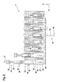
- FIG. 2 shows in a sectional view, the first embodiment in the FIG. 1 and the second embodiment in the FIG. 2 shown.
- Each of these figures shows in a series representation with joined sub-figures individual phases in the assembly of a first connector with a female contact and a subsequent insertion of a plug contact in the socket contact for closing the electrical connector.
- An electrical connector 11, according to the FIGS. 1 . 2 comprises a first connector 12, the socket contacts 13 and a second connector 14, the plug contacts 16 includes, which are insertable along a plug-in direction 17 in the associated socket contact 13.
- a contact carrier 18 of the first connector 12 11 arranged in rows receiving chambers 19 are arranged for the socket contacts 13 corresponding to the number of poles of the plug-in device.
- the socket contact 13 has for connection of an electrical conductor 21 a connecting portion 22, an adjoining locking portion 23 for fixing the position of the BuchungsWallets 13 in the receiving chamber 19 and a subsequent contact portion 24 for contacting with an associated male contact 16.
- the locking portion 23 occupies a reduced cross-sectional area with respect to the terminal portion 22 and the contact portion 24.
- FIG. 1 is in a first embodiment in a series representation with joined sub-figures, the assembly of a receiving chamber 19 by a socket contact 13 in the sequence of movement in a direction of insertion 17 opposing joining direction and the supply of one of the plug contacts 16 in the insertion direction 17 gradually shown progressively.
- the main body 26 has already passed through the feed opening 27 and is located for the most part in a sealing section 28 of the receiving chamber 19.
- An exposed end face 29 of the main body is already located in a centering funnel 31 adjacent to the sealing section 28 the preceding part of the figure uncovered and referred to here.
- the main body 26 is completely immersed in a bearing section 32, following the centering funnel 31, of the receiving chamber 19.
- the bearing portion 32 terminates at the end on a wall 33 which is pierced by an insertion opening 34, which widens in a funnel shape against the insertion direction 17.
- a laterally in the bearing portion 32 fixedly arranged spring-back locking arm 36 is biased by the base body 26 from its rest position, corresponding to the first two sub-figures, biased.
- wedge-shaped expansion element 37 is mounted on the wall. This is axially, in alignment with the plug-in direction 17, broken for a described in the following course passage of a plug-in contact 16.
- the spreader element 37 has penetrated into the contact section 24 so far that it can be rebated between two Contact blades 38 has arrived and this spread apart. Further, the latch arm 36 has returned to its rest position and blocked with a lying behind the main body 26 locking lug 39 a possible pushing out of the socket contact 13 from the receiving chamber 19th
- the feed movement of the socket contact 13 is closed in the receiving chamber 19 by a regurgitation of the end face 29 on the wall 33.
- a plug-in contact 34 directed towards the insertion opening 16 is fed to the socket contact 13 in the receiving chamber 19.
- the expansion element 37 reaches a region in which the distance of the contact blades 38 widens in a funnel shape, so that the influence of the expansion element 37 ends on the contact blades 38.
- the previously held contact blades 38 snap back and the contact between the contact blades 38 of the socket contact 13 and the plug contact 16 receives the desired high contact normal force.
- FIG. 2 is in a second embodiment in a series representation with joined sub-figures, the placement of a receiving chamber 19 by a female contact 13 in the movement in the joining direction 17 opposing joining direction and the supply of a plug-in contact 16 in the insertion direction 17 shown gradually progressing.
- the bar 43 detects a distance from an outer side of the wall 33 in the pre-locking position of the spreader 37 bottom plate 44 on which the spreader 37 is mounted perpendicular protruding and leads this bottom plate 44 to an end position when attacking the outside of the wall 33 with.
- the locking arm 36 secures with a locking lug 39 in this motion sequence here, as in the first embodiment, a pushing out of the contact portion 24 of the socket contact 13 against the joining direction of the bearing portion 32nd
Landscapes
- Connector Housings Or Holding Contact Members (AREA)
- Details Of Connecting Devices For Male And Female Coupling (AREA)
- Coupling Device And Connection With Printed Circuit (AREA)
Applications Claiming Priority (1)
| Application Number | Priority Date | Filing Date | Title |
|---|---|---|---|
| DE102008002592A DE102008002592A1 (de) | 2008-06-24 | 2008-06-24 | Elektrische Steckvorrichtung |
Publications (2)
| Publication Number | Publication Date |
|---|---|
| EP2139076A1 true EP2139076A1 (fr) | 2009-12-30 |
| EP2139076B1 EP2139076B1 (fr) | 2011-10-05 |
Family
ID=40909967
Family Applications (1)
| Application Number | Title | Priority Date | Filing Date |
|---|---|---|---|
| EP09100256A Not-in-force EP2139076B1 (fr) | 2008-06-24 | 2009-04-29 | Dispositif de raccordement électrique |
Country Status (3)
| Country | Link |
|---|---|
| EP (1) | EP2139076B1 (fr) |
| AT (1) | ATE527725T1 (fr) |
| DE (1) | DE102008002592A1 (fr) |
Families Citing this family (2)
| Publication number | Priority date | Publication date | Assignee | Title |
|---|---|---|---|---|
| DE202017002766U1 (de) | 2017-05-24 | 2017-06-16 | Berthold W. Seemann | Vorrichtung zur Abschreckung von Maulwürfen mittels Schall |
| DE202018001188U1 (de) | 2018-03-06 | 2018-03-23 | Berthold W. Seemann | Vibrator zur Vergrämung von Maulwürfen |
Citations (6)
| Publication number | Priority date | Publication date | Assignee | Title |
|---|---|---|---|---|
| EP0273999B1 (fr) | 1987-01-05 | 1993-09-29 | The Whitaker Corporation | Arrangement d'un connecteur à levier à crémaillère |
| EP0658952A1 (fr) * | 1993-12-15 | 1995-06-21 | Connecteurs Cinch | Organe femelle de contact électrique et élément de boîtier de connecteur électrique destiné à recevoir un tel organe |
| DE102005043417A1 (de) * | 2005-09-13 | 2007-03-15 | Robert Bosch Gmbh | Steckverbinder, Buchsenkontakt und Verriegelungselement für den Steckverbinder zur Herstellung einer elektrischen Steckverbindung |
| DE102005043158A1 (de) * | 2005-09-12 | 2007-03-15 | Robert Bosch Gmbh | Buchsenkontakt mit eigenständigem Primärverrastungsteil |
| EP1764875A1 (fr) * | 2005-09-14 | 2007-03-21 | Robert Bosch Gmbh | Connecteur électrique avec des contacts précontrainte |
| FR2896628A1 (fr) * | 2006-01-23 | 2007-07-27 | Tyco Electronics Amp Kk | Connecteur electrique de type flottant |
-
2008
- 2008-06-24 DE DE102008002592A patent/DE102008002592A1/de not_active Withdrawn
-
2009
- 2009-04-29 AT AT09100256T patent/ATE527725T1/de active
- 2009-04-29 EP EP09100256A patent/EP2139076B1/fr not_active Not-in-force
Patent Citations (6)
| Publication number | Priority date | Publication date | Assignee | Title |
|---|---|---|---|---|
| EP0273999B1 (fr) | 1987-01-05 | 1993-09-29 | The Whitaker Corporation | Arrangement d'un connecteur à levier à crémaillère |
| EP0658952A1 (fr) * | 1993-12-15 | 1995-06-21 | Connecteurs Cinch | Organe femelle de contact électrique et élément de boîtier de connecteur électrique destiné à recevoir un tel organe |
| DE102005043158A1 (de) * | 2005-09-12 | 2007-03-15 | Robert Bosch Gmbh | Buchsenkontakt mit eigenständigem Primärverrastungsteil |
| DE102005043417A1 (de) * | 2005-09-13 | 2007-03-15 | Robert Bosch Gmbh | Steckverbinder, Buchsenkontakt und Verriegelungselement für den Steckverbinder zur Herstellung einer elektrischen Steckverbindung |
| EP1764875A1 (fr) * | 2005-09-14 | 2007-03-21 | Robert Bosch Gmbh | Connecteur électrique avec des contacts précontrainte |
| FR2896628A1 (fr) * | 2006-01-23 | 2007-07-27 | Tyco Electronics Amp Kk | Connecteur electrique de type flottant |
Also Published As
| Publication number | Publication date |
|---|---|
| ATE527725T1 (de) | 2011-10-15 |
| EP2139076B1 (fr) | 2011-10-05 |
| DE102008002592A1 (de) | 2009-12-31 |
Similar Documents
| Publication | Publication Date | Title |
|---|---|---|
| DE68909838T2 (de) | Doppeleinfügungsstruktur für Anschlussklemmen in Steckverbindern. | |
| DE60121656T2 (de) | Ständer und automatische Maschine zur Schneidklemmverbindung | |
| DE69405782T2 (de) | Verbinder | |
| DE69819057T2 (de) | Verbinder | |
| EP3329558B1 (fr) | Connecteur électrique | |
| EP0554810A2 (fr) | Connecteur électrique | |
| DE69415951T2 (de) | Verbinderanordnung | |
| DE3705739C2 (de) | Elektrische Verbinderanordnung | |
| DE29716767U1 (de) | Flachsteckhülse zum elektrischen Verbinden eines eine abisolierte Litze aufweisenden Kabels o.dgl. mit einem Flachstecker | |
| DE102006030784B4 (de) | Steckverbinder mit einer Sekundärverriegelung | |
| EP3375048A1 (fr) | Contact à enficher | |
| DE69118145T2 (de) | Halterungsaufbau für metallische Anschlussklemme | |
| DE69411772T2 (de) | Elektrischer Verbinder mit Kontaktrückhaltemitteln | |
| DE102023105968A1 (de) | Geschirmter PushPull-Stecker mit Schirmfeder | |
| EP3288121A1 (fr) | Connecteur enfichable entièrement hermétique doté des forces de rétention améliorées | |
| EP1764875B1 (fr) | Connecteur électrique avec des lamelles de contact précontraintes | |
| EP2139076B1 (fr) | Dispositif de raccordement électrique | |
| DE102012106741B4 (de) | Kontaktelement | |
| DE2842892A1 (de) | Elektrischer verbinder | |
| DE19949386C2 (de) | Geräte-Anschlusskasten mit Schneidtechnik | |
| DE10111473B4 (de) | Verbinder | |
| EP2026416B1 (fr) | Dispositif de réception de câble et système de contact | |
| DE102013110512B4 (de) | Steckverbinder mit Primär- und Sekundärverriegelung | |
| DE102008042610A1 (de) | Elektrische Steckvorrichtung | |
| DE69608557T2 (de) | Zeitliche anschlussrückhaltung |
Legal Events
| Date | Code | Title | Description |
|---|---|---|---|
| PUAI | Public reference made under article 153(3) epc to a published international application that has entered the european phase |
Free format text: ORIGINAL CODE: 0009012 |
|
| AK | Designated contracting states |
Kind code of ref document: A1 Designated state(s): AT BE BG CH CY CZ DE DK EE ES FI FR GB GR HR HU IE IS IT LI LT LU LV MC MK MT NL NO PL PT RO SE SI SK TR |
|
| 17P | Request for examination filed |
Effective date: 20100630 |
|
| 17Q | First examination report despatched |
Effective date: 20100716 |
|
| GRAP | Despatch of communication of intention to grant a patent |
Free format text: ORIGINAL CODE: EPIDOSNIGR1 |
|
| GRAS | Grant fee paid |
Free format text: ORIGINAL CODE: EPIDOSNIGR3 |
|
| GRAA | (expected) grant |
Free format text: ORIGINAL CODE: 0009210 |
|
| AK | Designated contracting states |
Kind code of ref document: B1 Designated state(s): AT BE BG CH CY CZ DE DK EE ES FI FR GB GR HR HU IE IS IT LI LT LU LV MC MK MT NL NO PL PT RO SE SI SK TR |
|
| REG | Reference to a national code |
Ref country code: GB Ref legal event code: FG4D Free format text: NOT ENGLISH |
|
| REG | Reference to a national code |
Ref country code: CH Ref legal event code: EP |
|
| REG | Reference to a national code |
Ref country code: IE Ref legal event code: FG4D |
|
| REG | Reference to a national code |
Ref country code: DE Ref legal event code: R096 Ref document number: 502009001503 Country of ref document: DE Effective date: 20111201 |
|
| REG | Reference to a national code |
Ref country code: NL Ref legal event code: VDEP Effective date: 20111005 |
|
| PG25 | Lapsed in a contracting state [announced via postgrant information from national office to epo] |
Ref country code: SI Free format text: LAPSE BECAUSE OF FAILURE TO SUBMIT A TRANSLATION OF THE DESCRIPTION OR TO PAY THE FEE WITHIN THE PRESCRIBED TIME-LIMIT Effective date: 20111005 |
|
| LTIE | Lt: invalidation of european patent or patent extension |
Effective date: 20111005 |
|
| PG25 | Lapsed in a contracting state [announced via postgrant information from national office to epo] |
Ref country code: IS Free format text: LAPSE BECAUSE OF FAILURE TO SUBMIT A TRANSLATION OF THE DESCRIPTION OR TO PAY THE FEE WITHIN THE PRESCRIBED TIME-LIMIT Effective date: 20120205 Ref country code: LT Free format text: LAPSE BECAUSE OF FAILURE TO SUBMIT A TRANSLATION OF THE DESCRIPTION OR TO PAY THE FEE WITHIN THE PRESCRIBED TIME-LIMIT Effective date: 20111005 Ref country code: NO Free format text: LAPSE BECAUSE OF FAILURE TO SUBMIT A TRANSLATION OF THE DESCRIPTION OR TO PAY THE FEE WITHIN THE PRESCRIBED TIME-LIMIT Effective date: 20120105 |
|
| REG | Reference to a national code |
Ref country code: IE Ref legal event code: FD4D |
|
| PG25 | Lapsed in a contracting state [announced via postgrant information from national office to epo] |
Ref country code: LV Free format text: LAPSE BECAUSE OF FAILURE TO SUBMIT A TRANSLATION OF THE DESCRIPTION OR TO PAY THE FEE WITHIN THE PRESCRIBED TIME-LIMIT Effective date: 20111005 Ref country code: NL Free format text: LAPSE BECAUSE OF FAILURE TO SUBMIT A TRANSLATION OF THE DESCRIPTION OR TO PAY THE FEE WITHIN THE PRESCRIBED TIME-LIMIT Effective date: 20111005 Ref country code: GR Free format text: LAPSE BECAUSE OF FAILURE TO SUBMIT A TRANSLATION OF THE DESCRIPTION OR TO PAY THE FEE WITHIN THE PRESCRIBED TIME-LIMIT Effective date: 20120106 Ref country code: PT Free format text: LAPSE BECAUSE OF FAILURE TO SUBMIT A TRANSLATION OF THE DESCRIPTION OR TO PAY THE FEE WITHIN THE PRESCRIBED TIME-LIMIT Effective date: 20120206 Ref country code: HR Free format text: LAPSE BECAUSE OF FAILURE TO SUBMIT A TRANSLATION OF THE DESCRIPTION OR TO PAY THE FEE WITHIN THE PRESCRIBED TIME-LIMIT Effective date: 20111005 Ref country code: SE Free format text: LAPSE BECAUSE OF FAILURE TO SUBMIT A TRANSLATION OF THE DESCRIPTION OR TO PAY THE FEE WITHIN THE PRESCRIBED TIME-LIMIT Effective date: 20111005 |
|
| PG25 | Lapsed in a contracting state [announced via postgrant information from national office to epo] |
Ref country code: CY Free format text: LAPSE BECAUSE OF FAILURE TO SUBMIT A TRANSLATION OF THE DESCRIPTION OR TO PAY THE FEE WITHIN THE PRESCRIBED TIME-LIMIT Effective date: 20111005 |
|
| PG25 | Lapsed in a contracting state [announced via postgrant information from national office to epo] |
Ref country code: CZ Free format text: LAPSE BECAUSE OF FAILURE TO SUBMIT A TRANSLATION OF THE DESCRIPTION OR TO PAY THE FEE WITHIN THE PRESCRIBED TIME-LIMIT Effective date: 20111005 Ref country code: IE Free format text: LAPSE BECAUSE OF FAILURE TO SUBMIT A TRANSLATION OF THE DESCRIPTION OR TO PAY THE FEE WITHIN THE PRESCRIBED TIME-LIMIT Effective date: 20111005 Ref country code: SK Free format text: LAPSE BECAUSE OF FAILURE TO SUBMIT A TRANSLATION OF THE DESCRIPTION OR TO PAY THE FEE WITHIN THE PRESCRIBED TIME-LIMIT Effective date: 20111005 Ref country code: BG Free format text: LAPSE BECAUSE OF FAILURE TO SUBMIT A TRANSLATION OF THE DESCRIPTION OR TO PAY THE FEE WITHIN THE PRESCRIBED TIME-LIMIT Effective date: 20120105 Ref country code: EE Free format text: LAPSE BECAUSE OF FAILURE TO SUBMIT A TRANSLATION OF THE DESCRIPTION OR TO PAY THE FEE WITHIN THE PRESCRIBED TIME-LIMIT Effective date: 20111005 Ref country code: DK Free format text: LAPSE BECAUSE OF FAILURE TO SUBMIT A TRANSLATION OF THE DESCRIPTION OR TO PAY THE FEE WITHIN THE PRESCRIBED TIME-LIMIT Effective date: 20111005 |
|
| PLBE | No opposition filed within time limit |
Free format text: ORIGINAL CODE: 0009261 |
|
| STAA | Information on the status of an ep patent application or granted ep patent |
Free format text: STATUS: NO OPPOSITION FILED WITHIN TIME LIMIT |
|
| PG25 | Lapsed in a contracting state [announced via postgrant information from national office to epo] |
Ref country code: RO Free format text: LAPSE BECAUSE OF FAILURE TO SUBMIT A TRANSLATION OF THE DESCRIPTION OR TO PAY THE FEE WITHIN THE PRESCRIBED TIME-LIMIT Effective date: 20111005 Ref country code: PL Free format text: LAPSE BECAUSE OF FAILURE TO SUBMIT A TRANSLATION OF THE DESCRIPTION OR TO PAY THE FEE WITHIN THE PRESCRIBED TIME-LIMIT Effective date: 20111005 |
|
| 26N | No opposition filed |
Effective date: 20120706 |
|
| BERE | Be: lapsed |
Owner name: ROBERT BOSCH G.M.B.H. Effective date: 20120430 |
|
| REG | Reference to a national code |
Ref country code: DE Ref legal event code: R097 Ref document number: 502009001503 Country of ref document: DE Effective date: 20120706 |
|
| PG25 | Lapsed in a contracting state [announced via postgrant information from national office to epo] |
Ref country code: MC Free format text: LAPSE BECAUSE OF NON-PAYMENT OF DUE FEES Effective date: 20120430 |
|
| PG25 | Lapsed in a contracting state [announced via postgrant information from national office to epo] |
Ref country code: BE Free format text: LAPSE BECAUSE OF NON-PAYMENT OF DUE FEES Effective date: 20120430 |
|
| PG25 | Lapsed in a contracting state [announced via postgrant information from national office to epo] |
Ref country code: MK Free format text: LAPSE BECAUSE OF FAILURE TO SUBMIT A TRANSLATION OF THE DESCRIPTION OR TO PAY THE FEE WITHIN THE PRESCRIBED TIME-LIMIT Effective date: 20111005 |
|
| PG25 | Lapsed in a contracting state [announced via postgrant information from national office to epo] |
Ref country code: ES Free format text: LAPSE BECAUSE OF FAILURE TO SUBMIT A TRANSLATION OF THE DESCRIPTION OR TO PAY THE FEE WITHIN THE PRESCRIBED TIME-LIMIT Effective date: 20120116 |
|
| PG25 | Lapsed in a contracting state [announced via postgrant information from national office to epo] |
Ref country code: FI Free format text: LAPSE BECAUSE OF FAILURE TO SUBMIT A TRANSLATION OF THE DESCRIPTION OR TO PAY THE FEE WITHIN THE PRESCRIBED TIME-LIMIT Effective date: 20111005 |
|
| PG25 | Lapsed in a contracting state [announced via postgrant information from national office to epo] |
Ref country code: MT Free format text: LAPSE BECAUSE OF FAILURE TO SUBMIT A TRANSLATION OF THE DESCRIPTION OR TO PAY THE FEE WITHIN THE PRESCRIBED TIME-LIMIT Effective date: 20111005 |
|
| REG | Reference to a national code |
Ref country code: CH Ref legal event code: PL |
|
| GBPC | Gb: european patent ceased through non-payment of renewal fee |
Effective date: 20130429 |
|
| PG25 | Lapsed in a contracting state [announced via postgrant information from national office to epo] |
Ref country code: GB Free format text: LAPSE BECAUSE OF NON-PAYMENT OF DUE FEES Effective date: 20130429 Ref country code: CH Free format text: LAPSE BECAUSE OF NON-PAYMENT OF DUE FEES Effective date: 20130430 Ref country code: LI Free format text: LAPSE BECAUSE OF NON-PAYMENT OF DUE FEES Effective date: 20130430 |
|
| PG25 | Lapsed in a contracting state [announced via postgrant information from national office to epo] |
Ref country code: TR Free format text: LAPSE BECAUSE OF FAILURE TO SUBMIT A TRANSLATION OF THE DESCRIPTION OR TO PAY THE FEE WITHIN THE PRESCRIBED TIME-LIMIT Effective date: 20111005 |
|
| PG25 | Lapsed in a contracting state [announced via postgrant information from national office to epo] |
Ref country code: LU Free format text: LAPSE BECAUSE OF NON-PAYMENT OF DUE FEES Effective date: 20120429 |
|
| PG25 | Lapsed in a contracting state [announced via postgrant information from national office to epo] |
Ref country code: HU Free format text: LAPSE BECAUSE OF FAILURE TO SUBMIT A TRANSLATION OF THE DESCRIPTION OR TO PAY THE FEE WITHIN THE PRESCRIBED TIME-LIMIT Effective date: 20090429 |
|
| REG | Reference to a national code |
Ref country code: AT Ref legal event code: MM01 Ref document number: 527725 Country of ref document: AT Kind code of ref document: T Effective date: 20140429 |
|
| PG25 | Lapsed in a contracting state [announced via postgrant information from national office to epo] |
Ref country code: AT Free format text: LAPSE BECAUSE OF NON-PAYMENT OF DUE FEES Effective date: 20140429 |
|
| REG | Reference to a national code |
Ref country code: FR Ref legal event code: PLFP Year of fee payment: 8 |
|
| REG | Reference to a national code |
Ref country code: FR Ref legal event code: PLFP Year of fee payment: 9 |
|
| REG | Reference to a national code |
Ref country code: FR Ref legal event code: PLFP Year of fee payment: 10 |
|
| PGFP | Annual fee paid to national office [announced via postgrant information from national office to epo] |
Ref country code: FR Payment date: 20200421 Year of fee payment: 12 |
|
| PGFP | Annual fee paid to national office [announced via postgrant information from national office to epo] |
Ref country code: IT Payment date: 20200423 Year of fee payment: 12 |
|
| PG25 | Lapsed in a contracting state [announced via postgrant information from national office to epo] |
Ref country code: FR Free format text: LAPSE BECAUSE OF NON-PAYMENT OF DUE FEES Effective date: 20210430 |
|
| PG25 | Lapsed in a contracting state [announced via postgrant information from national office to epo] |
Ref country code: IT Free format text: LAPSE BECAUSE OF NON-PAYMENT OF DUE FEES Effective date: 20200429 |
|
| PGFP | Annual fee paid to national office [announced via postgrant information from national office to epo] |
Ref country code: DE Payment date: 20230627 Year of fee payment: 15 |
|
| REG | Reference to a national code |
Ref country code: DE Ref legal event code: R119 Ref document number: 502009001503 Country of ref document: DE |
|
| PG25 | Lapsed in a contracting state [announced via postgrant information from national office to epo] |
Ref country code: DE Free format text: LAPSE BECAUSE OF NON-PAYMENT OF DUE FEES Effective date: 20241105 |
|
| PG25 | Lapsed in a contracting state [announced via postgrant information from national office to epo] |
Ref country code: DE Free format text: LAPSE BECAUSE OF NON-PAYMENT OF DUE FEES Effective date: 20241105 |
|
| PG25 | Lapsed in a contracting state [announced via postgrant information from national office to epo] |
Ref country code: IT Free format text: LAPSE BECAUSE OF NON-PAYMENT OF DUE FEES Effective date: 20210429 |