EP2140287B1 - Système d'assistance au conducteur et procédé pour améliorer la vraisemblance liée à des d'objets - Google Patents
Système d'assistance au conducteur et procédé pour améliorer la vraisemblance liée à des d'objets Download PDFInfo
- Publication number
- EP2140287B1 EP2140287B1 EP08717325A EP08717325A EP2140287B1 EP 2140287 B1 EP2140287 B1 EP 2140287B1 EP 08717325 A EP08717325 A EP 08717325A EP 08717325 A EP08717325 A EP 08717325A EP 2140287 B1 EP2140287 B1 EP 2140287B1
- Authority
- EP
- European Patent Office
- Prior art keywords
- objects
- systems
- vehicle
- collision
- radar
- Prior art date
- Legal status (The legal status is an assumption and is not a legal conclusion. Google has not performed a legal analysis and makes no representation as to the accuracy of the status listed.)
- Active
Links
Images


Classifications
-
- G—PHYSICS
- G01—MEASURING; TESTING
- G01S—RADIO DIRECTION-FINDING; RADIO NAVIGATION; DETERMINING DISTANCE OR VELOCITY BY USE OF RADIO WAVES; LOCATING OR PRESENCE-DETECTING BY USE OF THE REFLECTION OR RERADIATION OF RADIO WAVES; ANALOGOUS ARRANGEMENTS USING OTHER WAVES
- G01S13/00—Systems using the reflection or reradiation of radio waves, e.g. radar systems; Analogous systems using reflection or reradiation of waves whose nature or wavelength is irrelevant or unspecified
- G01S13/88—Radar or analogous systems specially adapted for specific applications
- G01S13/93—Radar or analogous systems specially adapted for specific applications for anti-collision purposes
- G01S13/931—Radar or analogous systems specially adapted for specific applications for anti-collision purposes of land vehicles
-
- G—PHYSICS
- G01—MEASURING; TESTING
- G01S—RADIO DIRECTION-FINDING; RADIO NAVIGATION; DETERMINING DISTANCE OR VELOCITY BY USE OF RADIO WAVES; LOCATING OR PRESENCE-DETECTING BY USE OF THE REFLECTION OR RERADIATION OF RADIO WAVES; ANALOGOUS ARRANGEMENTS USING OTHER WAVES
- G01S11/00—Systems for determining distance or velocity not using reflection or reradiation
- G01S11/12—Systems for determining distance or velocity not using reflection or reradiation using electromagnetic waves other than radio waves
-
- G—PHYSICS
- G01—MEASURING; TESTING
- G01S—RADIO DIRECTION-FINDING; RADIO NAVIGATION; DETERMINING DISTANCE OR VELOCITY BY USE OF RADIO WAVES; LOCATING OR PRESENCE-DETECTING BY USE OF THE REFLECTION OR RERADIATION OF RADIO WAVES; ANALOGOUS ARRANGEMENTS USING OTHER WAVES
- G01S13/00—Systems using the reflection or reradiation of radio waves, e.g. radar systems; Analogous systems using reflection or reradiation of waves whose nature or wavelength is irrelevant or unspecified
- G01S13/86—Combinations of radar systems with non-radar systems, e.g. sonar, direction finder
- G01S13/867—Combination of radar systems with cameras
-
- B—PERFORMING OPERATIONS; TRANSPORTING
- B60—VEHICLES IN GENERAL
- B60W—CONJOINT CONTROL OF VEHICLE SUB-UNITS OF DIFFERENT TYPE OR DIFFERENT FUNCTION; CONTROL SYSTEMS SPECIALLY ADAPTED FOR HYBRID VEHICLES; ROAD VEHICLE DRIVE CONTROL SYSTEMS FOR PURPOSES NOT RELATED TO THE CONTROL OF A PARTICULAR SUB-UNIT
- B60W2420/00—Indexing codes relating to the type of sensors based on the principle of their operation
- B60W2420/40—Photo, light or radio wave sensitive means, e.g. infrared sensors
- B60W2420/408—Radar; Laser, e.g. lidar
-
- G—PHYSICS
- G01—MEASURING; TESTING
- G01S—RADIO DIRECTION-FINDING; RADIO NAVIGATION; DETERMINING DISTANCE OR VELOCITY BY USE OF RADIO WAVES; LOCATING OR PRESENCE-DETECTING BY USE OF THE REFLECTION OR RERADIATION OF RADIO WAVES; ANALOGOUS ARRANGEMENTS USING OTHER WAVES
- G01S13/00—Systems using the reflection or reradiation of radio waves, e.g. radar systems; Analogous systems using reflection or reradiation of waves whose nature or wavelength is irrelevant or unspecified
- G01S13/88—Radar or analogous systems specially adapted for specific applications
- G01S13/93—Radar or analogous systems specially adapted for specific applications for anti-collision purposes
- G01S13/931—Radar or analogous systems specially adapted for specific applications for anti-collision purposes of land vehicles
- G01S2013/9325—Radar or analogous systems specially adapted for specific applications for anti-collision purposes of land vehicles for inter-vehicle distance regulation, e.g. navigating in platoons
-
- G—PHYSICS
- G01—MEASURING; TESTING
- G01S—RADIO DIRECTION-FINDING; RADIO NAVIGATION; DETERMINING DISTANCE OR VELOCITY BY USE OF RADIO WAVES; LOCATING OR PRESENCE-DETECTING BY USE OF THE REFLECTION OR RERADIATION OF RADIO WAVES; ANALOGOUS ARRANGEMENTS USING OTHER WAVES
- G01S13/00—Systems using the reflection or reradiation of radio waves, e.g. radar systems; Analogous systems using reflection or reradiation of waves whose nature or wavelength is irrelevant or unspecified
- G01S13/88—Radar or analogous systems specially adapted for specific applications
- G01S13/93—Radar or analogous systems specially adapted for specific applications for anti-collision purposes
- G01S13/931—Radar or analogous systems specially adapted for specific applications for anti-collision purposes of land vehicles
- G01S2013/9327—Sensor installation details
- G01S2013/93271—Sensor installation details in the front of the vehicles
Definitions
- the invention relates to a method for object plausibility in driver assistance systems for motor vehicles, in which two measured variables are derived from location data of two independently operating object location systems of the vehicle for an object which is located by both locating systems, one for each location system, one and the same represent physical parameters, and in which then the two measured variables are checked for consistency.
- the invention also relates to a driver assistance system that is set up to carry out this method.
- driver assistance systems examples include, for example, so-called predictive safety systems (PSS) and automatic cruise control systems (ACC).
- PSS predictive safety systems
- ACC automatic cruise control systems
- at least one object location system for example a radar system or a video-based system, is provided for the surroundings of the vehicle equipped with the assistance system monitor and locate objects in the vicinity of the vehicle, in particular vehicles in front and other obstacles.
- the location data is used to "predictively" calculate whether a collision with an object will occur, and in the event of an acute collision hazard, a warning signal is output.
- this warning signal is converted into an acoustic signal intended to alert the driver to the danger.
- the warning signal immediately omits an automatic intervention in the longitudinal guidance of the vehicle, for example emergency braking, in order to avert the collision or at least mitigate its consequences.
- the reliability of the object location can be improved by providing two independently operating location systems so that some redundancy is achieved.
- DE 103 99 943 A1 describes a method that uses two independent locating systems, one of which provides data optimized for longitudinal value, while the other system provides lateral value or lateral extension-optimized data.
- An example of a longitudinally optimized system is a radar system that provides relatively accurate distance and distance measurements Relative speed of an object provides, but even if the radar sensor has a certain angular resolution, only inaccurate data for the azimuth angle and thus the lateral position of the object provides.
- the lateral extent of the object can also be very roughly determined with such a sensor
- a lateralwertoptimators system is a video-based system, so for example a video camera with associated image processing electronics.
- a system can provide relatively accurate data about the azimuth angle and the lateral extent of an object, but, especially in monocular systems, allows only an inaccurate determination or estimation of the object distance, and the relative velocity can only be determined indirectly by time derivative of the inaccurate distance data .
- the distance can only be roughly estimated from the height of the object in the video image relative to the height of the horizon line.
- the accuracy can be slightly improved by a roadway estimation.
- a binocular video system allows distance determination by triangulation, but also provides only relatively inaccurate values, especially at longer distances.
- the longitudinal-value-optimized system locates an object whose lateral position and extent can only be specified within relatively wide tolerance limits, it can be checked with the aid of the lateral-value-optimized system whether an object is located by this system that lies within the wide tolerance limits.
- the lateral value-optimized system will in turn be able to indicate the distance of the object only within relatively large error limits.
- WO 2005/098782 A1 describes a method by which the "time to collision" in a video-based system based on the change in the scale factor of a detected object from measuring cycle to measuring cycle can be calculated without the object distances must be known exactly at the respective measurement times.
- an object detection device for driver assistance systems in motor vehicles with at least two sensor systems that measure data about the location and / or state of motion of objects in the vicinity of the vehicle and whose detection ranges overlap each other, by an error detection device, the measured by the sensor systems data on checks their consistency and outputs an error signal upon detection of a contradiction.
- the object of the invention is to provide a method for object plausibility, which allows a more reliable plausibility of the objects located by both detection systems.
- This object is achieved in a method of the type mentioned in the present invention, that the parameter that is used by the two measured variables used for the consistency check is represented, the pre-calculated time until the collision of the vehicle with the object (ie the "time to collision") is.
- a measurement quantity for the "time to collision” is first calculated from the location data obtained with each individual object location system, and these two independently obtained values for the "time to collision” are then compared with each other for object plausibility. If these two values are sufficiently similar, it can be assumed with great certainty that both object locating systems have located the same object and correctly assessed the collision risk posed by this object, because it is extremely unlikely that both systems will provide the same "time to collision” if the two systems Positioning data of one of the two systems based on a measurement error or interpretation error.
- the method according to the invention avoids the uncertainties that result from the difficulty of correctly assigning the location data obtained for different objects by the two positioning systems.
- the invention is particularly advantageous if one of the two object location systems is an FMCW (Frequency Modulated Continuous Wave) radar, which is already being used today in many driver assistance systems as a radar object location system.
- FMCW Frequency Modulated Continuous Wave
- an FMCW radar by mixing the signal reflected from such an object and received back from the sensor with the signal transmitted by that sensor at the time of reception, an intermediate frequency signal indicative of the difference in frequency between the transmitted and received signals is generated. From this intermediate frequency signal, the "time to collision" can be determined. Obtained in this way by a very fast and less error-prone process one of the two variables that is needed for the consistency check.
- the other object location system is a video-based system
- a measure for the "time to collision” can be calculated, such as WO 2005/098782 is known. Overall, one obtains for the "time to collision" by very fast and secure algorithms two measures, which then only need to be checked for compliance.
- the invention also solves a problem known as the problem of "dummy objects".
- the intermediate frequency signal obtained by a FMCW radar in a single measurement operation for a single object is dependent both on the distance of that object and on the Doppler shift, and thus on the relative velocity of the object, thus providing neither distance nor relative velocity directly an exact measurement, but only a relationship between distance and relative velocity, which must apply to the object in question.
- FMCW radar modulates the frequency of the transmitted radar signal with at least two different frequency ramps. For a given object, one then holds for each of the two frequency ramps a different relationship between distance and relative velocity, and the "right" values for the distance and the relative velocity are those values at which both relations are satisfied.
- the "time to collision" which is obtained independently with the aid of the second locating system, can now be used as an additional criterion in order to distinguish real objects and apparent objects.
- the "time to collision” represents for each object a particular relationship between distance and relative velocity, and only for real objects will this relationship be consistent with the relationships obtained from the intermediate frequency signals on two frequency ramps. In this way, the invention makes it possible to reliably distinguish between real objects and fake objects.
- Fig. 1 is a driver assistance system for a motor vehicle, in this example a combination of a distance control system (ACC) and a predictive safety system (PSS), shown as a block diagram.
- the system comprises two independently working ones Object location systems for detecting the apron of the vehicle equipped with the driver assistance system.
- a first object location system is formed by a radar sensor 10, in the example shown an FMCW radar.
- the received radar signals are preprocessed in an evaluation stage 12, so that one obtains location data 14 for one or more located objects.
- Each object is described by a set of location data that includes the distance, the relative speed, and the azimuth angle of the object.
- the radar measurements are made cyclically with a period of the order of 100 ms, so that the location data 14 is updated at short intervals.
- a monocular video system with a front-mounted in the vehicle, front-facing video camera 16 and an associated image processing module 18 is provided.
- the image processing module 18 evaluates the periodically captured by the video camera 16 digital images and recognizes in these images predefined object classes, such as vehicles, people, crash barriers, lane markings and the like.
- object classes such as vehicles, people, crash barriers, lane markings and the like.
- the image processing module 18 provides location data 20, which include the distance, the lateral position (azimuth angle) and the lateral extent of the object (eg vehicle width) for each located object.
- the location data 14 and 20 obtained with the various object location systems are independent from each other, but describe in part identical or equivalent physical quantities, such as the object distance and the lateral position of the object, which can be calculated from the distance and azimuth angle measured by the radar sensor.
- the core of the driver assistance system is an electronic data processing system 22, which is formed by a computer and associated software and evaluates the location data 14, 20 supplied by the two object location systems.
- a tracking module 24 serves to match the position data 14 delivered by the radar sensor 10 in successive measuring cycles in a known manner so as to identify the objects located in one cycle with the objects located in the previous cycle and to track the movements of the objects.
- a ttc module 26 calculates, based on the data of the tracking module 24, a "time to collision" based on the radar data, which is hereby designated T r and indicates for each located object the pre-calculated time which elapses until the collision of the own vehicle with the vehicle In the meantime, it would still be necessary for the relevant object to be assumed, provided that it is assumed that the dynamic data of the own vehicle and the object do not change in the meantime.
- this time to collision is calculated primarily for objects located within the expected driving range of one's own vehicle, but this time to collision can also be calculated for off-track objects by relying on a one-dimensional Contemplation limited, in which only the coordinates in the longitudinal direction of the vehicle are taken into account.
- the location data 20 of the video system is periodically updated, with a period that does not necessarily have to be identical to the measurement period of the radar sensor 10.
- Another tracking module 28 therefore serves to track the located video objects based on the periodically arriving location data 20.
- Analogous to the ttc module 26, another ttc module 30 is provided to calculate a time to collision T v for each located video object. This calculation is also carried out in the example shown on the basis of the data of the associated tracking module 28, but can optionally or additionally also be performed on the basis of the data of the image processing module 18. It is also conceivable that the function of the ttc module 30 is integrated into the image processing module 18 or vice versa, the image processing module 18 is integrated into the data processing system 22.
- a comparison module 32 the measured variables T r and T v calculated by the two ttc modules 26, 30, which are based on location data collected independently of one another, are compared with one another. If these two measured variables agree within certain accuracy limits, then it can be assumed that the relevant objects, which are represented on the one hand by the location data 14 and on the other hand by the location data 20, correspond to one and the same physical object.
- This information is used in a plausibility check module 34 to validate the tracked by the tracking module 24 radar objects, ie, if for a given object a coincidence of the two measures for the time to collision is determined, this means that the object location was confirmed by means of the radar sensor 10 by the object location using the video system, and thus one obtains increased certainty that it is the object in question to a real object.
- This plausibility check can also refer to the object classification.
- a real obstacle such as a stationary vehicle
- the video system will recognize only the predefined object classes from the outset and will therefore ignore manhole covers and the like.
- the information provided by the comparison module 32 can therefore also serve to confirm that the stationary object located by the radar sensor is a real obstacle.
- a certain refinement of the location data supplied by the radar sensor can also take place.
- the lateral extent of an object can only be estimated approximately on the basis of the strength of the radar echo and / or the distribution of the azimuth angles.
- a very large object, such as a preceding truck can also produce multiple radar echoes that result from different reflex points on the truck.
- the comparison module 32 reports that the video system has located only a single object with this time to collision, then it is clear that the two radar echoes originate from the same object , In this way, the information about the lateral extent of the object can be specified in the plausibility check module 34.
- the tracking module 28 for the video objects is also followed by a plausibility check module 36, with which the video objects are plausibilized on analogous masters if the two measured quantities T r and T v coincide.
- the comparison module 32 supplies at the same time a parameter TTC, which corresponds to the two matching measured variables in accordance with the two measured variables T r and T v .
- This parameter TTC is transmitted by a TTC fusion module 38 as a "confirmed" time to collision to a PSS module 40, ie the part of the driver assistance system that is responsible for the predictive safety function.
- the parameter TTC should only be transferred for those objects that were located by both object location systems within the expected driving range of the own vehicle. If the ttc modules 26 and 30 also calculate measured variables T r and T v for objects that lie outside the estimated driving course, a flag indicating whether the object can be transmitted for this purpose via the comparison module 32 together with the measured variable inside or outside the driving corridor.
- a data fusion module 42 the location data of the objects that are plausibilized and possibly specified in the plausibility modules 34 and 36 are fused together, i. h., it is now formed for each located object, a uniform data set indicating the location, the relative speed, the lateral position and the lateral extent of the object.
- the respective measurement accuracy of the object location systems is taken into account. For example, the value for the object distance will be largely determined by the data of the radar sensor 10, while in the fusion of the data for this lateral position and the lateral extent of the object the data of the video system will be given a higher weight.
- a new value for the parameter TTC ie the time to collision
- this parameter TCC will be the quotient of the distance and the relative velocity calculated in the data fusion module 42.
- this more accurate value is then fused with the preliminary value provided by the comparison module 32 or replaces the tentative value so that the PSS module 40 can operate with a more accurate time to collision estimate.
- the measured variables are calculated T r and T v only a first approximation, in this embodiment for the purpose of pplausibilmaschine, that is, assuming constant Speeds. While this provides only relatively inaccurate estimates for the actual time to collision, it simplifies the calculations and provides a method for object validation that is no less sensitive than using higher approximations.
- the lateral position and the lateral extent of the object are determined more accurately, these data can be transferred to the PSS module, so that it can then be decided again in this module based on the more accurate data, whether there is a possibility, the object in which case some or all of the actions foreseen by the PSS module may be suspended.
- An expedient embodiment may consist in the PSS module 40 issuing a warning to the driver as soon as a parameter TTC supplied by the comparison module 32 is below the relevant threshold value, but that automatic intervention in the longitudinal guidance of the vehicle takes place only on the basis of the more accurate data of the data fusion module 42.
- the more accurate location data of the objects calculated by the data fusion module 42, in particular for the immediately preceding vehicle, are also transferred to an ACC module 44, which automatically regulates the distance to the vehicle in front.
- the ACC module 44 may also receive the location data directly from the plausibility module 34, as in FIG Fig. 1 is indicated by a dashed arrow.
- the video system is used only for object plausibility, while the distance control otherwise takes place solely on the basis of the data from the radar sensor 10.
- Fig. 2 is a vehicle 46 compatible with the driver assistance system Fig. 1 equipped, shown in a side view.
- a preceding vehicle 48 is shown. For this preceding vehicle 48, the radar sensor 10 measures the distance d r .
- the video system measures for the same vehicle 48 the distance d, which will generally be slightly larger because the video camera 16 will be axially offset from the radar sensor 10 in the vehicle 46.
- the distance between the radar sensor 10 and the video sensor 16 in the longitudinal direction of the vehicle 46 is in Fig. 2 denoted by d rv . This distance must be taken into account in the data fusion and also in the calculation of the measured variables T r and T v for the time to collision.
- FIGS. 3 to 5 Let us first explain how the measured variable T v for the time to collision is calculated on the basis of the data of the video system.
- Fig. 3 shows an image 50 taken at a certain time with the video camera 16. In this picture, the silhouette of the preceding vehicle 48 can be seen. Digital image processing extracts an apparent width s 1 of the preceding vehicle 48 from the image.
- FIG. 12 shows an image 52 taken by the video camera 16 at a later time, such as a video measurement cycle later. It is assumed here that the relative speed of the vehicle 48 is negative, that is, the distance between the vehicles 48 and 46 decreases. In the image 52, therefore, the silhouette of the vehicle 48 appears enlarged by a certain scaling factor, since the vehicle has now come closer. The apparent width of the vehicle 48 is s 2 in this case.
- Fig. 5 For example, the situation at the time the images 50 and 52 were taken is shown in a schematic plan view.
- the position of the vehicle 48 when the image 50 is captured is designated 48a, and the position of the image 52 taken at 48b.
- ⁇ 1 B / d 1
- the time to collision can be calculated directly from the change in the scaling of the images 50, 52, without the relevant vehicle distances must be known.
- the measured variable T r for the time to collision can be calculated simply by dividing the measured distance by the measured relative speed.
- the conventional method for determining distance and relative speed is briefly outlined below.
- the frequency of the radar signal sent from the radar sensor 10 is ramp-modulated, as in FIG Fig. 6 is shown.
- the frequency increases linearly on a ramp R1s and then decreases linearly again on an equal length ramp R1f with the opposite rate of change.
- the next Measuring cycle repeats this with a rising ramp R2s and a falling ramp R2f, etc.
- the signal reflected from an object and received back by the radar sensor is mixed with the signal transmitted by the radar sensor at that moment, and as a result, an intermediate frequency signal having a frequency f equal to the difference in frequency between the transmitted and received signals is obtained.
- the intermediate frequency signal obtained on each modulation ramp is then split into its spectrum by fast Fourier transform.
- every object from which a radar echo was received is characterized by a peak at a certain frequency f.
- n is the rate of change of the frequency modulation
- c is the speed of light
- d is the distance
- 2d / s is the transit time of the radar signal from the radar sensor to the object and back to the radar sensor.
- the second summand indicates the Doppler shift due to the relative velocity of the object.
- the measured variable T r for the time to collision can be calculated using the data of the radar sensor 10, without the distance and the relative velocity for the object must be determined.
- the measurand T r can also be determined on the falling ramps R1f and R2f.
- the ramp slope n then has the opposite sign.
- a time to collision can be calculated for each individual peak in the spectrum of the intermediate-frequency signal, without having to calculate the distance of the relevant object.
- This avoids the problems associated with uncertainty in object allocation, as it examines only those spectra obtained on ramps with the same ramp slope.
- the identification of the peaks obtained in the current measuring cycle in the tracking module 24 is unproblematic with the peaks obtained in the previous cycle, since the distance and the relative velocity and thus the position of the peak will change only slightly from measuring cycle to measuring cycle.
- the measured variables T r and T v obtained independently of one another are compared with one another. It is depending on the desired accuracy, if appropriate, the influence of the distance d rv ( Fig. 2 ), which exists between the radar sensor 10 and the video camera 16.
- the relative velocity v of the object is required, which can be obtained, for example, from equation (14).
- T standard T r + d rv / v
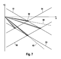
- FIG. 7 A modified method is to be explained, with which it is possible to plausibilize the objects with the help of time to collision and at the same time to solve the problem of "fake objects" in radar tracking.
- two objects are located by the radar sensor 10 and also by the video system.
- FIG. 7 As can be seen, however, the four straight lines 51-56 together form four intersections that could represent possible object data.
- the intersections are in FIG. 7 drawn as "Fehlellipsen” 58, each indicating the measurement inaccuracy in terms of distance and speed measurement. Only two of these intersections correspond to real objects, while the other two intersections are fake objects. The problem is to identify the two real objects among these four possible objects.
- the influence of the distance d rv between radar sensor and video camera can be easily taken into account in this method by the respective error ellipses 58 are shifted by this distance on the d-axis.
Landscapes
- Engineering & Computer Science (AREA)
- Radar, Positioning & Navigation (AREA)
- Remote Sensing (AREA)
- Physics & Mathematics (AREA)
- General Physics & Mathematics (AREA)
- Computer Networks & Wireless Communication (AREA)
- Electromagnetism (AREA)
- Radar Systems Or Details Thereof (AREA)
- Traffic Control Systems (AREA)
- Steering Control In Accordance With Driving Conditions (AREA)
- Networks Using Active Elements (AREA)
- Control Of Driving Devices And Active Controlling Of Vehicle (AREA)
Claims (6)
- Procédé de plausibilisation d'objets dans des systèmes d'assistance au conducteur de véhicules automobiles, dans lequel deux grandeurs de mesure (Tr, Tv) sont dérivées de données de localisation, provenant de deux systèmes (10; 16, 18) de localisation d'objets qui travaillent indépendamment l'un de l'autre dans le véhicule (46) d'un objet (48) qui a été localisé par les deux systèmes de localisation,
chacune des grandeurs de mesure correspondant à un système de localisation et les grandeurs de mesure représentant un seul et même paramètre physique (TTC), et
dans lequel la cohérence des deux grandeurs de mesure est ensuite vérifiée en les comparant, caractérisé en ce que
le paramètre (TTC) est le temps préalablement calculé qui s'écoulerait jusqu'à la collision du véhicule (46) avec l'objet (48). - Procédé selon la revendication 1, caractérisé en ce que l'un des deux systèmes de localisation (16, 18) est un système à base vidéo et en ce que la grandeur de mesure (Tv) qui lui est associée est calculée directement à partir de la modification de la taille apparente (s1, s2) de l'objet dans deux images vidéo (50, 52) enregistrées à des instants différents.
- Procédé selon les revendications 1 ou 2, caractérisé en ce que l'un des deux systèmes (10) de localisation d'objets est un radar FMCW.
- Procédé selon la revendication 3, caractérisé en ce que la grandeur de mesure (Tr) associée au radar FMCW est calculée sur base de la modification de la fréquence des signaux radar reçus en provenance de l'objet (48), qui est mesurée dans différents cycles de mesure du détecteur radar à des pentes de fréquence (R1s, R2s) qui présentent la même pente.
- Procédé selon les revendications 3 ou 4, caractérisé en ce que pour chaque objet (48) localisé par le radar FMCW, une relation entre la vitesse relative (v) et la distance (d) de l'objet est déterminée à l'aide du signal reçu sur une pente de modulation (R1s), la relation étant représentée par une droite (51, 53) dans un diagramme v/d, en ce que pour chaque objet, une autre relation est déterminée à l'aide du signal reçu sur une autre pente de modulation (R1f) qui présente une autre valeur de pente, la relation étant représentée par une autre droite (54, 56) dans le diagramme v/d, en ce que pour chaque point de concours entre les droites (51, 53, 54, 56), une grandeur de mesure (Tr) est calculée et en ce que ces grandeurs de mesure (Tr) sont comparées aux grandeurs de mesure (Tv) obtenues par le système de localisation (16, 18) à base vidéo.
- Procédé selon l'une des revendications précédentes, caractérisé en ce qu'en vue de la comparaison, l'effet exercé sur l'une des deux grandeurs de mesure (Tr, Tv) par la distance (drv) qui sépare les détecteurs (10, 16) des deux systèmes de localisation d'objets dans le sens de la longueur du véhicule (46) est corrigé.
Applications Claiming Priority (2)
| Application Number | Priority Date | Filing Date | Title |
|---|---|---|---|
| DE102007018470A DE102007018470A1 (de) | 2007-04-19 | 2007-04-19 | Fahrerassistenzsystem und Verfahren zur Objektplausibilisierung |
| PCT/EP2008/052562 WO2008128814A1 (fr) | 2007-04-19 | 2008-03-03 | Système d'assistance au conducteur et procédé pour améliorer la vraisemblance liée à des d'objets |
Publications (2)
| Publication Number | Publication Date |
|---|---|
| EP2140287A1 EP2140287A1 (fr) | 2010-01-06 |
| EP2140287B1 true EP2140287B1 (fr) | 2010-11-03 |
Family
ID=39539680
Family Applications (1)
| Application Number | Title | Priority Date | Filing Date |
|---|---|---|---|
| EP08717325A Active EP2140287B1 (fr) | 2007-04-19 | 2008-03-03 | Système d'assistance au conducteur et procédé pour améliorer la vraisemblance liée à des d'objets |
Country Status (7)
| Country | Link |
|---|---|
| US (1) | US8125372B2 (fr) |
| EP (1) | EP2140287B1 (fr) |
| JP (1) | JP2010501952A (fr) |
| CN (1) | CN101663594B (fr) |
| AT (1) | ATE487150T1 (fr) |
| DE (2) | DE102007018470A1 (fr) |
| WO (1) | WO2008128814A1 (fr) |
Families Citing this family (60)
| Publication number | Priority date | Publication date | Assignee | Title |
|---|---|---|---|---|
| DE102007018470A1 (de) * | 2007-04-19 | 2008-10-23 | Robert Bosch Gmbh | Fahrerassistenzsystem und Verfahren zur Objektplausibilisierung |
| DE102007049706A1 (de) | 2007-10-17 | 2009-04-23 | Robert Bosch Gmbh | Verfahren zur Schätzung der Relativbewegung von Video-Objekten und Fahrerassistenzsystem für Kraftfahrzeuge |
| CN102119340B (zh) | 2008-03-19 | 2014-10-22 | 阿维·佐哈尔 | 用于对物品和场所进行定位的系统和方法 |
| DE112008004069B4 (de) * | 2008-12-18 | 2014-09-04 | Toyota Jidosha Kabushiki Kaisha | Radarsystem |
| DE102009002626A1 (de) * | 2009-04-24 | 2010-10-28 | Robert Bosch Gmbh | Sensoranordnung für Fahrerassistenzsysteme in Kraftfahrzeugen |
| US20110025548A1 (en) * | 2009-07-31 | 2011-02-03 | Gm Global Technology Operations, Inc. | System and method for vehicle sensor fusion |
| US7978122B2 (en) * | 2009-08-13 | 2011-07-12 | Tk Holdings Inc. | Object sensing system |
| DE102009028742A1 (de) * | 2009-08-20 | 2011-02-24 | Robert Bosch Gmbh | Verfahren und Steuergerät zur Bestimmung einer Bewegungsinformation eines Objekts |
| CN102200578B (zh) * | 2010-03-25 | 2013-09-04 | 日电(中国)有限公司 | 数据关联设备和方法 |
| EP2463843B1 (fr) * | 2010-12-07 | 2015-07-29 | Mobileye Vision Technologies Ltd. | Méthode et système d'alerte de collision frontale |
| JP5772321B2 (ja) * | 2011-07-12 | 2015-09-02 | アイシン精機株式会社 | 車両検出装置、車両検出方法及びプログラム |
| WO2013010123A1 (fr) * | 2011-07-13 | 2013-01-17 | Avi Zohar | Système et procédé pour une meilleure recherche de direction de point à point |
| DE102011086433A1 (de) * | 2011-11-16 | 2013-05-16 | Robert Bosch Gmbh | Gedächtnisbehaftetes Manövrierassistenzsystem |
| DE102012200126A1 (de) * | 2012-01-05 | 2013-07-11 | Robert Bosch Gmbh | Fahrerassistenzdienst |
| DE102012202294B4 (de) * | 2012-02-15 | 2025-10-23 | Robert Bosch Gmbh | Verfahren und Kontrollsystem zur Plausibilisierung eines ersten Fahrerwunschsensors in Bezug auf einen zweiten zum ersten unterschiedlichen Fahrerwunschsensor eines Kraftfahrzeugs |
| EP2826685B1 (fr) * | 2012-03-15 | 2021-06-30 | Toyota Jidosha Kabushiki Kaisha | Appareil de commande de déplacement de véhicule |
| CN104321665B (zh) * | 2012-03-26 | 2017-02-22 | 罗伯特·博世有限公司 | 基于多表面模型的跟踪 |
| JP2013217799A (ja) * | 2012-04-10 | 2013-10-24 | Honda Elesys Co Ltd | 物体検知装置、物体検知方法、物体検知プログラム、及び動作制御システム |
| DE102012007986A1 (de) * | 2012-04-20 | 2013-10-24 | Valeo Schalter Und Sensoren Gmbh | Ferngesteuertes Rangieren eines Kraftfahrzeugsmithilfe eines tragbaren Kommunikationsgeräts |
| JP5497248B1 (ja) * | 2012-07-10 | 2014-05-21 | 本田技研工業株式会社 | 故障判定装置 |
| KR101380888B1 (ko) * | 2012-07-24 | 2014-04-02 | 현대모비스 주식회사 | 차간 거리 산출 장치 및 방법 |
| FR2996514B1 (fr) * | 2012-10-04 | 2014-11-28 | Pomagalski Sa | Procede et dispositif de controle d'un deplacement de plusieurs vehicules au sein d'une station d'un telepherique, notamment d'un telesiege ou telecabine |
| US9342986B2 (en) * | 2013-02-25 | 2016-05-17 | Honda Motor Co., Ltd. | Vehicle state prediction in real time risk assessments |
| US9050980B2 (en) | 2013-02-25 | 2015-06-09 | Honda Motor Co., Ltd. | Real time risk assessment for advanced driver assist system |
| US9746554B2 (en) * | 2013-04-09 | 2017-08-29 | Valeo Radar Systems, Inc. | Radar imaging system and related techniques |
| DE102013209736A1 (de) * | 2013-05-24 | 2014-11-27 | Robert Bosch Gmbh | Verfahren zur Bewertung von Hindernissen in einem Fahrerassistenzsystem für Kraftfahrzeuge |
| EP2821308B1 (fr) | 2013-07-03 | 2016-09-28 | Volvo Car Corporation | Système de véhicule pour commander des paramètres de sécurité de véhicule, véhicule et procédé pour commander des paramètres de sécurité |
| US9324233B2 (en) * | 2014-03-04 | 2016-04-26 | Nissan North America, Inc. | Vehicle contact warning method and system |
| US9574320B2 (en) * | 2014-03-26 | 2017-02-21 | Trimble Navigation Limited | Blended position solutions |
| DE102014213190A1 (de) | 2014-06-10 | 2015-12-17 | Robert Bosch Gmbh | Verfahren zur Objektortung mit einem FMCW-Radar |
| JP6285303B2 (ja) * | 2014-07-11 | 2018-02-28 | 株式会社デンソー | 車両制御装置 |
| JP6394228B2 (ja) | 2014-09-24 | 2018-09-26 | 株式会社デンソー | 物体検出装置 |
| JP6084192B2 (ja) * | 2014-10-15 | 2017-02-22 | 本田技研工業株式会社 | 物体認識装置 |
| EP3021134B1 (fr) * | 2014-11-13 | 2020-06-03 | Veoneer Sweden AB | Transfert de capteur |
| DE102015107392A1 (de) * | 2015-05-12 | 2016-11-17 | Valeo Schalter Und Sensoren Gmbh | Verfahren zum Erfassen eines Objekts in einer Umgebung eines Kraftfahrzeugs anhand von fusionierten Sensordaten, Steuereinrichtung, Fahrerassistenzsystem sowie Kraftfahrzeug |
| DE102015107391A1 (de) * | 2015-05-12 | 2016-11-17 | Valeo Schalter Und Sensoren Gmbh | Verfahren zum Steuern einer Funktionseinrichtung eines Kraftfahrzeugs anhand von fusionierten Sensordaten, Steuereinrichtung, Fahrerassistenzsystem sowie Kraftfahrzeug |
| KR102286174B1 (ko) * | 2015-09-01 | 2021-08-06 | 주식회사 만도 | 운전 지원 장치 및 운전 지원 방법 |
| CN105300439B (zh) * | 2015-10-19 | 2017-10-20 | 腾讯科技(深圳)有限公司 | 碰撞判断系统、方法及装置 |
| FR3047440B1 (fr) | 2016-02-10 | 2019-05-10 | Oberthur Fiduciaire Sas | Procede de fabrication de documents de securite et documents correspondants |
| US10317522B2 (en) * | 2016-03-01 | 2019-06-11 | GM Global Technology Operations LLC | Detecting long objects by sensor fusion |
| JP6600271B2 (ja) * | 2016-03-31 | 2019-10-30 | 株式会社デンソー | 物体認識装置及び物体認識方法 |
| JP6617677B2 (ja) * | 2016-10-19 | 2019-12-11 | 株式会社デンソー | 車両制御装置、車両制御方法 |
| CN118068830A (zh) * | 2016-12-15 | 2024-05-24 | 北京小米移动软件有限公司 | 控制平衡车运动的方法及装置、平衡车 |
| JP6787157B2 (ja) * | 2017-01-31 | 2020-11-18 | 株式会社デンソー | 車両制御装置 |
| US11061103B1 (en) | 2017-02-10 | 2021-07-13 | Iseeloc, Inc. | Navigation system, device and method using unsynchronized nodes |
| KR20190130614A (ko) | 2017-03-31 | 2019-11-22 | 에이캐럿큐브드 바이 에어버스 엘엘씨 | 외부 물체를 감지하기 위한 운송 수단 모니터링 시스템 및 방법 |
| DE102017206123A1 (de) * | 2017-04-10 | 2018-10-11 | Robert Bosch Gmbh | Verfahren und Vorrichtung zur Fusion von Daten verschiedener Sensoren eines Fahrzeugs im Rahmen einer Objekterkennung |
| EP3415943A1 (fr) | 2017-06-13 | 2018-12-19 | Veoneer Sweden AB | Estimation d'erreur pour un système de détection d'environnement de véhicule |
| JP6988200B2 (ja) * | 2017-06-29 | 2022-01-05 | 株式会社デンソー | 車両制御装置 |
| US11290470B2 (en) * | 2018-03-16 | 2022-03-29 | Onboard Security, Inc. | Misbehavior protection for connected vehicle communication |
| DE102018216809A1 (de) * | 2018-09-28 | 2020-04-02 | Robert Bosch Gmbh | Verfahren, Vorrichtung und Sensorsystem zur Umfelderfassung für ein Fahrzeug |
| DE102018009434A1 (de) * | 2018-11-30 | 2020-06-04 | Zf Active Safety Gmbh | Steuerungssystem und -Verfahren für ein Kraftfahrzeug zur Verarbeitung von mehrfach reflektierten Signalen |
| RU2742323C2 (ru) | 2018-12-29 | 2021-02-04 | Общество с ограниченной ответственностью "Яндекс Беспилотные Технологии" | Способ и компьютерное устройство для определения углового смещения радиолокационной системы |
| JP7185547B2 (ja) * | 2019-02-07 | 2022-12-07 | 株式会社デンソー | 車両検出装置 |
| JP7211145B2 (ja) * | 2019-02-20 | 2023-01-24 | トヨタ自動車株式会社 | 車両の制御装置 |
| DE102019112625A1 (de) * | 2019-05-14 | 2020-11-19 | Eyyes Gmbh | Verfahren zum Anzeigen und/oder Berechnen einer Relativbewegung |
| DE102019216517B3 (de) * | 2019-10-25 | 2021-03-18 | Daimler Ag | Verfahren zur Synchronisation zumindest zweier Sensor-Systeme |
| US11769412B2 (en) * | 2020-06-10 | 2023-09-26 | Hyundai Mobis Co., Ltd. | Rear side warning system and method for vehicle |
| CN112924972B (zh) * | 2021-01-28 | 2023-05-16 | 四川写正智能科技有限公司 | 基于毫米波进行智能测距和避障提醒的装置和方法 |
| DE102023200278A1 (de) * | 2023-01-16 | 2024-07-18 | Hitachi Astemo, Ltd. | Steuervorrichtung, Verfahren und Computerprogrammprodukt |
Family Cites Families (28)
| Publication number | Priority date | Publication date | Assignee | Title |
|---|---|---|---|---|
| US4860216A (en) * | 1986-11-13 | 1989-08-22 | The United States Of America As Represented By The Secretary Of The Air Force | Communication adaptive multi-sensor system |
| JPH08156723A (ja) * | 1994-12-06 | 1996-06-18 | Nissan Motor Co Ltd | 車両用障害物検出装置 |
| JP3491418B2 (ja) * | 1995-12-01 | 2004-01-26 | 株式会社デンソー | Fmcwレーダ装置 |
| GB2327821B (en) * | 1997-05-17 | 1999-12-01 | Bosch Gmbh Robert | Method and device for detecting an imminent or possible collision |
| WO2000073818A1 (fr) * | 1999-05-26 | 2000-12-07 | Robert Bosch Gmbh | Systeme de detection d'objet |
| US7852462B2 (en) * | 2000-05-08 | 2010-12-14 | Automotive Technologies International, Inc. | Vehicular component control methods based on blind spot monitoring |
| DE10133945A1 (de) * | 2001-07-17 | 2003-02-06 | Bosch Gmbh Robert | Verfahren und Vorrichtung zum Austausch und zur Verarbeitung von Daten |
| DE10133962A1 (de) * | 2001-07-17 | 2003-02-06 | Bosch Gmbh Robert | Verfahren zur Synchronisation und Vorrichtung |
| DE10149115A1 (de) | 2001-10-05 | 2003-04-17 | Bosch Gmbh Robert | Objekterfassungsvorrichtung |
| JP4019736B2 (ja) | 2002-02-26 | 2007-12-12 | トヨタ自動車株式会社 | 車両用障害物検出装置 |
| JP2004117071A (ja) * | 2002-09-24 | 2004-04-15 | Fuji Heavy Ind Ltd | 車外監視装置、及び、この車外監視装置を備えた走行制御装置 |
| JP3779280B2 (ja) * | 2003-03-28 | 2006-05-24 | 富士通株式会社 | 衝突予測装置 |
| JP4265931B2 (ja) * | 2003-05-22 | 2009-05-20 | 富士重工業株式会社 | 先行車両検出装置 |
| JP3918791B2 (ja) * | 2003-09-11 | 2007-05-23 | トヨタ自動車株式会社 | 物体検出装置 |
| JP2005209690A (ja) | 2004-01-20 | 2005-08-04 | Konica Minolta Photo Imaging Inc | Ccd撮像素子および撮像装置 |
| DE602005007006D1 (de) | 2004-04-08 | 2008-07-03 | Mobileye Technologies Ltd | Kollisionswarnsystem |
| JP2006011570A (ja) * | 2004-06-23 | 2006-01-12 | Daihatsu Motor Co Ltd | カメラキャリブレーション方法及びカメラキャリブレーション装置 |
| DE102004038494A1 (de) | 2004-08-07 | 2006-03-16 | Robert Bosch Gmbh | Verfahren und Vorrichtung zum Betreiben eines Sensorsystems |
| DE102004046360B4 (de) | 2004-09-24 | 2014-03-27 | Daimler Ag | Kraftfahrzeug mit einem präventiv wirkenden Schutzsystem |
| US20060091654A1 (en) * | 2004-11-04 | 2006-05-04 | Autoliv Asp, Inc. | Sensor system with radar sensor and vision sensor |
| DE102005005720A1 (de) | 2005-02-09 | 2006-08-17 | Robert Bosch Gmbh | Fahrerassistenzsystem mit redundanter Entscheidungseinheit |
| DE102005012945A1 (de) * | 2005-03-21 | 2006-09-28 | Robert Bosch Gmbh | Verfahren und Vorrichtung zu Abstands- und Relativgeschwindigkeitsmessung mehrerer Objekte |
| JP4557819B2 (ja) * | 2005-06-21 | 2010-10-06 | アルパイン株式会社 | 車両周辺情報提供装置 |
| JP4304517B2 (ja) * | 2005-11-09 | 2009-07-29 | トヨタ自動車株式会社 | 物体検出装置 |
| JP4595833B2 (ja) * | 2006-02-24 | 2010-12-08 | トヨタ自動車株式会社 | 物体検出装置 |
| DE102006058308A1 (de) * | 2006-12-11 | 2008-06-12 | Robert Bosch Gmbh | Verfahren und Vorrichtung zum Erfassen eines Hindernisses in einem Umgebungsbereich eines Kraftfahrzeugs und Kraftfahrzeug |
| DE102007018470A1 (de) * | 2007-04-19 | 2008-10-23 | Robert Bosch Gmbh | Fahrerassistenzsystem und Verfahren zur Objektplausibilisierung |
| DE102008042640B4 (de) * | 2008-10-07 | 2020-03-26 | Robert Bosch Gmbh | Verfahren und Vorrichtung zur Datenreduktion bei der Datenübermittlung an ein Fahrerassistenzsystem |
-
2007
- 2007-04-19 DE DE102007018470A patent/DE102007018470A1/de not_active Withdrawn
-
2008
- 2008-03-03 EP EP08717325A patent/EP2140287B1/fr active Active
- 2008-03-03 AT AT08717325T patent/ATE487150T1/de active
- 2008-03-03 DE DE502008001724T patent/DE502008001724D1/de active Active
- 2008-03-03 US US12/305,432 patent/US8125372B2/en not_active Expired - Fee Related
- 2008-03-03 JP JP2009526137A patent/JP2010501952A/ja active Pending
- 2008-03-03 CN CN2008800126958A patent/CN101663594B/zh not_active Expired - Fee Related
- 2008-03-03 WO PCT/EP2008/052562 patent/WO2008128814A1/fr not_active Ceased
Also Published As
| Publication number | Publication date |
|---|---|
| US20100085238A1 (en) | 2010-04-08 |
| CN101663594A (zh) | 2010-03-03 |
| DE502008001724D1 (de) | 2010-12-16 |
| ATE487150T1 (de) | 2010-11-15 |
| CN101663594B (zh) | 2013-03-27 |
| EP2140287A1 (fr) | 2010-01-06 |
| WO2008128814A1 (fr) | 2008-10-30 |
| DE102007018470A1 (de) | 2008-10-23 |
| US8125372B2 (en) | 2012-02-28 |
| JP2010501952A (ja) | 2010-01-21 |
Similar Documents
| Publication | Publication Date | Title |
|---|---|---|
| WO2008128814A1 (fr) | Système d'assistance au conducteur et procédé pour améliorer la vraisemblance liée à des d'objets | |
| DE102014103695B4 (de) | Fahrzeuggestützte Kreuzungsbeurteilungsvorrichtung und -programm | |
| DE102014101400B4 (de) | Zielerkennungsvorrichtung | |
| DE102008029613B4 (de) | Verfahren zur Schätzung der Elevation eines Zielobjekts unter Verwendung einer Radar-Datenfusion | |
| EP2200881B1 (fr) | Procédé pour évaluer le déplacement relatif d'objets vidéo et système d'assistance à la conduite pour des véhicules automobiles | |
| DE102016222776B4 (de) | Radarvorrichtung für Fahrzeuge und Zielbestimmungsverfahren für diese | |
| DE102018104243B3 (de) | Verfahren und System zur Erkennung von für ein Fahrzeug geeigneten Parklücken | |
| EP1577682B1 (fr) | Système de localisation d'objets pour véhicule automobile pour identifier des procédures de changement de voie | |
| DE112007000468T5 (de) | Radarvorrichtung und mobiles Objekt | |
| DE102007024391A1 (de) | Kollisionswarngerät mit Leitplankenerkennung | |
| EP2068173A1 (fr) | Procédé destiné à la mesure de mouvements obliques dans un système d'assistance au conducteur | |
| DE102011103795A1 (de) | Verfahren und System zur Kollisionsbewertung für Fahrzeuge | |
| EP2963631B1 (fr) | Procédé de détermination d'un stationnement à partir d'une pluralité de points de mesure | |
| EP3740784B1 (fr) | Procédé et dispositif de détection de mouvements transversaux critiques | |
| EP1158311B1 (fr) | Dispositif et procédé pour déterminer la distance et la vitesse | |
| DE102018202864A1 (de) | Verfahren und System für Synthetische-Apertur-Radarsignalverarbeitung | |
| DE102018202294A1 (de) | Schätzung von kartesischen Geschwindigkeiten von ausgedehnten Radarobjekten mit einem Radarsensor | |
| DE102020215424A1 (de) | Verfahren zur Bestimmung eines Eigengeschwindigkeits-Schätzwerts und eines Winkel-Schätzwerts von Zielen | |
| EP2221640B1 (fr) | Procédé de mesure de la vitesse d'un véhicule et affectation visible dans une documentation | |
| EP3374791A1 (fr) | Détection latérale de rail de sécurité par un capteur de distance dans le véhicule | |
| DE112015003914T5 (de) | Vorrichtung zum Erfassen einer axialen Fehlausrichtung | |
| EP3818511B1 (fr) | Procédé pour la classification de l'importance d'un objet | |
| EP1912844B1 (fr) | Procede pour produire des hypotheses relatives a l'environnement exterieur pour des fonctions d'assistance au conducteur | |
| EP1433002B1 (fr) | Procede pour determiner la position d'un objet cible et systeme radar actionne selon ledit procede | |
| DE102007058241A1 (de) | Auswerteverfahren, insbesondere für ein Fahrerassistenzsystem eines Kraftfahrzeugs, zur Objektdetektion mittels eines Radarsensors |
Legal Events
| Date | Code | Title | Description |
|---|---|---|---|
| PUAI | Public reference made under article 153(3) epc to a published international application that has entered the european phase |
Free format text: ORIGINAL CODE: 0009012 |
|
| 17P | Request for examination filed |
Effective date: 20091119 |
|
| AK | Designated contracting states |
Kind code of ref document: A1 Designated state(s): AT BE BG CH CY CZ DE DK EE ES FI FR GB GR HR HU IE IS IT LI LT LU LV MC MT NL NO PL PT RO SE SI SK TR |
|
| 17Q | First examination report despatched |
Effective date: 20100331 |
|
| GRAP | Despatch of communication of intention to grant a patent |
Free format text: ORIGINAL CODE: EPIDOSNIGR1 |
|
| DAX | Request for extension of the european patent (deleted) | ||
| GRAS | Grant fee paid |
Free format text: ORIGINAL CODE: EPIDOSNIGR3 |
|
| GRAA | (expected) grant |
Free format text: ORIGINAL CODE: 0009210 |
|
| AK | Designated contracting states |
Kind code of ref document: B1 Designated state(s): AT BE BG CH CY CZ DE DK EE ES FI FR GB GR HR HU IE IS IT LI LT LU LV MC MT NL NO PL PT RO SE SI SK TR |
|
| REG | Reference to a national code |
Ref country code: GB Ref legal event code: FG4D Free format text: NOT ENGLISH |
|
| REG | Reference to a national code |
Ref country code: CH Ref legal event code: EP |
|
| REG | Reference to a national code |
Ref country code: IE Ref legal event code: FG4D Free format text: LANGUAGE OF EP DOCUMENT: GERMAN |
|
| REF | Corresponds to: |
Ref document number: 502008001724 Country of ref document: DE Date of ref document: 20101216 Kind code of ref document: P |
|
| REG | Reference to a national code |
Ref country code: NL Ref legal event code: VDEP Effective date: 20101103 |
|
| LTIE | Lt: invalidation of european patent or patent extension |
Effective date: 20101103 |
|
| PG25 | Lapsed in a contracting state [announced via postgrant information from national office to epo] |
Ref country code: NO Free format text: LAPSE BECAUSE OF FAILURE TO SUBMIT A TRANSLATION OF THE DESCRIPTION OR TO PAY THE FEE WITHIN THE PRESCRIBED TIME-LIMIT Effective date: 20110203 Ref country code: LT Free format text: LAPSE BECAUSE OF FAILURE TO SUBMIT A TRANSLATION OF THE DESCRIPTION OR TO PAY THE FEE WITHIN THE PRESCRIBED TIME-LIMIT Effective date: 20101103 |
|
| REG | Reference to a national code |
Ref country code: IE Ref legal event code: FD4D |
|
| PG25 | Lapsed in a contracting state [announced via postgrant information from national office to epo] |
Ref country code: IS Free format text: LAPSE BECAUSE OF FAILURE TO SUBMIT A TRANSLATION OF THE DESCRIPTION OR TO PAY THE FEE WITHIN THE PRESCRIBED TIME-LIMIT Effective date: 20110303 Ref country code: HR Free format text: LAPSE BECAUSE OF FAILURE TO SUBMIT A TRANSLATION OF THE DESCRIPTION OR TO PAY THE FEE WITHIN THE PRESCRIBED TIME-LIMIT Effective date: 20101103 Ref country code: PT Free format text: LAPSE BECAUSE OF FAILURE TO SUBMIT A TRANSLATION OF THE DESCRIPTION OR TO PAY THE FEE WITHIN THE PRESCRIBED TIME-LIMIT Effective date: 20110303 Ref country code: LV Free format text: LAPSE BECAUSE OF FAILURE TO SUBMIT A TRANSLATION OF THE DESCRIPTION OR TO PAY THE FEE WITHIN THE PRESCRIBED TIME-LIMIT Effective date: 20101103 Ref country code: BG Free format text: LAPSE BECAUSE OF FAILURE TO SUBMIT A TRANSLATION OF THE DESCRIPTION OR TO PAY THE FEE WITHIN THE PRESCRIBED TIME-LIMIT Effective date: 20110203 Ref country code: SI Free format text: LAPSE BECAUSE OF FAILURE TO SUBMIT A TRANSLATION OF THE DESCRIPTION OR TO PAY THE FEE WITHIN THE PRESCRIBED TIME-LIMIT Effective date: 20101103 Ref country code: SE Free format text: LAPSE BECAUSE OF FAILURE TO SUBMIT A TRANSLATION OF THE DESCRIPTION OR TO PAY THE FEE WITHIN THE PRESCRIBED TIME-LIMIT Effective date: 20101103 Ref country code: FI Free format text: LAPSE BECAUSE OF FAILURE TO SUBMIT A TRANSLATION OF THE DESCRIPTION OR TO PAY THE FEE WITHIN THE PRESCRIBED TIME-LIMIT Effective date: 20101103 Ref country code: NL Free format text: LAPSE BECAUSE OF FAILURE TO SUBMIT A TRANSLATION OF THE DESCRIPTION OR TO PAY THE FEE WITHIN THE PRESCRIBED TIME-LIMIT Effective date: 20101103 |
|
| PG25 | Lapsed in a contracting state [announced via postgrant information from national office to epo] |
Ref country code: GR Free format text: LAPSE BECAUSE OF FAILURE TO SUBMIT A TRANSLATION OF THE DESCRIPTION OR TO PAY THE FEE WITHIN THE PRESCRIBED TIME-LIMIT Effective date: 20110204 |
|
| PG25 | Lapsed in a contracting state [announced via postgrant information from national office to epo] |
Ref country code: ES Free format text: LAPSE BECAUSE OF FAILURE TO SUBMIT A TRANSLATION OF THE DESCRIPTION OR TO PAY THE FEE WITHIN THE PRESCRIBED TIME-LIMIT Effective date: 20110214 Ref country code: CZ Free format text: LAPSE BECAUSE OF FAILURE TO SUBMIT A TRANSLATION OF THE DESCRIPTION OR TO PAY THE FEE WITHIN THE PRESCRIBED TIME-LIMIT Effective date: 20101103 Ref country code: IE Free format text: LAPSE BECAUSE OF FAILURE TO SUBMIT A TRANSLATION OF THE DESCRIPTION OR TO PAY THE FEE WITHIN THE PRESCRIBED TIME-LIMIT Effective date: 20101103 Ref country code: EE Free format text: LAPSE BECAUSE OF FAILURE TO SUBMIT A TRANSLATION OF THE DESCRIPTION OR TO PAY THE FEE WITHIN THE PRESCRIBED TIME-LIMIT Effective date: 20101103 |
|
| PG25 | Lapsed in a contracting state [announced via postgrant information from national office to epo] |
Ref country code: SK Free format text: LAPSE BECAUSE OF FAILURE TO SUBMIT A TRANSLATION OF THE DESCRIPTION OR TO PAY THE FEE WITHIN THE PRESCRIBED TIME-LIMIT Effective date: 20101103 Ref country code: DK Free format text: LAPSE BECAUSE OF FAILURE TO SUBMIT A TRANSLATION OF THE DESCRIPTION OR TO PAY THE FEE WITHIN THE PRESCRIBED TIME-LIMIT Effective date: 20101103 Ref country code: PL Free format text: LAPSE BECAUSE OF FAILURE TO SUBMIT A TRANSLATION OF THE DESCRIPTION OR TO PAY THE FEE WITHIN THE PRESCRIBED TIME-LIMIT Effective date: 20101103 Ref country code: RO Free format text: LAPSE BECAUSE OF FAILURE TO SUBMIT A TRANSLATION OF THE DESCRIPTION OR TO PAY THE FEE WITHIN THE PRESCRIBED TIME-LIMIT Effective date: 20101103 |
|
| PLBE | No opposition filed within time limit |
Free format text: ORIGINAL CODE: 0009261 |
|
| STAA | Information on the status of an ep patent application or granted ep patent |
Free format text: STATUS: NO OPPOSITION FILED WITHIN TIME LIMIT |
|
| BERE | Be: lapsed |
Owner name: ROBERT BOSCH G.M.B.H. Effective date: 20110331 |
|
| 26N | No opposition filed |
Effective date: 20110804 |
|
| PG25 | Lapsed in a contracting state [announced via postgrant information from national office to epo] |
Ref country code: MC Free format text: LAPSE BECAUSE OF NON-PAYMENT OF DUE FEES Effective date: 20110331 |
|
| REG | Reference to a national code |
Ref country code: DE Ref legal event code: R097 Ref document number: 502008001724 Country of ref document: DE Effective date: 20110804 |
|
| PG25 | Lapsed in a contracting state [announced via postgrant information from national office to epo] |
Ref country code: BE Free format text: LAPSE BECAUSE OF NON-PAYMENT OF DUE FEES Effective date: 20110331 Ref country code: IT Free format text: LAPSE BECAUSE OF FAILURE TO SUBMIT A TRANSLATION OF THE DESCRIPTION OR TO PAY THE FEE WITHIN THE PRESCRIBED TIME-LIMIT Effective date: 20101103 Ref country code: MT Free format text: LAPSE BECAUSE OF FAILURE TO SUBMIT A TRANSLATION OF THE DESCRIPTION OR TO PAY THE FEE WITHIN THE PRESCRIBED TIME-LIMIT Effective date: 20101103 |
|
| REG | Reference to a national code |
Ref country code: CH Ref legal event code: PL |
|
| PG25 | Lapsed in a contracting state [announced via postgrant information from national office to epo] |
Ref country code: LI Free format text: LAPSE BECAUSE OF NON-PAYMENT OF DUE FEES Effective date: 20120331 Ref country code: CH Free format text: LAPSE BECAUSE OF NON-PAYMENT OF DUE FEES Effective date: 20120331 |
|
| PG25 | Lapsed in a contracting state [announced via postgrant information from national office to epo] |
Ref country code: CY Free format text: LAPSE BECAUSE OF FAILURE TO SUBMIT A TRANSLATION OF THE DESCRIPTION OR TO PAY THE FEE WITHIN THE PRESCRIBED TIME-LIMIT Effective date: 20101103 Ref country code: LU Free format text: LAPSE BECAUSE OF NON-PAYMENT OF DUE FEES Effective date: 20110303 |
|
| PG25 | Lapsed in a contracting state [announced via postgrant information from national office to epo] |
Ref country code: TR Free format text: LAPSE BECAUSE OF FAILURE TO SUBMIT A TRANSLATION OF THE DESCRIPTION OR TO PAY THE FEE WITHIN THE PRESCRIBED TIME-LIMIT Effective date: 20101103 |
|
| PG25 | Lapsed in a contracting state [announced via postgrant information from national office to epo] |
Ref country code: HU Free format text: LAPSE BECAUSE OF FAILURE TO SUBMIT A TRANSLATION OF THE DESCRIPTION OR TO PAY THE FEE WITHIN THE PRESCRIBED TIME-LIMIT Effective date: 20101103 |
|
| REG | Reference to a national code |
Ref country code: AT Ref legal event code: MM01 Ref document number: 487150 Country of ref document: AT Kind code of ref document: T Effective date: 20130303 |
|
| PG25 | Lapsed in a contracting state [announced via postgrant information from national office to epo] |
Ref country code: AT Free format text: LAPSE BECAUSE OF NON-PAYMENT OF DUE FEES Effective date: 20130303 |
|
| REG | Reference to a national code |
Ref country code: FR Ref legal event code: PLFP Year of fee payment: 9 |
|
| REG | Reference to a national code |
Ref country code: FR Ref legal event code: PLFP Year of fee payment: 10 |
|
| REG | Reference to a national code |
Ref country code: FR Ref legal event code: PLFP Year of fee payment: 11 |
|
| PGFP | Annual fee paid to national office [announced via postgrant information from national office to epo] |
Ref country code: GB Payment date: 20240322 Year of fee payment: 17 |
|
| PGFP | Annual fee paid to national office [announced via postgrant information from national office to epo] |
Ref country code: FR Payment date: 20240320 Year of fee payment: 17 |
|
| PGFP | Annual fee paid to national office [announced via postgrant information from national office to epo] |
Ref country code: DE Payment date: 20250522 Year of fee payment: 18 |
|
| GBPC | Gb: european patent ceased through non-payment of renewal fee |
Effective date: 20250303 |
|
| PG25 | Lapsed in a contracting state [announced via postgrant information from national office to epo] |
Ref country code: GB Free format text: LAPSE BECAUSE OF NON-PAYMENT OF DUE FEES Effective date: 20250303 |
|
| PG25 | Lapsed in a contracting state [announced via postgrant information from national office to epo] |
Ref country code: FR Free format text: LAPSE BECAUSE OF NON-PAYMENT OF DUE FEES Effective date: 20250331 |