EP2140982A1 - Marteau perforateur et/ou marteau-piqueur - Google Patents
Marteau perforateur et/ou marteau-piqueur Download PDFInfo
- Publication number
- EP2140982A1 EP2140982A1 EP09161057A EP09161057A EP2140982A1 EP 2140982 A1 EP2140982 A1 EP 2140982A1 EP 09161057 A EP09161057 A EP 09161057A EP 09161057 A EP09161057 A EP 09161057A EP 2140982 A1 EP2140982 A1 EP 2140982A1
- Authority
- EP
- European Patent Office
- Prior art keywords
- unit
- firing pin
- drill
- racket
- catcher unit
- Prior art date
- Legal status (The legal status is an assumption and is not a legal conclusion. Google has not performed a legal analysis and makes no representation as to the accuracy of the status listed.)
- Withdrawn
Links
- 238000013016 damping Methods 0.000 claims abstract description 57
- 230000005540 biological transmission Effects 0.000 claims abstract description 36
- 238000010304 firing Methods 0.000 claims description 113
- 238000009527 percussion Methods 0.000 claims description 32
- 230000035939 shock Effects 0.000 claims description 7
- 230000036540 impulse transmission Effects 0.000 description 20
- 239000011324 bead Substances 0.000 description 4
- 239000000463 material Substances 0.000 description 3
- 239000012858 resilient material Substances 0.000 description 3
- 230000007704 transition Effects 0.000 description 2
- 229910000639 Spring steel Inorganic materials 0.000 description 1
- 230000002238 attenuated effect Effects 0.000 description 1
- 238000010276 construction Methods 0.000 description 1
- 238000005553 drilling Methods 0.000 description 1
- 229920001971 elastomer Polymers 0.000 description 1
- 239000000806 elastomer Substances 0.000 description 1
- 238000009434 installation Methods 0.000 description 1
- 238000002955 isolation Methods 0.000 description 1
Images


Classifications
-
- B—PERFORMING OPERATIONS; TRANSPORTING
- B25—HAND TOOLS; PORTABLE POWER-DRIVEN TOOLS; MANIPULATORS
- B25D—PERCUSSIVE TOOLS
- B25D17/00—Details of, or accessories for, portable power-driven percussive tools
- B25D17/06—Hammer pistons; Anvils ; Guide-sleeves for pistons
-
- B—PERFORMING OPERATIONS; TRANSPORTING
- B25—HAND TOOLS; PORTABLE POWER-DRIVEN TOOLS; MANIPULATORS
- B25D—PERCUSSIVE TOOLS
- B25D11/00—Portable percussive tools with electromotor or other motor drive
- B25D11/005—Arrangements for adjusting the stroke of the impulse member or for stopping the impact action when the tool is lifted from the working surface
-
- B—PERFORMING OPERATIONS; TRANSPORTING
- B25—HAND TOOLS; PORTABLE POWER-DRIVEN TOOLS; MANIPULATORS
- B25D—PERCUSSIVE TOOLS
- B25D17/00—Details of, or accessories for, portable power-driven percussive tools
- B25D17/24—Damping the reaction force
-
- B—PERFORMING OPERATIONS; TRANSPORTING
- B25—HAND TOOLS; PORTABLE POWER-DRIVEN TOOLS; MANIPULATORS
- B25D—PERCUSSIVE TOOLS
- B25D2222/00—Materials of the tool or the workpiece
- B25D2222/21—Metals
-
- B—PERFORMING OPERATIONS; TRANSPORTING
- B25—HAND TOOLS; PORTABLE POWER-DRIVEN TOOLS; MANIPULATORS
- B25D—PERCUSSIVE TOOLS
- B25D2222/00—Materials of the tool or the workpiece
- B25D2222/54—Plastics
- B25D2222/57—Elastomers, e.g. rubber
-
- B—PERFORMING OPERATIONS; TRANSPORTING
- B25—HAND TOOLS; PORTABLE POWER-DRIVEN TOOLS; MANIPULATORS
- B25D—PERCUSSIVE TOOLS
- B25D2250/00—General details of portable percussive tools; Components used in portable percussive tools
- B25D2250/191—Ram catchers for stopping the ram when entering idling mode
Definitions
- the invention relates to a drill and / or chisel hammer according to the preamble of claim 1.
- the invention relates to a drill and / or chisel hammer with a catcher unit and a percussion unit, which has at least one racket and a firing pin.
- catcher unit is intended to keep the striker in an idle range.
- "intended” should be understood to mean in particular specially equipped and / or specially designed.
- the term “catcher unit” should in particular define a unit which has at least one component that is provided to at least the firing pin and / or the firing pin together with the racket in an idle area and / or in a position, in particular in an idle position, catch and / or to keep in it, in particular to keep almost free of play in the position, wherein in the idle range and in particular in the idle position a shock pulse transmission of the firing pin and / or the racket is prevented on a tool located in a tool holder tool.
- percussion unit is to be understood here in particular a unit which has at least one component which is provided for generating and / or transmitting a pulse, in particular an axial impact pulse, on a tool.
- a component may in particular be a firing pin, a racket, a guide element, such as in particular a hammer tube and / or a piston, in particular a pot piston and / or further components that appear appropriate to the person skilled in the art.
- the term "idle range" should be understood here during operation of the drill and / or chisel hammer in particular a region within the percussion unit, in particular within a guide element for guiding the firing pin and / or the racket along a pulse transmission direction in which at least the Firing pin and / or the firing pin is located together with the racket during an idle position.
- the guide element is in particular formed by a tubular or cylindrical element, which is in particular provided to guide the racket and / or the firing pin axially along a pulse transmission direction of the percussion unit.
- the guide member may also be particularly advantageously formed integrally with a hammer tube and / or it may be integrally formed with a piston, such as a pot piston.
- the term "idle position" should be understood here during operation of the drill and / or chisel hammer in particular a position at least of the firing pin and / or the racket, in which the impact pulse transmission of the firing pin and / or the racket on a befindliches in a tool holder tool is prevented.
- the inventive design of the drill and / or chisel hammer advantageously a high level of user-friendliness can be achieved.
- a perceived as unpleasant for the operator noise can be at least reduced and / or prevented by an impulse transmission of the firing pin on another component in the no-load area, in particular after a lifting of the drill and / or chisel by the operator of a surface to be machined, can be prevented and thus a particular almost backlash-free positioning of the firing pin in the idle position can be achieved.
- Further, by holding the firing pin components that are in contact with the firing pin in the idle range can be advantageously spared because movement of the firing pin can be at least limited and / or prevented and thus also blows of the firing pin can be advantageously prevented on the components ,
- the catcher unit limits the firing pin in at least one operating position on one side in the direction of a striking area.
- operating position should be understood here in particular a position of the percussion unit of the drill and / or chisel hammer during operation, in which an operator presses the drill and / or chisel to a surface to be machined, lifts from this and / or holds in a position in which the drill and / or chisel is lifted from the surface to be machined, such as in particular an idle position and / or an impact position in which the impact pulse transmission of the firing pin and / or the racket on a befindliches in a tool holder tool is possible.
- the idle position of the firing pin and / or the racket should be understood here by the operating position.
- the term "impact area” should in particular define an area within the percussion unit along a pulse transmission direction during operation of the drill and / or hammer, in particular within a guide element for guiding the racket and / or the striker, in which at least the striker and / or or the racket is located during the impact pulse transmission and in which in particular in the striking position a shock pulse transmission of the racket on the firing pin in an operation of the drill and / or chisel hammer takes place.
- the term "unilaterally limited” is to be understood here as meaning in particular a limitation of a movement of the firing pin counter to the momentum transfer direction.
- the firing pin is held securely in the idle range and thus a compact catcher unit can be provided.
- the catcher unit is formed here by a stop for the firing pin, whereby further components, space, installation costs and costs can be saved.
- the firing pin bears against a convex region of the catcher unit opposite to the impulse transmission direction, which is arranged on a side of the catcher unit facing the firing pin.
- the pulse transmission direction here extends substantially parallel to a main direction of extension of the rotary and / or chisel hammer from the racket via the firing pin in the direction of a tool.
- the term "essentially parallel” is to be understood here in particular as meaning a direction which, relative to a reference direction, has a deviation, in particular less than 8 °, advantageously less than 5 ° and particularly advantageously less than 2 °.
- a "convex region” is intended to mean, in particular, an area with a convex surface facing the firing pin, in particular on the firing pin in at least one position of the firing pin, in particular the idling position, and / or along a radial direction of the firing pin and / or a guide element substantially inwardly facing, convex surface of the catcher unit can be understood.
- the convex region can also have another shape that appears appropriate to the person skilled in the art, such as, for example, ramp-shaped.
- a structurally simple contact surface for the firing pin in particular in the idle position, created and at the same time can be achieved that the firing pin in a transition to another operating position, in particular in the impact position, advantageous, in particular wear-reduced on the can slide along convex area.
- a damping unit is proposed, which is at least partially formed integrally with the catcher unit.
- a "damping unit” is to be understood here in particular as a unit which comprises at least one component, in particular a damping element, which is preferably provided for transmitting a shock pulse of the firing pin and / or the racket to a housing and / or at least one reduce the component associated with the housing.
- the damping unit advantageously serves at least partially for vibration isolation and / or vibration damping between the firing pin and / or the racket and / or the housing and / or the at least one component assigned to the housing.
- the term "integral" is to be understood to mean, in particular, one-piece and / or cast and / or formed as a component.
- the catcher unit is formed integrally with a damping element of the damping unit. It can be advantageously saved components and the cost of the drill and / or chisel hammer can be kept low.
- the damping unit comprises a damping element which is at least provided to at least partially decouple a component from at least one return pulse of the firing pin.
- a "kickback impulse” is to be understood here in particular as a percussion impulse of the firing pin, which is transmitted during the impulse transmission of the firing pin to the tool from the tool to the firing pin and is directed counter to the impulse transmission direction.
- the damping element is formed of a resilient material, such as a rubber-like material and / or a spring steel.
- the damping element may be formed by a plurality of components, such as preferably two O-rings, which are arranged in close proximity to each other and are preferably arranged in direct contact with each other, or the damping element may be particularly preferably formed by a single component. There are others, the expert as reasonable appearing variations of the damping element possible.
- the damping element By the damping element, the components which are located in the immediate vicinity of the firing pin can be advantageously spared, in particular, a stress and / or wear of the components can be reduced. In this way, a long service life of the components and thus also of the drill and / or chisel hammer can be achieved.
- the damping unit comprises a damping element which is provided to at least partially absorb at least one impact pulse of the racket.
- a damping element which is provided to at least partially absorb at least one impact pulse of the racket.
- at least partial decoupling of the firing pin from a percussion impulse of the racket, in particular in the idling position can be achieved.
- further components can be saved by means of such a design of the damping element.
- the damping element are adapted to a particular working condition of the drill and / or chisel advantageous.
- the catcher unit of the firing pin can basically be formed separately from a catcher unit of the racket.
- the catcher unit of the firing pin is at least partially formed integrally with the catcher unit of the racket.
- the one-piece design of the catcher unit advantageously further space can be saved structurally simple and also costs can be saved.
- the catcher unit has at least one inner contour, which is designed as a latching contour.
- inner contour is to be understood here in particular a contour of at least one component, preferably the catcher unit, in particular of the damping element, which runs along the pulse transmission direction at an inner cross section of the component, wherein the inner cross section through an opening in the component in the direction of Pulse transmission direction is formed and lies in a plane which extends along a pulse transmission direction.
- a “detent contour” is to be understood as meaning, in particular, a contour which is provided for a latching connection, preferably with the racket and / or the firing pin and / or a further component.
- the catcher unit can be kept compact and also a secure positioning of the racket and / or the firing pin can be achieved in the catcher unit. Furthermore, by adapting the contour to a specific working condition of the rotary and / or chisel hammer, a holding force of the catcher unit which is preferred for the working condition can advantageously be achieved.
- the latching contour has at least one latching recess which is provided to receive at least one holding region of the racket.
- a “detent recess” is to be understood here in particular as a recess which is at least provided to at least partially receive a component in one position and to hold and / or fix this component in this position.
- a “recess” is to be understood in this context, in particular a recess and / or a material recess in the catcher unit.
- the latching recess is preferably arranged on a surface facing inward in a radial direction of the catcher unit.
- the radial direction of the catcher unit is substantially perpendicular to the pulse transmission direction.
- holding area here defines in particular a region of the racket facing the firing pin, in particular a portion which has a smaller cross-section in the radial direction of the catcher unit or a smaller outer diameter than a maximum extent in the radial direction of the catcher unit.
- the holding region is preferably designed such that it essentially forms a counter contour to the catch contour of the catcher unit. In this way, the locking contour for securing the racket and / or the firing pin can be achieved structurally simple.
- the latching recess is formed on a damping element.
- the catch recess is arranged along an axial direction of the catcher unit in a central region of the catcher unit.
- the axial direction of the catcher unit extends substantially parallel to the pulse transmission direction.
- the catcher unit at least partially covers the racket and at least partially the firing pin in a radial direction of the catcher unit.
- the operating position of the idle position of the firing pin and / or the racket is formed.
- at least partially covered should be understood in terms of overlap of the firing pin in particular a coverage of a portion of the firing pin, in which a striking surface is arranged.
- the holding area and an area in which a striking surface is arranged should be understood here in particular.
- impact surface is to be understood here in particular as a surface of the firing pin and / or of the racket, which is arranged in a plane which extends in the radial direction of the catcher unit, wherein a surface normal vector of the striking surface runs essentially along the impulse transmission direction.
- the striking surface is intended to receive or transmit impact pulses.
- the firing pin is guided in at least one operating position against a pulse transmission direction at least partially through the catcher unit.
- the operating position of the impact position of the firing pin and / or the racket is formed.
- the term "partially passed through” is to be understood here in particular as meaning that at least one region of the firing pin with the impact surface is guided through the catcher unit, in particular through the damping element, counter to the impulse transmission direction. It can be advantageously achieved that the firing pin can be securely held in its idle position. The firing pin can thus only be moved into a striking area when a certain force is overcome in order to be guided through the catcher unit.
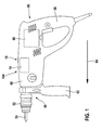
- FIG. 1 1 shows a drill and / or chisel hammer 10 according to the invention.
- the drill and / or chisel hammer 10 comprises a housing 48 and, in a front region 50, a tool holder 52 for receiving a tool 54.
- the drill bit comprises and / or chisel hammer 10 has a main handle 58 for operating the drill and / or chisel hammer 10 and for transmitting power from an operator to the drill and / or chisel hammer 10.
- the hammer and / or chisel hammer 10 is provided with a detachable auxiliary handle 62 executed.
- the auxiliary handle 62 can be detachably fastened to the drill and / or chisel hammer 10 via a latching connection or other connections that appear reasonable to the person skilled in the art.
- the auxiliary handle 62 is arranged to guide the drill and / or chisel hammer 10 by the operator in the vicinity of the tool holder 52 on the drill and / or chisel hammer 10.
- a main extension direction 64 of the rotary and / or hammer drill 10 extends from the main handle 58 in the direction of the tool holder 52.
- the hammer and / or chisel hammer 10 comprises a percussion device 104, which comprises a catcher unit 12 and a percussion unit 14.
- the drill and / or chisel hammer 10 has a drive unit 60.
- the drive torque of the drive unit 60 is transmitted via a non-illustrated transmission device of the drill and / or chisel hammer 10 for generating the impact pulse to the hammer mechanism unit 14 and for generating a rotational movement of the tool 54 via a guide member 66, which is designed here as a hammer tube to the tool holder 52 transmitted.
- the impact pulse of the percussion unit 14 is hereby generated in a manner known to those skilled in the art.
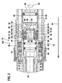
- FIG. 2 shows a sectional view of a first variant of the percussion unit 14 in an impact position.
- the drill and / or chisel hammer 10 comprises the catcher unit 12 and the percussion mechanism unit 14, which has at least one racket 16 and one striker pin 18.
- the catcher unit 12 is intended to hold the firing pin 18 in an idle region 20.
- the contact between the racket 16 and the firing pin 18 is prevented in an idling position, since the racket 16 and the firing pin 18 are arranged axially spaced along the main extension direction 64 (see. FIG. 3 ).
- the racket 16 and the firing pin 18 are mounted axially one behind the other along the main extension direction 64 of the drill and / or chisel hammer 10 in the guide element 66.
- the beater 16 and the firing pin 18 transmit in its impact position the impact pulse of the percussion unit 14 along a pulse transmission direction 24, which is parallel to the main extension direction 64, to the tool 54 located in the tool holder 52.
- the catcher unit 12 is disposed along the momentum transfer direction 24 in the percussion unit 14 in a region 70 which extends axially along the momentum transfer direction 24 and at least by a maximum extent of the striker 16 extending in a radial direction 46 of the catcher unit 12, and maximum extension of the firing pin 18, which also extends in the radial direction 46 of the catcher unit 12, is limited in an axial direction of the guide member 66.
- the catcher unit 12 comprises a damping element 32, two discs 76, 84 and a retaining ring 92. From the perspective of the impact position of the racket 16 along the pulse transmission direction 24 of the retaining ring 92 is arranged after the racket 16 6.
- the circlip 92 is held in this case in a groove which extends in a circumferential direction 94 of the guide member 66, wherein the retaining ring 92 serves as an axial securing the catcher unit 12 in the guide member 66 against the pulse transmission direction 24.
- the disc 76 On the retaining ring 92 is supported against the impulse transmission direction 24, the disc 76 from.
- the disc 76 is arranged in direct contact with the damping element 32, which has at least one inner contour 34 which is formed as a latching contour 36.
- the latching contour 36 has a latching recess 38, which is provided to receive at least one holding region 40 of the racket 16.
- the latching contour 36 or latching recess 38 merges in the direction of the racket 16 into a convex area 100 and in the direction of the firing pin 18 into a convex area 26 of the damping element 32 or catcher unit 12. Furthermore, the damping element 32 abuts along the pulse transmission direction 24 on the disc 84, thus the disc 84 along the pulse transmission direction 24 after the damping element 32 in stored the guide member 66. The disk 84 in turn rests against a shoulder 96 of the guide element 66. The shoulder 96 runs along the circumferential direction 94 of the guide element 66 and serves as an axial securing of the catcher unit 12 in the guide element 66 along the pulse transmission direction 24.
- the racket 16 and the firing pin 18 are brought by means of a pressing of the drill and / or chisel hammer 10 by an operator to a surface to be machined in its striking position.
- the tool 54 is displaced axially in the tool holder 52 counter to the main extension direction 64 and pushes the firing pin 18 from the idle region 20 into a striking region 22.
- the firing pin 18 slides along with a region 82 for impulse transmission along the convex region 26 of the catcher unit 12 and presses in this movement against the momentum transfer direction 24 the racket 16 from the recess 38 until the racket 16 has reached its stroke position.
- the area 82 of the firing pin 18 is moved by the movement of the tool 54 against the pulse transmission direction 24 through the latching recess 38 and along the convex portion 100 of the damping element 32 and the catcher unit 12 in the impact area 22.
- a striking surface 88 of the firing pin 18 protrudes against the impulse transmission direction 24 from the catcher unit 12 into the striking area 22.
- the firing pin 18 is at least partially guided by the catcher unit 12 in at least the striking position against the impulse transmission direction 24.
- the area 82 for impulse transmission of the firing pin 18 with the racket 16 is arranged on a side facing the racket 16 86 of the firing pin 18.
- the striking surface 88 of the firing pin 18 is arranged, whose surface normal vector points in the direction of the racket 16.
- the striking surface 88 of the firing pin 18 serves to impulse transmission between the racket 16 and the firing pin 18.
- the racket 16 also has a striking surface 90.
- the striking surface 90 of the racket 16 is arranged on the holding portion 40 of the racket 16 in the direction of the firing pin 18, wherein the surface normal vector of the striking surface 90 of the racket 16 in the direction of the firing pin 18 points.
- the drill and / or chisel hammer 10 has a damping unit 30, which is formed at least partially in one piece with the catcher unit 12.
- the damping unit 30 includes the damping element 32, which is at least provided to the guide member 66 and the drill and / or chisel hammer 10 in a striking position of the firing pin 18 of at least a return pulse of the firing pin 18 at least partially decoupled.
- the return pulse of the firing pin 18 by a stop portion 102 of the firing pin 18, the stopper portion 102 extends in the radial direction 46 over the region 82 for impulse transmission, guided by the disc 84 in the damping element 32.
- the disc 84 forms a stop for the stopper area 102 during a movement of the firing pin 18 against the pulse transmission direction 24.
- the damping element 32 is formed by a component made of resilient material.
- the guide element 66 and the components located in the immediate vicinity of the drill and / or chisel hammer 10 are at least partially decoupled from the return pulse of the firing pin 18 by the damping element 32.
- FIG. 3 shows a sectional view of the first variant of the percussion unit 14 in an idle position.
- the percussion unit 14 is brought by the operator by lifting a surface to be machined during operation of the drill and / or chisel hammer 10 from the impact position to the idle position.
- the tool 54 moves in the tool holder 52 along the main extension direction 64 of the drill and / or chisel hammer 10 in a percussion unit 14 facing away from the end position.
- a shock pulse transmission in the idle position on the tool 54 by the hammer mechanism unit 14 is thereby prevented.
- an idle control in particular a racket control
- the striker 16 and the striker 18 move to their idle positions after the tool 54 is already in the final position.
- the idle holes 68 are released in the guide member 66.
- the striker 18 is prevented by the catcher unit 12 from moving from its impact position to its idle position by moving against the momentum transfer direction 24.
- the catcher unit 12 limits the firing pin 18 in the idle position on one side Direction of the impact area 22.
- the firing pin 18 is in the idle position against the pulse transmission direction 24 with the region 82 for impulse transmission, which is also bead-like, at the convex portion 26 of the catcher unit 12, on a side facing the firing pin 18 side 28 of Catcher unit 12 is arranged.
- the convex portion 26 of the catcher unit 12 is disposed on the damping element 32 and thus serves as a stop of the firing pin 18 and the area 82 for impulse transmission in the idle position of the firing pin 18 in the direction of the impact area 22.
- a bead-edge area of the area 82 for impulse transmission which points in the direction of the racket 16, at the convex portion 26 of the catcher unit 12 at.
- a conically extending portion 72 in the guide member 66 as a stop for the firing pin 18 in the idle position of the firing pin 18.
- the catcher unit 12 is disposed between racket 16 and firing pin 18, that the firing pin 18 substantially free of play by means of the convex Area 26 of the catcher unit 12 and the conical portion 72 of the guide member 66 in the idle position of the firing pin 18 and in the idle region 20 is held.
- the racket 16 moves with the holding area 40 along the pulse transmission direction 24 into the damping element 32 until a side 74 of the racket 16 facing the catcher unit 12 strikes the pane 76.
- the holding portion 40 of the racket 16 has a smaller extent in the radial direction 46 of the catcher unit 12 than a maximum extension of the racket 16 in the radial direction 46 of the catcher unit 12 or the holding portion 40 of the racket 16 has a smaller outer diameter than the racket 16 itself, wherein the catcher unit 12 facing side 74 of the racket 16 is disposed in a region of the maximum extent of the racket 16.
- the disc 76 is arranged in direct contact with the damping element 32 and thus forms a component of the damping unit 30 and the catcher unit 12, respectively. Impact of the catcher unit 12 facing side 74 of the racket 16 on the disc 76 is transmitted from this to the damping element 32 and attenuated by the damping element 32.
- the damping member 32 is further provided to at least partially absorb the impact pulse of the striker 16 as the striker 16 moves to its idle position.
- the holding portion 40 of the racket 16 is held in the idle position of the racket 16 in the latching contour 36 and the latching recess 38 of the damping element 32, wherein the damping element 32 is at least partially formed by a catcher unit 12 of the racket 16.
- the catcher unit 12 is formed at least in one piece with the catcher unit 12 of the racket 16.
- the latching contour 36 or the latching recess 38 is shaped in such a way that the latching contour 36 or the latching recess 38 essentially corresponds in its shape to an outer contour 78 of the holding area 40 and thus forms a countercontour to the outer contour 78 of the holding area 40.
- the holding area 40 of the racket 16 is formed by a bead 80 which extends along the radial direction 46 of the catcher unit 12 in the direction of the guide element 66 and extends in the circumferential direction 94 of the guide element 66 about an end portion of the racket 16 facing the firing pin 18.
- the bead 80 is substantially completely received in the recess 38, whereby the racket 16 is caught securely.
- the latching recess 38 is arranged along an axial direction 42, which is aligned parallel to the pulse transmission direction 24, of the damping element 32 in a central region 44 of the damping element 32.
- the catcher unit 12 At least in the idling position of the racket 16 and the firing pin 18, the catcher unit 12 at least partially covers the racket 16 and at least partially the firing pin 18 in the radial direction 46 of the catcher unit 12, at least in the idle position.
- the holding area 40 or the bead 80 of FIG Bat 16 completely covered by the damping element 32.
- the region 82 for impulse transmission is partially covered by the damping element 32 and partially by the disc 84.
- FIG. 4 an alternative second variant of the percussion unit 14 is shown. Essentially, the same components, features and functions are always numbered the same. The following description is essentially limited to the differences from the first variant of the percussion unit 14 in the FIG. 3 , with respect to the same components, features and functions on the description of FIG. 3 can be referenced.
- a catcher unit 12 of the second variant of a percussion unit 14 is identical in construction to the first variant of the percussion unit 14.
- a racket 16 and a firing pin 18 are arranged in their idle position in a catcher unit 12 in direct contact with each other.
- a portion 82 of the firing pin 18 for impulse transmission has an additional neck 98 which extends axially against a portion 82 for impulse transmission 24.
- the additional neck 98 also extends opposite to the momentum transfer direction 24 via a bead-like Edge region of the region 82 for pulse transmission addition.
Landscapes
- Engineering & Computer Science (AREA)
- Mechanical Engineering (AREA)
- Percussive Tools And Related Accessories (AREA)
Applications Claiming Priority (1)
| Application Number | Priority Date | Filing Date | Title |
|---|---|---|---|
| DE200810040118 DE102008040118A1 (de) | 2008-07-03 | 2008-07-03 | Bohr- und/oder Meißelhammer |
Publications (1)
| Publication Number | Publication Date |
|---|---|
| EP2140982A1 true EP2140982A1 (fr) | 2010-01-06 |
Family
ID=40912048
Family Applications (1)
| Application Number | Title | Priority Date | Filing Date |
|---|---|---|---|
| EP09161057A Withdrawn EP2140982A1 (fr) | 2008-07-03 | 2009-05-26 | Marteau perforateur et/ou marteau-piqueur |
Country Status (2)
| Country | Link |
|---|---|
| EP (1) | EP2140982A1 (fr) |
| DE (1) | DE102008040118A1 (fr) |
Cited By (3)
| Publication number | Priority date | Publication date | Assignee | Title |
|---|---|---|---|---|
| CN104249334A (zh) * | 2013-06-27 | 2014-12-31 | 罗伯特·博世有限公司 | 手持式工具机冲击机构 |
| CN114555298A (zh) * | 2019-11-12 | 2022-05-27 | 喜利得股份公司 | 冲击机构布置 |
| US12528170B2 (en) | 2023-04-25 | 2026-01-20 | Milwaukee Electric Tool Corporation | Impact tool anvil with improved durability |
Families Citing this family (1)
| Publication number | Priority date | Publication date | Assignee | Title |
|---|---|---|---|---|
| DE102012220886A1 (de) * | 2012-11-15 | 2014-05-15 | Hilti Aktiengesellschaft | Werkzeugmaschine |
Citations (2)
| Publication number | Priority date | Publication date | Assignee | Title |
|---|---|---|---|---|
| DE102005035099A1 (de) * | 2005-07-27 | 2007-02-01 | Robert Bosch Gmbh | Schlagwerk und wenigstens schlagend antreibbare Handwerkzeugmaschine mit einem Schlagwerk |
| WO2007141080A1 (fr) * | 2006-06-06 | 2007-12-13 | Robert Bosch Gmbh | Mécanisme de percussion avec un percuteur et un dispositif d'arrêt affecté |
Family Cites Families (2)
| Publication number | Priority date | Publication date | Assignee | Title |
|---|---|---|---|---|
| DE3335553C2 (de) * | 1983-09-30 | 1994-02-24 | Black & Decker Inc | Bohrhammer mit Leerlauffangeinrichtung |
| DE4400779A1 (de) * | 1994-01-13 | 1995-07-20 | Duss Maschf | Elektropneumatischer Schlag- oder Drehschlaghammer |
-
2008
- 2008-07-03 DE DE200810040118 patent/DE102008040118A1/de not_active Withdrawn
-
2009
- 2009-05-26 EP EP09161057A patent/EP2140982A1/fr not_active Withdrawn
Patent Citations (2)
| Publication number | Priority date | Publication date | Assignee | Title |
|---|---|---|---|---|
| DE102005035099A1 (de) * | 2005-07-27 | 2007-02-01 | Robert Bosch Gmbh | Schlagwerk und wenigstens schlagend antreibbare Handwerkzeugmaschine mit einem Schlagwerk |
| WO2007141080A1 (fr) * | 2006-06-06 | 2007-12-13 | Robert Bosch Gmbh | Mécanisme de percussion avec un percuteur et un dispositif d'arrêt affecté |
Cited By (5)
| Publication number | Priority date | Publication date | Assignee | Title |
|---|---|---|---|---|
| CN104249334A (zh) * | 2013-06-27 | 2014-12-31 | 罗伯特·博世有限公司 | 手持式工具机冲击机构 |
| CN104249334B (zh) * | 2013-06-27 | 2018-02-27 | 罗伯特·博世有限公司 | 手持式工具机冲击机构 |
| CN114555298A (zh) * | 2019-11-12 | 2022-05-27 | 喜利得股份公司 | 冲击机构布置 |
| US12220801B2 (en) | 2019-11-12 | 2025-02-11 | Hilti Aktiengesellschaft | Impact mechanism arrangement |
| US12528170B2 (en) | 2023-04-25 | 2026-01-20 | Milwaukee Electric Tool Corporation | Impact tool anvil with improved durability |
Also Published As
| Publication number | Publication date |
|---|---|
| DE102008040118A1 (de) | 2010-01-07 |
Similar Documents
| Publication | Publication Date | Title |
|---|---|---|
| EP2729280B1 (fr) | Dispositif à percussion | |
| EP2448715B1 (fr) | Machine-outil portative | |
| DE60303406T2 (de) | Schlaghammer mit axialem Anschlag | |
| EP2448717B1 (fr) | Machine-outil portative | |
| DE3224176A1 (de) | Motorisch angetriebene schlagende handwerkzeugmaschine | |
| EP2448716B1 (fr) | Machine-outil portative | |
| EP2089192A1 (fr) | Unité massique vibratoire pour des machines-outils à main pourvues d'un dispositif de percussion | |
| EP2140982A1 (fr) | Marteau perforateur et/ou marteau-piqueur | |
| EP2561962B1 (fr) | Machine-outil manuelle | |
| DE102012212231A1 (de) | Handwerkzeugmaschine | |
| DE102010001683A1 (de) | Handwerkzeugmaschinenvorrichtung | |
| EP2560794A1 (fr) | Dispositif pour machine-outil portative | |
| DE102011075860A1 (de) | Werkzeugaufnahme | |
| EP1910039B1 (fr) | Mécanisme de percussion pour un outil portatif utilisé au moins en percussion | |
| EP1417076A1 (fr) | Machine-outil manuelle | |
| DE102012222639A1 (de) | Handwerkzeugmaschinenschlagwerkvorrichtung | |
| DE102004017940A1 (de) | Schlagwerk für eine Handwerkzeugmaschine | |
| DE3804026A1 (de) | Motorisch angetriebener meissel- oder bohrhammer | |
| EP2283978A2 (fr) | Dispositif de machine-outil manuelle | |
| EP2239100A2 (fr) | Dispositif de commande de percussion | |
| EP2674257B1 (fr) | Mécanisme de percussion | |
| EP2207644A1 (fr) | Machine-outil à main | |
| DE3039617A1 (de) | Bohrhammer | |
| DE102011079367A1 (de) | Schlagwerkvorrichtung | |
| DE3743333C2 (fr) |
Legal Events
| Date | Code | Title | Description |
|---|---|---|---|
| PUAI | Public reference made under article 153(3) epc to a published international application that has entered the european phase |
Free format text: ORIGINAL CODE: 0009012 |
|
| AK | Designated contracting states |
Kind code of ref document: A1 Designated state(s): AT BE BG CH CY CZ DE DK EE ES FI FR GB GR HR HU IE IS IT LI LT LU LV MC MK MT NL NO PL PT RO SE SI SK TR |
|
| STAA | Information on the status of an ep patent application or granted ep patent |
Free format text: STATUS: THE APPLICATION IS DEEMED TO BE WITHDRAWN |
|
| 18D | Application deemed to be withdrawn |
Effective date: 20100707 |