EP2283978A2 - Dispositif de machine-outil manuelle - Google Patents
Dispositif de machine-outil manuelle Download PDFInfo
- Publication number
- EP2283978A2 EP2283978A2 EP10166967A EP10166967A EP2283978A2 EP 2283978 A2 EP2283978 A2 EP 2283978A2 EP 10166967 A EP10166967 A EP 10166967A EP 10166967 A EP10166967 A EP 10166967A EP 2283978 A2 EP2283978 A2 EP 2283978A2
- Authority
- EP
- European Patent Office
- Prior art keywords
- tool device
- impact
- spring
- racket
- percussion
- Prior art date
- Legal status (The legal status is an assumption and is not a legal conclusion. Google has not performed a legal analysis and makes no representation as to the accuracy of the status listed.)
- Withdrawn
Links
- 238000013016 damping Methods 0.000 claims abstract description 44
- 238000009527 percussion Methods 0.000 claims description 43
- 239000000463 material Substances 0.000 description 3
- 238000010009 beating Methods 0.000 description 2
- 238000003780 insertion Methods 0.000 description 2
- 230000037431 insertion Effects 0.000 description 2
- 239000000725 suspension Substances 0.000 description 2
- 235000010678 Paulownia tomentosa Nutrition 0.000 description 1
- 240000002834 Paulownia tomentosa Species 0.000 description 1
- 230000001133 acceleration Effects 0.000 description 1
- 230000005540 biological transmission Effects 0.000 description 1
- 238000005553 drilling Methods 0.000 description 1
- 210000005069 ears Anatomy 0.000 description 1
- 238000009434 installation Methods 0.000 description 1
- 238000003801 milling Methods 0.000 description 1
- 238000005457 optimization Methods 0.000 description 1
- 230000003534 oscillatory effect Effects 0.000 description 1
Images


Classifications
-
- B—PERFORMING OPERATIONS; TRANSPORTING
- B25—HAND TOOLS; PORTABLE POWER-DRIVEN TOOLS; MANIPULATORS
- B25D—PERCUSSIVE TOOLS
- B25D17/00—Details of, or accessories for, portable power-driven percussive tools
- B25D17/06—Hammer pistons; Anvils ; Guide-sleeves for pistons
-
- B—PERFORMING OPERATIONS; TRANSPORTING
- B25—HAND TOOLS; PORTABLE POWER-DRIVEN TOOLS; MANIPULATORS
- B25D—PERCUSSIVE TOOLS
- B25D2217/00—Details of, or accessories for, portable power-driven percussive tools
- B25D2217/0011—Details of anvils, guide-sleeves or pistons
- B25D2217/0015—Anvils
-
- B—PERFORMING OPERATIONS; TRANSPORTING
- B25—HAND TOOLS; PORTABLE POWER-DRIVEN TOOLS; MANIPULATORS
- B25D—PERCUSSIVE TOOLS
- B25D2217/00—Details of, or accessories for, portable power-driven percussive tools
- B25D2217/0011—Details of anvils, guide-sleeves or pistons
- B25D2217/0019—Guide-sleeves
-
- B—PERFORMING OPERATIONS; TRANSPORTING
- B25—HAND TOOLS; PORTABLE POWER-DRIVEN TOOLS; MANIPULATORS
- B25D—PERCUSSIVE TOOLS
- B25D2250/00—General details of portable percussive tools; Components used in portable percussive tools
- B25D2250/085—Elastic behaviour of tool components
-
- B—PERFORMING OPERATIONS; TRANSPORTING
- B25—HAND TOOLS; PORTABLE POWER-DRIVEN TOOLS; MANIPULATORS
- B25D—PERCUSSIVE TOOLS
- B25D2250/00—General details of portable percussive tools; Components used in portable percussive tools
- B25D2250/371—Use of springs
Definitions
- the invention is based on a handheld power tool device according to the preamble of claim 1.
- From the DE 10 2006 060 320 A1 is already a hand tool device, in particular for a drill and / or percussion hammer, with at least one percussion having a racket, a percussion means, a spring means and a guide means, wherein the spring means is provided to accelerate the racket in at least one operating state and the guide means is provided for guiding the racket.
- the invention relates to a generic hand-held power tool device, in particular for a drill and / or percussion hammer, with at least one percussion having a racket, a percussion means, a spring means and a guide means, wherein the spring means is provided to the racket in at least one To accelerate operating condition and the guide means is provided to guide the bat.
- the percussion mechanism comprise a damping means which is connected in series with the spring means during at least one operating state.
- a "percussion mechanism” should be understood in particular to mean a device which is intended to generate a mechanical impact pulse and to forward it to an insertion tool.
- This is advantageous Schlagtechnik at least one component, which is intended to convert a rotational movement in a translational movement.
- the impact mechanism is designed as a hammer impact mechanism with a slotted guide, with a swash bearing and / or advantageously with an eccentric element.
- “Provided” is to be understood in particular to be specially equipped and / or designed.
- a "club” is to be understood as a unit which is intended to be accelerated by an element of the percussion mechanism and to deliver a mechanical impact pulse stored thereby essentially to the insert tool, in particular after an acceleration section.
- the racket is driven in translation driven.
- the spring means accelerates the racket relative to the racket means in a direction opposite to a direction of impact.
- the spring means is biased by a kinetic energy of the racket before a blow to the percussion means and stores in particular a part, preferably 1% to 20%, more preferably 2% to 10% of the kinetic energy of the racket.
- substantially is meant, when referring to an impulse, a force or an energy, in particular at least 80%, advantageously at least 90%, particularly advantageously at least 95%.
- direction of impact is to be understood in particular a direction which points from the racket in the direction of the impact means, preferably in the pulse direction, and which is preferably aligned parallel to a rotation axis of the insertion tool.
- the "percussion means” is preferably a striker or an anvil and is advantageously a separate means from the racket.
- the impact means transmits the impact pulse directly to the insert tool.
- a “spring means” is to be understood in particular as meaning a pneumatic spring, a spring that appears appropriate to the person skilled in the art, and / or advantageously a spiral spring.
- the spring means creates a particularly oscillatory system of piston, racket and percussion means, which supports the start of the racket on the percussion means.
- a “guiding means” is to be understood as a device which movably supports the racket parallel to the direction of impact.
- the guide means encloses the racket on at least one plane perpendicular to the direction of impact and is preferably designed as a hammer tube.
- the racket could enclose the guide means on at least one plane perpendicular to the direction of impact.
- a “damping means” is to be understood in particular as meaning a means to do so is provided, one element relative to another element, preferably until the elements are stationary relative to each other, decelerate.
- the damping means converts at least part of a kinetic energy into another form of energy, preferably heat energy.
- the damping means preferably has a modulus of elasticity which is at least ten times smaller than a modulus of elasticity of a part of the impact means and particularly preferably of a rubber-like material, in particular of an elastomeric plastic.
- the term "connected in series” should in this context be understood in particular to mean that at least one force acting parallel to the direction of impact is transmitted to a first means, preferably to the spring means and from the first means to a second means, preferably to the damping means becomes. Due to the inventive design of the power tool device advantageously the damping means for two tasks, in particular a damping of the percussion means and a suspension of the racket, can be used, whereby space, components, material costs and design effort can be saved and a simultaneously efficient suspension can be provided.
- the invention is based on a generic hand tool machine, wherein the spring means is arranged in a radially outer region of the guide means.
- An arrangement in a "radially outer region” is to be understood here in particular as meaning that the spring means is arranged at least partially, relative to an axis of symmetry of the guide means, on a larger radius than at least one region of an outer contour of the guide means pointing in the radial direction.
- the spring means surround the guide means.
- the spring means surrounds the guide means.
- the spring means the guide means on at least one plane, preferably substantially perpendicular to the Direction of impact is aligned, at least 180 °, preferably at least 270 ° surrounds.
- the term “substantially” should, when it refers to an angle, in particular a deviation of less than 30 °, advantageously less than 10 °, particularly advantageously less than 5 °, be understood.
- a corresponding configuration can advantageously be a simple spring means, in particular a coil spring, are used.
- a force flow is to be understood as meaning a path of a force and / or a moment in a component or a plurality of components from the point of application to a specific point, such as, in particular, a point at which it is picked up by a reaction force and / or a reaction moment.
- the damping means is intended to dampen the impact means.
- damping is to be understood in particular as meaning that the damping means at least partially converts a kinetic energy of the impact means into another form of energy.
- the damping means advantageously directs a pulse of the percussion means out of the impact mechanism.
- the damping means directs the pulse via the guide means on a housing of a hand tool, in which the hand tool device is installed.
- the impact mechanism has at least one movable stop element.
- a "stop element” is to be understood in particular an element which is intended to support a force in at least one direction.
- the stop element transmits a force in at least one direction, in particular by means of a positive connection of one first object on a second object. Due to the movable stop element structurally particularly simple an element, in particular the damping means, in a certain direction with a force loaded fulfill a function.
- the stop element is supported in at least one operating state, a force against a direction of impact, whereby the stop member can advantageously support a kickback of the insert tool.
- the stop element in at least one operating state transmits a force from the spring means to the damping means, whereby particularly advantageously the damping means can be used for two functions, which saves installation space and design effort.
- the percussion means have a fastening region to an attachment of the spring means.
- a "fastening area” is to be understood as meaning, in particular, an extension, a groove, a fastening means which appears expedient to the person skilled in the art, and / or advantageously a recess into which a turn of the spring means can be bent.
- the spring means is slidably mounted on the attachment area over a distance in the direction of impact. Due to the mounting area structurally simple, the spring means can be connected to the percussion means.
- the guide means has a securing unit which is provided to support the stop element.
- a "securing unit” is to be understood as meaning, in particular, a device that appears appropriate to a person skilled in the art, a radial recess in the guide means, a protrusion on the guide means and / or advantageously a securing ring.
- the stop element supports the damping means in at least one operating state on the guide means, whereby constructive Particularly simple impulse from the hand tool device out and in particular can be forwarded to the housing of the power tool.
- the stop element engage through the guide means in at least one region in the radial direction.
- pass through radial direction is to be understood in particular in a direction perpendicular to a direction of impact penetrate.
- the regions are arranged on at least two different sides of the guide means.
- “different” should be understood to mean, in particular, an angle of at least 45 °, advantageously at least 90 °, aligned with one another.
- the invention proceeds from a hand-held power tool with a hand-held power tool device, wherein any hand-held power tools that appear appropriate to the person skilled in the art, such as drills, rotary hammers, screwdrivers, milling machines, multifunction tools and / or in particular drills and / or percussion hammers for operation with the handheld power tool apparatus are conceivable, whereby a power tool device which can advantageously be tuned to the handheld power tool can be provided.
- any hand-held power tools that appear appropriate to the person skilled in the art, such as drills, rotary hammers, screwdrivers, milling machines, multifunction tools and / or in particular drills and / or percussion hammers for operation with the handheld power tool apparatus are conceivable, whereby a power tool device which can advantageously be tuned to the handheld power tool can be provided.
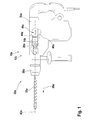
- FIG. 1 shows a hand tool 32a, which is designed as a percussion hammer.
- the hand tool 32a has a housing 34a and an insert tool attachment 36a. In the tool attachment 36a, an insert tool 38a is attached. Furthermore, the hand tool 32a has a gear unit 40a and an intermediate shaft, not shown.
- the transmission unit 40a splits a power flow caused by a non-illustrated motor into a power flow for a hammer mechanism 12a and a power flow for the intermediate shaft.
- the intermediate shaft drives a guide means 20a and the insert tool attachment 36a in rotation about a rotation axis 42a during a drilling operation.
- the handheld power tool 32a has a handheld power tool device 10a according to the invention with the hammer mechanism 12a.
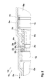
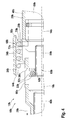
- the FIGS. 2 and 3 show parts of the hand tool device 10a in a sectional view.
- the percussion mechanism 12a during a percussive operation, generates a percussion impulse on the insert tool 38a in a direction of impact 26a that is parallel to the axis of rotation 42a and points in a main direction of operation, that is, from the insert tool fixture 36a toward the insert tool 38a.
- the percussion mechanism 12a comprises a racket 14a, a percussion means 16a, a spring means 18a, the guide means 20a, a piston 44a and an eccentric device 46a.
- the percussion mechanism 12a is arranged along the axis of rotation 42a in the direction of impact 26a in front of the insert tool attachment 36a.
- the guide means 20a has a hammer tube 48a.
- the beater 14a, the beating means 16a and the piston 44a are disposed within the guide means 20a.
- the guide means 20a, the racket 14a, the striking means 16a and the piston 44a axially, that is parallel to the direction of impact 26a, movable.
- the percussion means 16a has a mounting portion 28a for attachment of the spring means 18a.
- the attachment portion 28a is formed as a groove that surrounds the percussion means 16a in a circle about the rotation axis 42a. In the attachment region 28a, the spring means 18a is fixed along the stroke direction 26a by a distance bounded on one side by the groove and on the other hand by a damping means 22a.
- the spring means 18a is disposed coaxially with the guide means 20a within the guide means 20a and formed as a coil spring. It encloses the percussion means 16a on a side 50a of the racket 14a facing the racket 14a and extends in the direction of the racket 14a beyond the striking means 16a.
- the striking mechanism 12a has the damping means 22a.
- the damping means 22a surrounds the striking means 16a on a plane which is oriented perpendicular to the direction of impact 26a, and is arranged in the direction of impact 26a next to the guide means 20a.
- the damping means 22a has a ring made of an elastically and at least slightly plastically deformable material. In the direction of impact 26a and in a direction facing the axis of rotation 42a, the damping means 22a is supported by surfaces 52a of the impact means 16a.
- the striking mechanism 12a has a movable stop element 24a.
- the stop element 24a is formed as a dimensionally stable ring. It encloses the impact means 16a between the spring means 18a and the damping means 22a. The stop element 24a is carried along by the striking means 16 via the spring means 18a and the damping means 22a during movements of the striking means 16a.
- the guide means 20a has a securing unit 30a with a groove 54a and a securing means 56a.
- the groove 54a is inserted into the hammer tube 48a at an inner side of the hammer tube 48a, and surrounds the rotation shaft 42a annularly.
- the securing means 56a is formed as a dimensionally stable ring.
- the securing means 56a is partially disposed in the groove 54a and thus firmly connected to the hammer tube 48a. It partially points beyond an inner plane of the hammer tube 48a into an inner region of the hammer tube 48a.
- the securing unit 30a is arranged partially in the direction of impact 26a in front of the stop element 24a and can thus support the stop element 24a in a direction opposite to the direction of impact 26a.
- the motor drives, by means of the eccentric device 46a, the piston 44a in a translationally moved manner.
- FIG. 2 For example, the portable power tool apparatus 10a is shown in an operational state just before the racket 14a strikes the percussion means 16a. By means of an air cushion 58a, the piston 44a has previously accelerated the striker 14a in the direction of impact 26a. Before the racket 14a transmits a pulse to the percussion means 16a, the racket 14a hits the spring means 18a. The spring means 18a and the damping means 22a brake the racket 14a slightly and thereby store about 5% of a kinetic energy of the racket 14a.
- the spring means 18a brakes the racket 14a
- the spring means 18a and the damping means 22a are connected in series in a force flow.
- the flow of force acts between the beater 14a and the beating means 16a.
- the stopper member 24a transmits a force from the spring means 18a to the damping means 22a.
- the racket 14a hits the percussion means 16a
- the racket 14a transmits its impulse to the percussion means 16a.
- the percussion means 16a in turn transmits the impulse to the insert tool 38a.
- the pulse drives the insert tool 38a into a workpiece not shown in detail.
- the spring means 18a and the damping means 22a accelerate the racket 14a in a direction opposite to the direction of impact 26a, that is, toward the piston 44a.
- the piston 44a accelerates the beater 14a.
- Part of the pulse is reflected by the workpiece.
- the percussion means 16a is moved in a direction opposite to the impact direction 26a.
- the percussion means 16a moves the stopper member 24a, until this on the securing unit 30a hits.
- the damping means 22a then brakes the impact means 16a.
- the damping means 22a deforms and thus limited braking forces occurring.
- the stop element 24a supports a force acting on the stop element 24a by the damping means 22a, which force is aligned against the direction of impact 26a on the guide means 20a.
- FIGS. 4 and 5 a further embodiment of the invention is shown.
- the letter a in the reference numerals of the embodiment in the FIGS. 1 . 2 and 3 by the letter b in the reference numerals of the embodiment in the FIGS. 4 and 5 replaced.
- the following descriptions are essentially limited to the differences between the embodiments, with respect to the same components, features and functions on the description of the other embodiment in the FIGS. 1 . 2 and 3 can be referenced.
- FIGS. 4 and 5 show a hand tool device 10b invention of a hand tool 32b, as shown in FIG. 1 is shown.
- the handheld power tool apparatus 10b comprises a striking mechanism 12b comprising a club 14b, a striking means 16b, a spring means 18b and a guiding means 20b.
- the spring means 18b accelerates the racket 14b after striking in a direction opposite to the direction of impact 26b.
- the spring means 18b is arranged in a radially outer region of the guide means 20b and encloses the guide means 20b in a central region of the guide means 20b.
- the spring means 18b is arranged coaxially with the guide means 20b.
- the spring means 18b is movably guided parallel to the direction of impact 26b by a housing 34b of the portable power tool 32b.
- a guide means could guide a spring means on its outside.
- the percussion mechanism 12b has a first stop element 24b and a second stop element 25b. Both stop elements 24b and 25b are mounted movably on the guide means 20b parallel to the direction of impact 26b.
- the spring means 18b is arranged in a force flow coming from the first stop element 24b acts on the second stop element 25b via the spring means 18b.
- the first stop element 24b is arranged on a plane 60b which lies between a damping means 22b of the impact mechanism 12b and the spring means 18b and which is oriented perpendicular to the direction of impact 26b.
- the inner region 62b is annular and supports the damping means 22b in a direction opposite to the direction of impact 26b.
- the outer portions 64b are formed as formed on the inner portion 62b ears, these support the spring means 18b in the direction of impact 26b.
- the first stop element 24b supports the spring means 18b via the damping element 22b on the impact means 16b.
- the first stop element 24b supports a force acting on the damping element 22b by the impact means 16b on a securing unit 30b of the guide means 20b, via the outer regions 64b.
- the securing unit 30b is designed as a side of the recesses 66b of the guide means 20b which is opposite to the direction of impact 26b.
- the second stopper member 25b is disposed on a plane 68b that lies between the racket 14b and the percussion means 16b and is oriented perpendicular to the impact direction 26b.
- the second stopper member 25b has an outer portion 70b and two inner portions 72b.
- the outer portion 70b is annular, surrounds the guide means 20b, and is movably supported on the guide means 20b.
- the stopper elements 24b, 25b penetrate the guide means 20b perpendicular to the impact direction 26b in two areas which are arranged opposite one another.
- the inner portions 70b penetrate the guide means 20b and are partially disposed in an area in which the racket 14b is moved in a stroke. The racket causes a force on the second stop element 25b.
- the second stop member 25b transmits this force to the racket 14b side facing the spring means 18b.
- the stop element 25b is positively connected to the spring means.
- a stop element could be cohesively and / or non-positively connected to a spring means or partially formed integrally with a spring means.
Landscapes
- Engineering & Computer Science (AREA)
- Mechanical Engineering (AREA)
- Percussive Tools And Related Accessories (AREA)
Applications Claiming Priority (1)
| Application Number | Priority Date | Filing Date | Title |
|---|---|---|---|
| DE200910028506 DE102009028506A1 (de) | 2009-08-13 | 2009-08-13 | Handwerkzeugmaschinenvorrichtung |
Publications (2)
| Publication Number | Publication Date |
|---|---|
| EP2283978A2 true EP2283978A2 (fr) | 2011-02-16 |
| EP2283978A3 EP2283978A3 (fr) | 2013-06-12 |
Family
ID=43067094
Family Applications (1)
| Application Number | Title | Priority Date | Filing Date |
|---|---|---|---|
| EP10166967.9A Withdrawn EP2283978A3 (fr) | 2009-08-13 | 2010-06-23 | Dispositif de machine-outil manuelle |
Country Status (2)
| Country | Link |
|---|---|
| EP (1) | EP2283978A3 (fr) |
| DE (1) | DE102009028506A1 (fr) |
Cited By (3)
| Publication number | Priority date | Publication date | Assignee | Title |
|---|---|---|---|---|
| JP2013193142A (ja) * | 2012-03-16 | 2013-09-30 | Hitachi Koki Co Ltd | 打撃工具 |
| CN104227666A (zh) * | 2013-06-20 | 2014-12-24 | 苏州宝时得电动工具有限公司 | 一种电动榔头 |
| CN110394769A (zh) * | 2018-04-24 | 2019-11-01 | 博世电动工具(中国)有限公司 | 电动工具 |
Citations (1)
| Publication number | Priority date | Publication date | Assignee | Title |
|---|---|---|---|---|
| DE102006060320A1 (de) | 2006-12-20 | 2008-06-26 | Robert Bosch Gmbh | Schlagwerk für eine Handwerkzeugmaschine |
Family Cites Families (2)
| Publication number | Priority date | Publication date | Assignee | Title |
|---|---|---|---|---|
| DE836425C (de) * | 1948-10-02 | 1952-04-10 | Siemens Ag | Kurbelfederhammer |
| DE102007062798A1 (de) * | 2007-12-27 | 2009-07-02 | Robert Bosch Gmbh | Handwerkzeugmaschine |
-
2009
- 2009-08-13 DE DE200910028506 patent/DE102009028506A1/de not_active Withdrawn
-
2010
- 2010-06-23 EP EP10166967.9A patent/EP2283978A3/fr not_active Withdrawn
Patent Citations (1)
| Publication number | Priority date | Publication date | Assignee | Title |
|---|---|---|---|---|
| DE102006060320A1 (de) | 2006-12-20 | 2008-06-26 | Robert Bosch Gmbh | Schlagwerk für eine Handwerkzeugmaschine |
Cited By (4)
| Publication number | Priority date | Publication date | Assignee | Title |
|---|---|---|---|---|
| JP2013193142A (ja) * | 2012-03-16 | 2013-09-30 | Hitachi Koki Co Ltd | 打撃工具 |
| CN104227666A (zh) * | 2013-06-20 | 2014-12-24 | 苏州宝时得电动工具有限公司 | 一种电动榔头 |
| CN110394769A (zh) * | 2018-04-24 | 2019-11-01 | 博世电动工具(中国)有限公司 | 电动工具 |
| CN110394769B (zh) * | 2018-04-24 | 2022-03-01 | 博世电动工具(中国)有限公司 | 电动工具 |
Also Published As
| Publication number | Publication date |
|---|---|
| DE102009028506A1 (de) | 2011-02-17 |
| EP2283978A3 (fr) | 2013-06-12 |
Similar Documents
| Publication | Publication Date | Title |
|---|---|---|
| EP2646201B1 (fr) | Mécanisme de percussion à marteau | |
| DE102010062099A1 (de) | Hammerschlagwerk | |
| EP1967329A2 (fr) | Machine-outil manuelle dotée d'un mécanisme de frappe pneumatique | |
| EP2512750A1 (fr) | Machine-outil à main comportant un dispositif d'amortissement des vibrations | |
| EP2560794B1 (fr) | Dispositif pour machine-outil portative | |
| WO2021094213A1 (fr) | Ensemble mécanisme de percussion | |
| EP0663270B1 (fr) | Marteau à percussion rotative et/ou rectiligne | |
| EP2283978A2 (fr) | Dispositif de machine-outil manuelle | |
| EP2451615B1 (fr) | Appareil de forage et/ou percussion | |
| EP1910039B1 (fr) | Mécanisme de percussion pour un outil portatif utilisé au moins en percussion | |
| EP1935574B1 (fr) | Machine-outil manuelle dotée d'un mécanisme à percussion pneumatique | |
| EP2140982A1 (fr) | Marteau perforateur et/ou marteau-piqueur | |
| EP2646198B1 (fr) | Mécanisme de percussion à marteau | |
| EP2822734B1 (fr) | Dispositif de machine-outil portative | |
| EP2646203B1 (fr) | Mécanisme de percussion à marteau | |
| EP2307172B1 (fr) | Dispositif de percussion | |
| EP2512749B1 (fr) | Dispositif de machine-outil | |
| DE102012218882A1 (de) | Handwerkzeugmaschinenvorrichtung | |
| EP2674257A1 (fr) | Mécanisme de percussion | |
| DE102009045656A1 (de) | Werkzeugvorrichtung | |
| EP4733006A1 (fr) | Mécanisme de percussion pneumatique pour marteau perforateur ou marteau burineur | |
| WO2026093096A1 (fr) | Mécanisme de percussion pneumatique pour marteau perforateur ou marteau burineur | |
| DE102012209020A1 (de) | Handwerkzeugmaschinenschlagwerk | |
| DE102010030024A1 (de) | Schlagwerk |
Legal Events
| Date | Code | Title | Description |
|---|---|---|---|
| PUAI | Public reference made under article 153(3) epc to a published international application that has entered the european phase |
Free format text: ORIGINAL CODE: 0009012 |
|
| AK | Designated contracting states |
Kind code of ref document: A2 Designated state(s): AL AT BE BG CH CY CZ DE DK EE ES FI FR GB GR HR HU IE IS IT LI LT LU LV MC MK MT NL NO PL PT RO SE SI SK SM TR |
|
| AX | Request for extension of the european patent |
Extension state: BA ME RS |
|
| PUAL | Search report despatched |
Free format text: ORIGINAL CODE: 0009013 |
|
| AK | Designated contracting states |
Kind code of ref document: A3 Designated state(s): AL AT BE BG CH CY CZ DE DK EE ES FI FR GB GR HR HU IE IS IT LI LT LU LV MC MK MT NL NO PL PT RO SE SI SK SM TR |
|
| AX | Request for extension of the european patent |
Extension state: BA ME RS |
|
| RIC1 | Information provided on ipc code assigned before grant |
Ipc: B25D 17/06 20060101AFI20130508BHEP |
|
| STAA | Information on the status of an ep patent application or granted ep patent |
Free format text: STATUS: THE APPLICATION IS DEEMED TO BE WITHDRAWN |
|
| 18D | Application deemed to be withdrawn |
Effective date: 20131213 |