EP2140992B1 - Fabrication d'éléments structurels, notamment d'éléments de mur ou de façade, et élément structurel correspondant - Google Patents
Fabrication d'éléments structurels, notamment d'éléments de mur ou de façade, et élément structurel correspondant Download PDFInfo
- Publication number
- EP2140992B1 EP2140992B1 EP09008734A EP09008734A EP2140992B1 EP 2140992 B1 EP2140992 B1 EP 2140992B1 EP 09008734 A EP09008734 A EP 09008734A EP 09008734 A EP09008734 A EP 09008734A EP 2140992 B1 EP2140992 B1 EP 2140992B1
- Authority
- EP
- European Patent Office
- Prior art keywords
- dimensional arrangement
- parts
- material structure
- filling material
- exposed
- Prior art date
- Legal status (The legal status is an assumption and is not a legal conclusion. Google has not performed a legal analysis and makes no representation as to the accuracy of the status listed.)
- Not-in-force
Links
- 238000010276 construction Methods 0.000 title claims description 20
- 238000004519 manufacturing process Methods 0.000 title claims description 18
- 239000000463 material Substances 0.000 claims description 149
- 238000000034 method Methods 0.000 claims description 15
- 230000002093 peripheral effect Effects 0.000 claims description 6
- 239000002131 composite material Substances 0.000 claims description 5
- 239000011376 self-consolidating concrete Substances 0.000 claims description 5
- 239000011449 brick Substances 0.000 claims description 4
- 230000003014 reinforcing effect Effects 0.000 claims description 4
- 239000004567 concrete Substances 0.000 description 23
- 239000000945 filler Substances 0.000 description 15
- 239000004575 stone Substances 0.000 description 14
- 239000011476 clinker brick Substances 0.000 description 10
- 239000010410 layer Substances 0.000 description 10
- 239000011810 insulating material Substances 0.000 description 8
- 238000005266 casting Methods 0.000 description 5
- 150000001875 compounds Chemical class 0.000 description 5
- 238000000465 moulding Methods 0.000 description 5
- 229910000831 Steel Inorganic materials 0.000 description 4
- 238000009413 insulation Methods 0.000 description 4
- 239000011505 plaster Substances 0.000 description 4
- 239000010959 steel Substances 0.000 description 4
- 230000000007 visual effect Effects 0.000 description 4
- 239000000919 ceramic Substances 0.000 description 3
- 238000004132 cross linking Methods 0.000 description 3
- 230000000694 effects Effects 0.000 description 3
- 238000009415 formwork Methods 0.000 description 3
- 239000004033 plastic Substances 0.000 description 3
- 229920003023 plastic Polymers 0.000 description 3
- 239000011150 reinforced concrete Substances 0.000 description 3
- 230000002787 reinforcement Effects 0.000 description 3
- 239000007787 solid Substances 0.000 description 3
- 230000003068 static effect Effects 0.000 description 3
- XEEYBQQBJWHFJM-UHFFFAOYSA-N Iron Chemical compound [Fe] XEEYBQQBJWHFJM-UHFFFAOYSA-N 0.000 description 2
- 229910052918 calcium silicate Inorganic materials 0.000 description 2
- 239000000378 calcium silicate Substances 0.000 description 2
- OYACROKNLOSFPA-UHFFFAOYSA-N calcium;dioxido(oxo)silane Chemical compound [Ca+2].[O-][Si]([O-])=O OYACROKNLOSFPA-UHFFFAOYSA-N 0.000 description 2
- 239000004927 clay Substances 0.000 description 2
- 239000011538 cleaning material Substances 0.000 description 2
- 239000000835 fiber Substances 0.000 description 2
- 239000011521 glass Substances 0.000 description 2
- 229910052751 metal Inorganic materials 0.000 description 2
- 239000002184 metal Substances 0.000 description 2
- 230000003287 optical effect Effects 0.000 description 2
- 238000009418 renovation Methods 0.000 description 2
- 239000000126 substance Substances 0.000 description 2
- 239000000057 synthetic resin Substances 0.000 description 2
- 229920003002 synthetic resin Polymers 0.000 description 2
- 229920002430 Fibre-reinforced plastic Polymers 0.000 description 1
- 229910000746 Structural steel Inorganic materials 0.000 description 1
- 238000002441 X-ray diffraction Methods 0.000 description 1
- 239000000853 adhesive Substances 0.000 description 1
- 230000001070 adhesive effect Effects 0.000 description 1
- 239000002969 artificial stone Substances 0.000 description 1
- 239000004566 building material Substances 0.000 description 1
- 239000011509 cement plaster Substances 0.000 description 1
- 239000012792 core layer Substances 0.000 description 1
- 238000001514 detection method Methods 0.000 description 1
- 238000009826 distribution Methods 0.000 description 1
- 238000010616 electrical installation Methods 0.000 description 1
- 230000005672 electromagnetic field Effects 0.000 description 1
- 239000011151 fibre-reinforced plastic Substances 0.000 description 1
- 239000003365 glass fiber Substances 0.000 description 1
- 239000011211 glass fiber reinforced concrete Substances 0.000 description 1
- 239000010438 granite Substances 0.000 description 1
- 230000005484 gravity Effects 0.000 description 1
- 238000007654 immersion Methods 0.000 description 1
- 238000009434 installation Methods 0.000 description 1
- 229910052742 iron Inorganic materials 0.000 description 1
- 238000005304 joining Methods 0.000 description 1
- 239000007788 liquid Substances 0.000 description 1
- 239000004579 marble Substances 0.000 description 1
- 238000003801 milling Methods 0.000 description 1
- 239000000203 mixture Substances 0.000 description 1
- 239000004570 mortar (masonry) Substances 0.000 description 1
- 239000003973 paint Substances 0.000 description 1
- 235000011837 pasties Nutrition 0.000 description 1
- 230000035515 penetration Effects 0.000 description 1
- 239000002994 raw material Substances 0.000 description 1
- 238000000926 separation method Methods 0.000 description 1
- 239000010454 slate Substances 0.000 description 1
- 229910001220 stainless steel Inorganic materials 0.000 description 1
- 239000010935 stainless steel Substances 0.000 description 1
- 238000012916 structural analysis Methods 0.000 description 1
- 239000000758 substrate Substances 0.000 description 1
- XLYOFNOQVPJJNP-UHFFFAOYSA-N water Substances O XLYOFNOQVPJJNP-UHFFFAOYSA-N 0.000 description 1
Images


Classifications
-
- B—PERFORMING OPERATIONS; TRANSPORTING
- B28—WORKING CEMENT, CLAY, OR STONE
- B28B—SHAPING CLAY OR OTHER CERAMIC COMPOSITIONS; SHAPING SLAG; SHAPING MIXTURES CONTAINING CEMENTITIOUS MATERIAL, e.g. PLASTER
- B28B19/00—Machines or methods for applying the material to surfaces to form a permanent layer thereon
- B28B19/0053—Machines or methods for applying the material to surfaces to form a permanent layer thereon to tiles, bricks or the like
-
- E—FIXED CONSTRUCTIONS
- E04—BUILDING
- E04C—STRUCTURAL ELEMENTS; BUILDING MATERIALS
- E04C2/00—Building elements of relatively thin form for the construction of parts of buildings, e.g. sheet materials, slabs, or panels
- E04C2/02—Building elements of relatively thin form for the construction of parts of buildings, e.g. sheet materials, slabs, or panels characterised by specified materials
- E04C2/04—Building elements of relatively thin form for the construction of parts of buildings, e.g. sheet materials, slabs, or panels characterised by specified materials of concrete or other stone-like material; of asbestos cement; of cement and other mineral fibres
- E04C2/044—Building elements of relatively thin form for the construction of parts of buildings, e.g. sheet materials, slabs, or panels characterised by specified materials of concrete or other stone-like material; of asbestos cement; of cement and other mineral fibres of concrete
-
- E—FIXED CONSTRUCTIONS
- E04—BUILDING
- E04F—FINISHING WORK ON BUILDINGS, e.g. STAIRS, FLOORS
- E04F13/00—Coverings or linings, e.g. for walls or ceilings
- E04F13/07—Coverings or linings, e.g. for walls or ceilings composed of covering or lining elements; Sub-structures therefor; Fastening means therefor
- E04F13/08—Coverings or linings, e.g. for walls or ceilings composed of covering or lining elements; Sub-structures therefor; Fastening means therefor composed of a plurality of similar covering or lining elements
- E04F13/0862—Coverings or linings, e.g. for walls or ceilings composed of covering or lining elements; Sub-structures therefor; Fastening means therefor composed of a plurality of similar covering or lining elements composed of a number of elements which are identical or not, e.g. carried by a common web, support plate or grid
-
- E—FIXED CONSTRUCTIONS
- E04—BUILDING
- E04F—FINISHING WORK ON BUILDINGS, e.g. STAIRS, FLOORS
- E04F19/00—Other details of constructional parts for finishing work on buildings
- E04F19/02—Borders; Finishing strips, e.g. beadings; Light coves
-
- E—FIXED CONSTRUCTIONS
- E04—BUILDING
- E04C—STRUCTURAL ELEMENTS; BUILDING MATERIALS
- E04C2/00—Building elements of relatively thin form for the construction of parts of buildings, e.g. sheet materials, slabs, or panels
- E04C2002/005—Appearance of panels
- E04C2002/007—Panels with the appearance of a brick wall
Definitions
- the invention relates to a method for producing components, in particular of wall or facade elements, as a composite material precast elements for mounting on site or in a building.
- the invention further relates to components of this kind, which can be produced in particular according to the manufacturing method.
- Façades designed according to historical models often contain the mentioned natural stone moldings.
- natural stone any other suitable material (in particular concrete) can also be used to reproduce the historical form.
- historic facades often contain clinkered surfaces and / or plastered surfaces in addition to several natural stone moldings.
- facade elements that are manufactured as prefabricated parts for installation on buildings.
- a facade element known which consists of a plurality of thin plates of selected Stone material, such as granite or marble, is formed, wherein the plates are connected to each other on the back of anchors and glass reinforced concrete.
- the stone slabs are first arranged with the visible side down in a mold, then the anchors are mounted in the back of the plates and then both the plates and the anchors are coated with the glass fiber reinforced concrete.
- the curing of the mixture can take place within or without a supporting form.
- an insulating layer can subsequently be applied to the rear side, for example by being sprayed on or fastened by a plurality of glued-on pins with the aid of fastening means.
- a disadvantage of such facade elements and the corresponding manufacturing process are the complex attachment of the insulation and the fact that only plate-shaped, thin natural stone elements can be integrated into the finished cell.
- EP 1 270 839 A2 describes a prefabricated transportable component for the erection of walls and / or ceilings, with a concrete core and a voltage applied to the concrete core layer of bricks. At a distance from a formwork wall, a wall is built from the bricks and mortar and the space between the formwork wall and the wall is poured to form the concrete core with concrete.
- JP 10205053 A describes a concrete slab in which a large number of slate pieces are embedded to decorate one side or both sides of a wall surface in the manner of a mosaic.
- WO 2006/125590 A1 describes a method according to the preamble of claim 1 and an apparatus for producing Ferügteilbauriin.
- the concrete casting mold is filled with the visible side of the component of the precast component to be poured up with concrete and placed in the unbound concrete at least one natural stone by means of at least one holding element with an immersion depth for a secure connection with the concrete in a predetermined position and kept in this position until the concrete has received a strength holding the position of the at least one natural stone.
- EP 1 634 684 A2 describes a method of attaching components to ceilings and / or walls and a ceiling made with such a method according to the preamble of claim 9.
- each of several components On a flat surface of each of several components at least one anchor in at least one opening of the surface in the Inserted and fixed manner that each part of the anchor protrudes from the flat surface.
- the components are arranged on or on a formwork in such a way that the flat surfaces of the components essentially define a common surface. It is applied to the supporting part of a wall or ceiling molding compound on the flat surfaces, wherein the protruding parts of the anchors are embedded in the casting material and form a solid composite of the components with the cured casting compound after curing of the casting.
- the gap between the three-dimensional arrangement on the visible side and the rear material structure is filled with a filling material, so that the Filler permanently bonds the back material structure to the parts of the visual three-dimensional array and keeps the parts of the visual three-dimensional array in the desired position and orientation.
- a composite component is formed at least from the rear side material structure, the filling material and the parts of the visible three-dimensional arrangement.
- the rear-side material structure may be, for example, one or more elements of heat-insulating and / or sound-insulating material.
- the rear-side material structure in particular on the side facing the three-dimensional arrangement, can have one or more load-distributing plates which absorbs or absorbs at least the weight force exerted on the rear-side material structure by the filling material during and after filling of the filling material into the intermediate space and effects a distribution of this load on the substrate or the elements of the material structure underneath, for example, is suitable as a load-distributing plate, a plasterboard or calcium silicate plate.
- Self-compacting concrete is preferably used as filling material for filling the intermediate space.
- Self-compacting concrete is understood to mean concrete which vents only under the influence of gravity. It is therefore also called self-ventilating concrete. Such concrete is z.
- Self-compacting concrete another step in the development of the 5-substance concrete system
- filling material eg conventional concrete, plastic, in particular synthetic resin, concrete with plastic impact substances, in particular synthetic resin, and / or other materials suitable for joining the three-dimensional arrangement and the material structure.
- plastic in particular synthetic resin
- concrete with plastic impact substances in particular synthetic resin
- / or other materials suitable for joining the three-dimensional arrangement and the material structure e.g conventional concrete, plastic, in particular synthetic resin, concrete with plastic impact substances, in particular synthetic resin, and / or other materials suitable for joining the three-dimensional arrangement and the material structure.
- a reinforcement may be present, for example of steel, glass fibers, steel fibers and / or plastic fibers.
- the device may also be referred to as a hybrid device.
- the parts of the three-dimensional arrangement can be made of any solid, permanently dimensionally stable material, e.g. made of clay, ceramics, natural stone, artificial stone, concrete, glass.
- shaped pieces in different sizes and / or of different materials can be part of the three-dimensional arrangement on the visible side.
- the shaped pieces can be incorporated into different materials and differently structured surfaces formed by different materials from other parts of the three-dimensional arrangement.
- the components can be manufactured in such a way that, given any configuration of the three-dimensional arrangement on the visible side, they nevertheless satisfy the respective general technical structural-physical requirements with regard to statics, heat protection, sound insulation and / or fire protection.
- the components may be self-supporting and / or even designed so that they fulfill a supporting function for other parts of the building.
- the components can be designed as required for the interior or the exterior (in particular facade) of a building.
- the device when used as a facade element, can be hung on the outside of a supporting structure of the building.
- the back can be configured as a building wall for the interior.
- the surface of the component can be formed on the rear side by a plate-shaped element (such as, calcium silicate, plasterboard, natural stone slabs), which can also carry any paint.
- a plate-shaped element such as, calcium silicate, plasterboard, natural stone slabs
- additional elements include, for example, electric lines, water pipes, other lines (eg for gaseous media such as compressed air), built-in parts that are to be installed in walls of buildings (eg cabinets for building services) and / or steel plates or other Metal plates (eg to reinforce the device and / or as a shield against electromagnetic fields).
- molded parts, such as stucco can also be attached to the rear side.
- the three-dimensional arrangement can be produced on the visible side in an automated manner already in the factory in which the components are manufactured.
- a historical facade can be detected with optical means (eg by scanning) with respect to its three-dimensional shape, for example.
- optical means eg by scanning
- it can be planned, for example on the basis of photographs, how the visual page should be designed.
- computer files are created as a result of the planning or optical detection, which contains the information about the form to be produced on the visible side and optionally also the information about the materials to be used for this purpose.
- the visible side of the respective component can then be computer-controlled, for example produced using robots or other numerically controlled machines. Subsequently, the three-dimensional arrangement for the component can be assembled, positioned and aligned from the parts thus produced, in order then to connect them to the material structure at the rear side of the component via the filling material.
- the advantage of using computer files containing the information about the three-dimensional form on the visible side is that databases can be created which contain possible shapes, eg sorted by style epochs and / or by motifs.
- control of the method for producing the molded parts for the visible side eg Control parameters for a milling machine
- control parameters for a milling machine e.g Control parameters for a milling machine
- method steps in the production of other parts of the three-dimensional arrangement or the production of the arrangement of the various parts may also be stored in the computer file associated with the device to be manufactured.
- the component produced in particular according to the method described in this description has a three-dimensional arrangement of a plurality of parts which are to form a visible side of the component. It also has a material structure which forms a rear side of the component.
- a filler disposed between the visible three-dimensional array and the back material structure permanently bonds the back material structure with the parts of the three-dimensional three-dimensional array and holds and carries the parts of the three-dimensional visual system in the desired position and orientation.
- the filler material has been introduced into a gap between the face-side three-dimensional assembly and the backside material structure after the face-side assembly and the backside material structure have been positioned in the desired manner relative to each other.
- the filling material has entered into a permanent retaining connection both with the parts of the visible three-dimensional arrangement and with the material structure, which inserts it into the intermediate space has been. If the filling material had not been introduced into the intermediate space and it had not unfolded its binding effect there, an additional connection to the parts or to the material structure would be required, for example via an adhesive or an additional layer of the filling material.
- the invention has the advantage that the process for producing the compound is simpler.
- the compound produced by the filler material in a single step can be made more homogeneous and therefore more reliable.
- the risk of cavities and / or separations occurring at an interface between two connecting layers is eliminated.
- Another advantage is that the relative position and relative orientation of the material structure on the back side and the parts of the three-dimensional arrangement on the visible side (ie on the front side) can be adjusted precisely and after filling and curing or crosslinking of the filling material, these relative Position and alignment is maintained exactly.
- the material structure or parts of the visible side Arrangement subsequently attached to the filler material an exact positioning or alignment is at least very difficult to produce.
- X-ray diffraction analysis can be used to determine if the parts of the face-side assembly were down during fabrication of the component and, therefore, components of the filler material have moved down in joints between the visible portions. Traces or components are thus detectable.
- the three-dimensional arrangement may have at least one part which protrudes from a wall plane which is formed on the visible side by the three-dimensional arrangement.
- the protruding part can correspond to a historical architectural facade element of a building facade with regard to its form.
- a corresponding component therefore has a connecting element extending through the filling material, which connects at least part of the three-dimensional arrangement to the rear-side material structure.
- the connecting element may be made of metal, for example an iron material customary for concrete construction.
- the connecting element has a thread and cooperates with the thread another part of the connecting element, so that by a corresponding screwing the length of the connecting element and thus the distance between the part of the three-dimensional arrangement and the rear material structure can be adjusted. In this way an exact positioning and alignment is possible.
- the filling material preferably permanently fixes the set state of the connecting element, so that the connecting element also contributes to the fact that the relative position and relative orientation no longer change.
- the connector is configured such that it allows adjustment of its length and thus the distance between the back material structure and the at least part of the three-dimensional arrangement prior to introduction of the filler material, but not adjustment of the length of the connector in the finished component is more possible because the filling material firmly connects the rear material structure with the three-dimensional arrangement and / or because the filler fixes the connecting element in its set length.
- the connecting element can be designed so that it has a part in the manner of a telescope, which can be adjusted relative to the other part of the connecting element by pure linear movement.
- a measuring point is located on the component at at least one predefined location, the position of which and preferably also its orientation with respect to the component during positioning and alignment of the component on the building can be tracked. This makes it possible to move the component until the at least one measuring point (preferably several measuring points are provided) lies at a predefined position of the building.
- a recess and / or a projection is arranged on the component at a predefined position, preferably on a circumferential edge of the component, which lies between the visible side and the rear side.
- an adjacent component which is to form an adjacent part of the wall or facade, also has a corresponding projection and / or a corresponding recess at a predefined position of the component.
- control points can not only serve to position two adjacent components in a predetermined manner relative to each other. Rather, it can also be achieved with the aid of one or more control points on a component that the component is precisely positioned and aligned with other parts of the building (eg a load-bearing reinforced concrete structure).
- Control points can be realized, in particular, by integrating a body into the filling material or by fastening the body to a holder on a body, the body having a recess and / or a projection.
- the body z. B. a cavity whose walls are formed by the body and which has an opening on at least one side.
- the opening in the direction of an outer side of the component may in particular have a circular, rectangular or square cross section.
- the body is made of a dimensionally stable material having a low coefficient of thermal expansion.
- materials for the body are in particular fiber reinforced plastic, ceramic (especially technical ceramics) and / or stainless steel in question.
- Fig. 1 shows a component in three-dimensional view, with pointing to the right front a visible side S of the component 1 can be seen.
- the back R is accordingly left in the back in the illustration.
- the visible side S is formed by a large number of individual parts and building materials.
- profiled elements 3a-3d are arranged around the window opening in a frame-like manner around a window opening, which extends through the component 1, from the visible side S to the rear side R.
- the elements 3a-3d are shaped, for example, according to historical models and made of natural stone.
- Level wall surfaces around the window opening and around the elements 3 are formed by the material of a facade plaster (eg cement plaster), wherein the Cleaning material, like front left in Fig. 1 is recognizable, is supported by a plurality of clinker bricks 5, preferably clay. These clinker bricks 5 are also part of the three-dimensional arrangement on the visible side S.
- a facade plaster eg cement plaster
- clinker bricks 5 are also part of the three-dimensional arrangement on the visible side S.
- window opening is located on the visible side of a solid, preferably made of natural stone facade element 7, which was also formed according to historical templates and has a projecting beyond the outer wall plane defined by the plaster projection 7a. Also below the window opening 2 are parts 9 of the visible three-dimensional arrangement, which form on the visible side S a three-dimensional, not running in the plane of the plaster surface shape.
- the surface of the component 1 at the rear side R is formed by a layer 12 of heat-insulating material.
- This layer 12 is located at a distance to the parts 3, 5, 7, 9 at the front of the device 1.
- This space is filled by a filling material 10, which is preferably a summarizender concrete.
- a horizontal reinforcing element 11 a, 11 b is formed at the level of the structural elements 9 and at the level of the profiled part 7, a horizontal reinforcing element 11 a, 11 b, e.g. made of structural steel.
- control points can be formed at the peripheral edge of the component 1, from the edge pieces front left and top in Fig. 1 can be identified.
- control points (to explain the concept of control points see above) can be formed.
- Fig. 1 are two control points on the upwardly facing edge surface of the peripheral edge and are designated by the reference numeral 8.
- Fig. 1 shows the device 1 in an orientation, as would be the case on a building facade.
- the control points 8 the device can be accurately connected to adjacent facade elements, eg also inventively designed components.
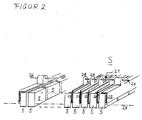
- Fig. 2 shows in three-dimensional, interrupted representation of a holding device 21, which has a plurality of clamping jaws 22.
- the jaws 22 serve to parts of the three-dimensional arrangement, here in the exemplary embodiment, the clinker bricks 5 of the device 1 according to Fig. 1 to hold while the filler material is filled in the space between the visible side three-dimensional arrangement and the rear material structure.
- the jaws 22 are elongated elements which extend in joints between the parts to be held. They are pressed by unspecified means, for example by air pressure, against each other, so as to clamp the parts to be held between them.
- the clamping jaws 22 at their visible outer edges each have a projecting part 24 which forms a through hole through which a single continuous rod 26 extends therethrough to position the clamping jaws 22 with respect to their penetration into the arrangement of the parts to be held ,
- the eyelets in parts 24 and the rod 26 cause, at least in the in Fig. 2 illustrated embodiment, the clamping pool 22 all the same distance from the in Fig. 2 projecting top side S in the joints between the clinker bricks 5.
- a dot-dash line 28 in Fig. 2 the depth level is indicated, up to the (in the Fig.
- the filling material 10 extends (eg again self-ventilating concrete), after the filling material in the space between the parts 5 of the three-dimensional arrangement and the in Fig. 2 was filled, not shown back material structure was filled.
- the clamping jaws 22 are relieved, so that they no longer clamp the clinker bricks 5 between them, and removed from the joints between the clinker bricks 5 upwards.
- Fig. 3 shows a similar device as the device 1 according to Fig. 1 during production.
- the rear material structure 12 for example, in turn made of a heat-insulating material, is arranged at the bottom, for example on a production table or a mold, which also forms a substantially flat support surface as in a production table and additionally (not in Fig. 3 shown) laterally towering Has walls to prevent leakage of the filling material laterally from the gap.
- the gap 40 is laterally closed by elements 39a, 39b (eg steel), wherein in the elements 39a, 39b each have a control point 31 a, 31 b is embedded or formed therein.
- These terminating elements 39 are preferably already arranged in the respective desired position prior to filling the filling material into the intermediate space 40 and are preferably connected both to parts of the three-dimensional arrangement (here a clinker brick 5 or a molded part 37) and also to the rear-side material structure 12.
- the closure elements 39 also have the function that they prevent leakage of the filling material in places. Therefore, no casting mold is needed at these locations.
- FIG. 3 Bottom left in Fig. 3 It can be seen that components required for the building can be embedded in the rear material structure, here for example a box 38 for an electrical installation.
- the reference numerals 43, 44, 45 designated plate-shaped objects (eg stone or a layer of plaster), wherein the plates also have projections can, as is the case with the objects 44, 45.
- the three-dimensional arrangement consists in the embodiment of Fig. 3 from three-dimensionally shaped parts 33, 36, 37, which are formed, for example, according to historical models, as well as substantially cuboidal elements 5, 32. Also, to form a substantially flat surface, for example, is formed on the outside of the visible side of a cleaning material 4, a plate-shaped object or material region 49 may be provided, which closes the gap between the parts 36, 37 in the embodiment.
- the intermediate space has at least one filling opening laterally at the peripheral edge of the overall arrangement and / or between the parts of the visible three-dimensional arrangement, through which the filling material is introduced into the intermediate space 40.
- vent openings are provided, can escape through the air from the gap 40, when the filler material is filled.
- the filling material After filling the filling material into the intermediate space 40, it is waited until the filling material has achieved its binding effect, e.g. until it has cured, set, and / or has formed crosslinking structures in the filler material. Thereafter, any holding devices that are not part of the component and / or molds may be removed.
- the finished component can now be used as a finished part for use in a building.
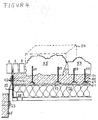
- This in Fig. 4 shown component is already mounted as part of a building to other parts of the building 65, for example via an armature 63 and other means.
- Fig. 4 The representation in Fig. 4 is to be understood schematically and does not correspond to the orientation of the device as a facade element to the building.
- the top in Fig. 4 represented visible side is located on the building rather on the outside of a facade, ie the representation according to Fig. 4 is drawn rotated by 90 °.
- Fig. 4 There are in Fig. 4 partly the same reference numerals as in Fig. 1 and Fig. 3 used.
- the elements and parts designated by the same reference numerals correspond to the parts and elements in FIG Fig. 1 and Fig. 3 or are the same with these.
- the following is on the peculiarities of the arrangement or the component in Fig. 4 received.
- Top in Fig. 4 is a cuboid block 54 drawn. However, this is a block of raw material from which part 55 is formed which is approximately in the middle of the arrangement of parts on the visible side is shown. On the right next to the part 55, a likewise elaborately formed part 53 can be seen. Left of the part 55 several clinker bricks 5 are again arranged.
- the part 55, but also the part 53 are connected by means of length-adjustable connecting elements 57 with the rear material structure 61, 12.
- a load-distributing plate 61 is provided, wherein the layer 12 and load-distributing plate 61 are both parts of the rear-side material structure.
- the plate 61 is bonded to the heat-insulating material 12.
- the load-distributing plate 61 has the function of distributing the loading forces exerted from above, in particular the parts 52, 55, but also of the filled filler uniformly over the surface of the rear material structure, so that the layer of insulating material 12 is not pressed in places.
- the load-distributing plate 61 preferably has the function of supporting the heat-insulating material 12.
- the material structure with the load-distributing plate 61 can also be used in other embodiments of a component.
- the length-adjustable connecting elements 57 are preferably attached to them formed feet 69 on the load-distributing plate 61, for example, glued or screwed.
- the length-adjustable connecting elements 57 have in their foot 69 an internal thread into which a rod-shaped element 71, which extends from the foot 69 to the bearing and to be positioned part 53, 55, with one on the rod-shaped element 71 trained external thread is screwed.
- the rod-shaped member 71 can be moved up or down so that the overall length of the connecting member changes and the part 53, 55 carried by the connecting member or members 57 is positioned at a corresponding distance from the load-distributing plate 61 becomes.
- the feet 69 of the links 57 may be fixed to the load distributing plate 61 (or, in alternative embodiments, to other parts of the backside material structure) (eg, by a locknut 73), so that the set Position and orientation of parts is secured on the visible side.
- the filling material can be filled in the intermediate space 60.
- the armature 63 is connected via a holding device with a defined breakpoint 42 on a side member 39 of the device with this.
- the armature 63 is adjustable at the stopping point 42 with respect to its relative position to the component (eg displaceably held and fixable in a guide). Therefore, an exact, positionally accurate attachment of the device to the building is possible.
Landscapes
- Engineering & Computer Science (AREA)
- Architecture (AREA)
- Civil Engineering (AREA)
- Structural Engineering (AREA)
- Chemical & Material Sciences (AREA)
- Ceramic Engineering (AREA)
- Mechanical Engineering (AREA)
- Finishing Walls (AREA)
Claims (13)
- Procédé servant à fabriquer des éléments de construction (1) en particulier des éléments de mur et de façade, en tant qu'éléments préfabriqués à base de matériau composite pour le montage sur site ou dans un édifice, sachant que :- des éléments (3, 5, 7, 9) d'un ensemble tridimensionnel constitué d'un ou de plusieurs matériaux, lesquels doivent former une face visible de l'élément de construction (1), sont disposés à une distance au-dessus d'une structure de matériau (12), qui doit former une face arrière de l'élément de construction (1) de telle sorte qu'un espace intermédiaire est formé entre l'ensemble tridimensionnel côté face visible et la structure de matériau (12) côté face arrière,caractérisé en ce que- en premier lieu des éléments (3, 5, 7, 9) de l'ensemble tridimensionnel côté face visible sont fixés dans une position et une orientation souhaitées, puis en ce qu'alors- l'espace intermédiaire entre l'ensemble tridimensionnel côté face visible et la structure de matériau (12) côté face arrière est rempli d'un matériau de remplissage (10) de telle sorte que le matériau de remplissage (10) relie de manière durable la structure de matériau (12) côté face arrière aux éléments (3, 5, 7, 9) de l'ensemble tridimensionnel côté face visible, en ce que le matériau de remplissage (10) maintient les éléments (3, 5, 7, 9) de l'ensemble tridimensionnel côté face visible dans la position et l'orientation souhaitées, et en ce que l'élément de construction (1) est formé au moins à partir de la structure de matériau (12) côté face arrière, à partir du matériau de remplissage (10) dans l'espace intermédiaire et à partir des éléments (3, 5, 5, 79) de l'ensemble tridimensionnel côté face visible.
- Procédé selon l'une quelconque des revendications précédentes, sachant que l'ensemble tridimensionnel présente au moins un élément (3, 7, 9), qui fait saillie d'un plan de mur formé au niveau de la face visible par l'ensemble tridimensionnel et dont la forme correspond en particulier à un élément de façade architectonique historique d'une façade d'édifice.
- Procédé selon l'une quelconque des revendications précédentes, sachant qu'au moins un élément (53, 55) de l'ensemble tridimensionnel est relié à la structure de matériau (12) côté face arrière par l'intermédiaire au moins d'un élément d'assemblage (57) avant que le matériau de remplissage (60) ne soit introduit dans l'espace intermédiaire.
- Procédé selon la revendication précédente, sachant que la modification de la longueur de l'élément d'assemblage (57) permet d'ajuster la distance entre la structure de matériau (12, 61) côté face arrière et l'élément (53, 55) au moins au nombre d'un de l'ensemble tridimensionnel avant que le matériau de remplissage (60) ne soit introduit dans l'espace intermédiaire.
- Procédé selon l'une quelconque des revendications précédentes, sachant qu'un évidement et/ou une partie faisant saillie sont disposés au moins en un emplacement (8) prédéfini au niveau d'un bord périphérique d'un élément de construction (1), lequel bord s'étend depuis la face visible jusqu'à la face arrière.
- Procédé selon l'une quelconque des revendications précédentes, sachant que l'espace intermédiaire entre l'ensemble tridimensionnel côté face visible et la structure de matériau (12) côté face arrière est rempli par, en tant que matériau de remplissage, du béton autocompactant.
- Procédé selon l'une quelconque des revendications précédentes, sachant que divers éléments de l'ensemble tridimensionnel, en particulier des briques creuses et/ou des briques dures (5), sont maintenus par le haut par un dispositif de maintien (21), tandis que l'espace intermédiaire est rempli d'un matériau de remplissage.
- Procédé selon l'une quelconque des revendications précédentes, sachant qu'une armature est appliquée au niveau de la face de l'ensemble tridimensionnel, orientée en direction de la structure de matériau (12) côté face arrière, avant que le matériau de remplissage ne soit introduit dans l'espace intermédiaire.
- Elément de construction (1), en particulier élément de mur ou de façade, et en particulier fabriqué selon l'une quelconque des revendications précédentes relatives au procédé, en tant qu'élément préfabriqué à base d'un matériau composite pour le montage sur site ou contre ou dans un édifice, sachant que l'élément de construction présente les éléments qui suivent :- un ensemble tridimensionnel constitué de plusieurs éléments (3, 5, 7, 9, 53, 55) formant une face visible de l'élément de construction (1),- une structure de matériau (12) qui forme une face arrière de l'élément de construction (1),- un matériau de remplissage (10), qui est disposé entre l'ensemble tridimensionnel côté face visible et la structure de matériau (12) côté face arrière, relie de manière durable la structure de matériau (12) côté face arrière aux éléments (3, 5, 7, 9, 53, 55) de l'ensemble tridimensionnel côté face visible et qui maintient et supporte les éléments (3, 5, 7, 9, 53, 55) de l'ensemble tridimensionnel côté face visible dans la position et l'orientation souhaitées,sachant- qu'au moins un élément (53, 55) de l'ensemble tridimensionnel est relié par l'intermédiaire au moins d'un élément d'assemblage (57), qui s'étend à travers le matériau de remplissage (60), à la structure de matériau (12, 61) côté face arrière,caractérisé en ce que
l'élément d'assemblage (57) présente un système d'ajustage de telle sorte qu'il est possible d'ajuster sa longueur et ainsi la distance entre la structure de matériau (12, 61) côté ace arrière et l'élément au moins au nombre d'un (53, 55) de l'ensemble tridimensionnel avant l'introduction du matériel de remplissage (60), sachant qu'il n'est toutefois plus possible, lorsque l'élément de construction (1) est finalisé, d'ajuster la longueur de l'élément d'assemblage (57), puisque le matériau de remplissage (60) relie la structure de matériau (12, 61) côté face arrière de manière fixe à l'ensemble tridimensionnel et/ou puisque le matériau de remplissage fixe l'élément d'assemblage dans sa longueur ajustée. - Elément de construction selon la revendication précédente, sachant que l'ensemble tridimensionnel présente au moins un élément (3, 7, 9), qui fait saillie du plan de mur formé par l'ensemble tridimensionnel au niveau de la face visible et dont la forme correspondant en particulier à un élément de façade architectonique historique d'une façade d'édifice.
- Elément de construction selon l'une quelconque des revendications 9 et 10, sachant qu'un évidement et/ou une partie faisant saillie sont disposés au moins en un emplacement (8) prédéfini au niveau d'un bord périphérique de l'élément de construction (1) qui s'étend depuis la face visible vers la face arrière.
- Elément de construction selon l'une quelconque des revendications 9 à 11, sachant que le matériau de remplissage est du béton autocompactant.
- Elément de construction selon l'une quelconque des revendications 9 à 12, sachant qu'une armature (57) est appliquée au niveau de la face de l'ensemble tridimensionnel orientée vers la structure de matériau côté face arrière, laquelle armature s'étend dans le matériau de remplissage et/ou s'étend à travers le matériau de remplissage vers la structure de matériau côté face arrière.
Applications Claiming Priority (1)
| Application Number | Priority Date | Filing Date | Title |
|---|---|---|---|
| DE200810031355 DE102008031355A1 (de) | 2008-07-04 | 2008-07-04 | Herstellung von Bauelementen, insbesondere von Wand- oder Fassadenelementen |
Publications (3)
| Publication Number | Publication Date |
|---|---|
| EP2140992A2 EP2140992A2 (fr) | 2010-01-06 |
| EP2140992A3 EP2140992A3 (fr) | 2010-11-10 |
| EP2140992B1 true EP2140992B1 (fr) | 2012-12-19 |
Family
ID=41165132
Family Applications (1)
| Application Number | Title | Priority Date | Filing Date |
|---|---|---|---|
| EP09008734A Not-in-force EP2140992B1 (fr) | 2008-07-04 | 2009-07-03 | Fabrication d'éléments structurels, notamment d'éléments de mur ou de façade, et élément structurel correspondant |
Country Status (2)
| Country | Link |
|---|---|
| EP (1) | EP2140992B1 (fr) |
| DE (1) | DE102008031355A1 (fr) |
Cited By (2)
| Publication number | Priority date | Publication date | Assignee | Title |
|---|---|---|---|---|
| EP3059354A1 (fr) | 2015-02-18 | 2016-08-24 | Ganzha, Vitalii V. | Module structurel et procédé de montage de modules structurels |
| US10626607B2 (en) * | 2018-09-06 | 2020-04-21 | Vitalii V. Ganzha | Multilayer structural module for construction |
Families Citing this family (2)
| Publication number | Priority date | Publication date | Assignee | Title |
|---|---|---|---|---|
| WO2011113694A1 (fr) * | 2010-03-17 | 2011-09-22 | Bauhaus-Universität Weimar | Béton autocompactant, son procédé de fabrication et utilisation de ce béton autocompactant pour réaliser une couche de béton |
| ITBO20100336A1 (it) * | 2010-05-31 | 2011-12-01 | Baraccani S N C Di Baraccani Giorg Io & C | Modulo prefabbricato avente pietre a facciavista e metodo per la sua fabbricazione |
Citations (1)
| Publication number | Priority date | Publication date | Assignee | Title |
|---|---|---|---|---|
| EP1634684A2 (fr) * | 2004-09-14 | 2006-03-15 | Managementgesellschaft Saaler Mühle GmbH & Co. Freizeitanlagen Betriebsgesellschaft KG | Procédé pour fixer des éléments de construction aux murs ou aux plafonds et construction obtenue par ce procédé |
Family Cites Families (8)
| Publication number | Priority date | Publication date | Assignee | Title |
|---|---|---|---|---|
| US4223502A (en) | 1978-03-08 | 1980-09-23 | Olympian Stone Company, Inc. | Building panel with stone facing and glass fiber reinforced concrete |
| JPH10205053A (ja) * | 1997-01-24 | 1998-08-04 | Hokushin Kogyo Kk | 石貼りコンクリートパネルと、その製造方法、及びその石貼りコンクリートパネルによる壁体構築方法 |
| DE19940188A1 (de) * | 1999-07-18 | 2001-03-22 | Gerhard Hierl | Verfahren und mobile Hebe- und Verlagevorrichtung zur Herstellung von Natursteinplatten |
| US6688073B2 (en) * | 2001-01-30 | 2004-02-10 | Chameleon Cast Wall System Llc | Method of forming a composite panel |
| EP1270839A3 (fr) * | 2001-06-19 | 2003-11-05 | Bertwin Schnubel | Elément de construction préfabriquée et transportable pour la réalisation de paroi et ou de plafond et procédé pour sa fabrication |
| CA2400122A1 (fr) * | 2002-08-28 | 2004-02-28 | Paul Baillargeon | Panneau mural mince prefabrique en beton |
| JP4606200B2 (ja) * | 2005-02-24 | 2011-01-05 | 三谷セキサン株式会社 | 石材埋設型ブロックの製造方法 |
| DE102005054087B3 (de) * | 2005-05-25 | 2007-01-04 | Rothermel, Jürgen | Verfahren und Vorrichtung zur Herstellung von Fertigteilbauelementen und Fertigteilbauelement |
-
2008
- 2008-07-04 DE DE200810031355 patent/DE102008031355A1/de not_active Withdrawn
-
2009
- 2009-07-03 EP EP09008734A patent/EP2140992B1/fr not_active Not-in-force
Patent Citations (1)
| Publication number | Priority date | Publication date | Assignee | Title |
|---|---|---|---|---|
| EP1634684A2 (fr) * | 2004-09-14 | 2006-03-15 | Managementgesellschaft Saaler Mühle GmbH & Co. Freizeitanlagen Betriebsgesellschaft KG | Procédé pour fixer des éléments de construction aux murs ou aux plafonds et construction obtenue par ce procédé |
Cited By (2)
| Publication number | Priority date | Publication date | Assignee | Title |
|---|---|---|---|---|
| EP3059354A1 (fr) | 2015-02-18 | 2016-08-24 | Ganzha, Vitalii V. | Module structurel et procédé de montage de modules structurels |
| US10626607B2 (en) * | 2018-09-06 | 2020-04-21 | Vitalii V. Ganzha | Multilayer structural module for construction |
Also Published As
| Publication number | Publication date |
|---|---|
| EP2140992A3 (fr) | 2010-11-10 |
| EP2140992A2 (fr) | 2010-01-06 |
| DE102008031355A1 (de) | 2010-01-14 |
Similar Documents
| Publication | Publication Date | Title |
|---|---|---|
| DE102011111318A1 (de) | Verfahren und Vorrichtung zur Herstellung eines lichtdurchlässigen Mehrschicht-Verbundbauelementes mit integrierter Fassadenplatte | |
| DE3790970C2 (de) | Fassadentafel | |
| EP2722466B1 (fr) | Système composite destiné à renforcer des éléments de construction | |
| EP2725164A2 (fr) | Structure de fixation pour un bâtiment doté d'un acrotère | |
| EP2140992A2 (fr) | Fabrication d'éléments structurels, notamment d'éléments de mur ou de façade | |
| DE19525082A1 (de) | Wandelement für Hochbauten und Verfahren zu seiner Herstellung | |
| DE19930567B4 (de) | Betonelement und Verfahren zum Herstellen eines Betonelementes | |
| EP1634684B1 (fr) | Procédé pour fixer des éléments de construction aux murs ou aux plafonds et construction obtenue par ce procédé ainsi que son utilisation | |
| DE102005054087B3 (de) | Verfahren und Vorrichtung zur Herstellung von Fertigteilbauelementen und Fertigteilbauelement | |
| DE3428827A1 (de) | Verfahren zur herstellung eines mauerwerkelementes, nach diesem verfahren hergestelltes mauerwerkelement und traegerplatte hierzu | |
| EP2601358B1 (fr) | Procédé de fabrication d'éléments préfabriqués | |
| EP0004604B1 (fr) | Marche d'escalier et sa méthode de fabrication | |
| DE202008009765U1 (de) | Leichtbaumauersystem | |
| DE102014108566A1 (de) | Brandabschottung für Trockenbauwände | |
| AT525045B1 (de) | Verfahren zur Herstellung einer Raumzelle und eines Raumzellenteils | |
| DE102012021213A1 (de) | Randschalungselement und Randschalungs-Verfahren | |
| DE896860C (de) | In sich vorgespanntes Bewehrungselement aus Formsteinen | |
| DE202004019390U1 (de) | Fertigteil | |
| DE10118288A1 (de) | Verfahren und Vorrichtung zur Herstellung von Wandbauelementen mit einer Putzbeschichtung sowie entprechendes Wandbauelement | |
| DE4029560A1 (de) | Verfahren zur herstellung eines hohlbodens | |
| AT517855A4 (de) | Bausatz für einen Brüstungsaufbau | |
| DE4425057A1 (de) | Bauelement | |
| DE19931034C2 (de) | Verfahren und System zur Montage von Platten an einem Körper | |
| DE3241631A1 (de) | Verfahren und vorrichtung zur herstellung kunststoffbeschichteter bauelemente | |
| EP1671768A1 (fr) | Elément préfabriqué avec des pièrres naturelles et procédé de fabrication d'un tel élément |
Legal Events
| Date | Code | Title | Description |
|---|---|---|---|
| PUAI | Public reference made under article 153(3) epc to a published international application that has entered the european phase |
Free format text: ORIGINAL CODE: 0009012 |
|
| AK | Designated contracting states |
Kind code of ref document: A2 Designated state(s): AT BE BG CH CY CZ DE DK EE ES FI FR GB GR HR HU IE IS IT LI LT LU LV MC MK MT NL NO PL PT RO SE SI SK SM TR |
|
| PUAL | Search report despatched |
Free format text: ORIGINAL CODE: 0009013 |
|
| AK | Designated contracting states |
Kind code of ref document: A3 Designated state(s): AT BE BG CH CY CZ DE DK EE ES FI FR GB GR HR HU IE IS IT LI LT LU LV MC MK MT NL NO PL PT RO SE SI SK SM TR |
|
| AX | Request for extension of the european patent |
Extension state: AL BA RS |
|
| 17P | Request for examination filed |
Effective date: 20110510 |
|
| 17Q | First examination report despatched |
Effective date: 20111221 |
|
| REG | Reference to a national code |
Ref country code: DE Ref legal event code: R079 Ref document number: 502009005710 Country of ref document: DE Free format text: PREVIOUS MAIN CLASS: B28B0019000000 Ipc: E04C0002040000 |
|
| RIC1 | Information provided on ipc code assigned before grant |
Ipc: E04C 2/04 20060101AFI20120425BHEP Ipc: E04C 1/40 20060101ALI20120425BHEP Ipc: E04F 13/08 20060101ALI20120425BHEP Ipc: B28B 19/00 20060101ALI20120425BHEP Ipc: E04F 19/02 20060101ALI20120425BHEP |
|
| GRAP | Despatch of communication of intention to grant a patent |
Free format text: ORIGINAL CODE: EPIDOSNIGR1 |
|
| RAP1 | Party data changed (applicant data changed or rights of an application transferred) |
Owner name: DRAEGER, KAI |
|
| GRAS | Grant fee paid |
Free format text: ORIGINAL CODE: EPIDOSNIGR3 |
|
| GRAA | (expected) grant |
Free format text: ORIGINAL CODE: 0009210 |
|
| RAP1 | Party data changed (applicant data changed or rights of an application transferred) |
Owner name: NEUMANN, JENS ULRICH Owner name: DRAEGER, KAI |
|
| AK | Designated contracting states |
Kind code of ref document: B1 Designated state(s): AT BE BG CH CY CZ DE DK EE ES FI FR GB GR HR HU IE IS IT LI LT LU LV MC MK MT NL NO PL PT RO SE SI SK SM TR |
|
| REG | Reference to a national code |
Ref country code: GB Ref legal event code: FG4D Free format text: NOT ENGLISH |
|
| REG | Reference to a national code |
Ref country code: CH Ref legal event code: EP |
|
| REG | Reference to a national code |
Ref country code: AT Ref legal event code: REF Ref document number: 589515 Country of ref document: AT Kind code of ref document: T Effective date: 20130115 |
|
| REG | Reference to a national code |
Ref country code: DE Ref legal event code: R096 Ref document number: 502009005710 Country of ref document: DE Effective date: 20130228 |
|
| PG25 | Lapsed in a contracting state [announced via postgrant information from national office to epo] |
Ref country code: LT Free format text: LAPSE BECAUSE OF FAILURE TO SUBMIT A TRANSLATION OF THE DESCRIPTION OR TO PAY THE FEE WITHIN THE PRESCRIBED TIME-LIMIT Effective date: 20121219 Ref country code: ES Free format text: LAPSE BECAUSE OF FAILURE TO SUBMIT A TRANSLATION OF THE DESCRIPTION OR TO PAY THE FEE WITHIN THE PRESCRIBED TIME-LIMIT Effective date: 20130330 Ref country code: NO Free format text: LAPSE BECAUSE OF FAILURE TO SUBMIT A TRANSLATION OF THE DESCRIPTION OR TO PAY THE FEE WITHIN THE PRESCRIBED TIME-LIMIT Effective date: 20130319 Ref country code: SE Free format text: LAPSE BECAUSE OF FAILURE TO SUBMIT A TRANSLATION OF THE DESCRIPTION OR TO PAY THE FEE WITHIN THE PRESCRIBED TIME-LIMIT Effective date: 20121219 Ref country code: HR Free format text: LAPSE BECAUSE OF FAILURE TO SUBMIT A TRANSLATION OF THE DESCRIPTION OR TO PAY THE FEE WITHIN THE PRESCRIBED TIME-LIMIT Effective date: 20121219 Ref country code: FI Free format text: LAPSE BECAUSE OF FAILURE TO SUBMIT A TRANSLATION OF THE DESCRIPTION OR TO PAY THE FEE WITHIN THE PRESCRIBED TIME-LIMIT Effective date: 20121219 |
|
| REG | Reference to a national code |
Ref country code: CH Ref legal event code: NV Representative=s name: PATENTANWALT DIPL.-ING. (UNI.) WOLFGANG HEISEL, CH Ref country code: NL Ref legal event code: VDEP Effective date: 20121219 |
|
| REG | Reference to a national code |
Ref country code: LT Ref legal event code: MG4D |
|
| PG25 | Lapsed in a contracting state [announced via postgrant information from national office to epo] |
Ref country code: LV Free format text: LAPSE BECAUSE OF FAILURE TO SUBMIT A TRANSLATION OF THE DESCRIPTION OR TO PAY THE FEE WITHIN THE PRESCRIBED TIME-LIMIT Effective date: 20121219 Ref country code: GR Free format text: LAPSE BECAUSE OF FAILURE TO SUBMIT A TRANSLATION OF THE DESCRIPTION OR TO PAY THE FEE WITHIN THE PRESCRIBED TIME-LIMIT Effective date: 20130320 Ref country code: SI Free format text: LAPSE BECAUSE OF FAILURE TO SUBMIT A TRANSLATION OF THE DESCRIPTION OR TO PAY THE FEE WITHIN THE PRESCRIBED TIME-LIMIT Effective date: 20121219 |
|
| PG25 | Lapsed in a contracting state [announced via postgrant information from national office to epo] |
Ref country code: BG Free format text: LAPSE BECAUSE OF FAILURE TO SUBMIT A TRANSLATION OF THE DESCRIPTION OR TO PAY THE FEE WITHIN THE PRESCRIBED TIME-LIMIT Effective date: 20130319 Ref country code: CZ Free format text: LAPSE BECAUSE OF FAILURE TO SUBMIT A TRANSLATION OF THE DESCRIPTION OR TO PAY THE FEE WITHIN THE PRESCRIBED TIME-LIMIT Effective date: 20121219 Ref country code: SK Free format text: LAPSE BECAUSE OF FAILURE TO SUBMIT A TRANSLATION OF THE DESCRIPTION OR TO PAY THE FEE WITHIN THE PRESCRIBED TIME-LIMIT Effective date: 20121219 Ref country code: EE Free format text: LAPSE BECAUSE OF FAILURE TO SUBMIT A TRANSLATION OF THE DESCRIPTION OR TO PAY THE FEE WITHIN THE PRESCRIBED TIME-LIMIT Effective date: 20121219 Ref country code: IS Free format text: LAPSE BECAUSE OF FAILURE TO SUBMIT A TRANSLATION OF THE DESCRIPTION OR TO PAY THE FEE WITHIN THE PRESCRIBED TIME-LIMIT Effective date: 20130419 |
|
| PG25 | Lapsed in a contracting state [announced via postgrant information from national office to epo] |
Ref country code: PL Free format text: LAPSE BECAUSE OF FAILURE TO SUBMIT A TRANSLATION OF THE DESCRIPTION OR TO PAY THE FEE WITHIN THE PRESCRIBED TIME-LIMIT Effective date: 20121219 Ref country code: NL Free format text: LAPSE BECAUSE OF FAILURE TO SUBMIT A TRANSLATION OF THE DESCRIPTION OR TO PAY THE FEE WITHIN THE PRESCRIBED TIME-LIMIT Effective date: 20121219 Ref country code: RO Free format text: LAPSE BECAUSE OF FAILURE TO SUBMIT A TRANSLATION OF THE DESCRIPTION OR TO PAY THE FEE WITHIN THE PRESCRIBED TIME-LIMIT Effective date: 20121219 Ref country code: PT Free format text: LAPSE BECAUSE OF FAILURE TO SUBMIT A TRANSLATION OF THE DESCRIPTION OR TO PAY THE FEE WITHIN THE PRESCRIBED TIME-LIMIT Effective date: 20130419 |
|
| PLBE | No opposition filed within time limit |
Free format text: ORIGINAL CODE: 0009261 |
|
| STAA | Information on the status of an ep patent application or granted ep patent |
Free format text: STATUS: NO OPPOSITION FILED WITHIN TIME LIMIT |
|
| PG25 | Lapsed in a contracting state [announced via postgrant information from national office to epo] |
Ref country code: DK Free format text: LAPSE BECAUSE OF FAILURE TO SUBMIT A TRANSLATION OF THE DESCRIPTION OR TO PAY THE FEE WITHIN THE PRESCRIBED TIME-LIMIT Effective date: 20121219 |
|
| 26N | No opposition filed |
Effective date: 20130920 |
|
| PG25 | Lapsed in a contracting state [announced via postgrant information from national office to epo] |
Ref country code: CY Free format text: LAPSE BECAUSE OF FAILURE TO SUBMIT A TRANSLATION OF THE DESCRIPTION OR TO PAY THE FEE WITHIN THE PRESCRIBED TIME-LIMIT Effective date: 20121219 |
|
| PG25 | Lapsed in a contracting state [announced via postgrant information from national office to epo] |
Ref country code: IT Free format text: LAPSE BECAUSE OF FAILURE TO SUBMIT A TRANSLATION OF THE DESCRIPTION OR TO PAY THE FEE WITHIN THE PRESCRIBED TIME-LIMIT Effective date: 20121219 |
|
| REG | Reference to a national code |
Ref country code: DE Ref legal event code: R097 Ref document number: 502009005710 Country of ref document: DE Effective date: 20130920 |
|
| BERE | Be: lapsed |
Owner name: NEUMANN, JENS ULRICH Effective date: 20130731 Owner name: DRAGER, KAI Effective date: 20130731 |
|
| PG25 | Lapsed in a contracting state [announced via postgrant information from national office to epo] |
Ref country code: MC Free format text: LAPSE BECAUSE OF FAILURE TO SUBMIT A TRANSLATION OF THE DESCRIPTION OR TO PAY THE FEE WITHIN THE PRESCRIBED TIME-LIMIT Effective date: 20121219 |
|
| REG | Reference to a national code |
Ref country code: IE Ref legal event code: MM4A |
|
| PG25 | Lapsed in a contracting state [announced via postgrant information from national office to epo] |
Ref country code: BE Free format text: LAPSE BECAUSE OF NON-PAYMENT OF DUE FEES Effective date: 20130731 |
|
| PG25 | Lapsed in a contracting state [announced via postgrant information from national office to epo] |
Ref country code: IE Free format text: LAPSE BECAUSE OF NON-PAYMENT OF DUE FEES Effective date: 20130703 |
|
| PG25 | Lapsed in a contracting state [announced via postgrant information from national office to epo] |
Ref country code: SM Free format text: LAPSE BECAUSE OF FAILURE TO SUBMIT A TRANSLATION OF THE DESCRIPTION OR TO PAY THE FEE WITHIN THE PRESCRIBED TIME-LIMIT Effective date: 20121219 |
|
| REG | Reference to a national code |
Ref country code: FR Ref legal event code: PLFP Year of fee payment: 7 |
|
| PG25 | Lapsed in a contracting state [announced via postgrant information from national office to epo] |
Ref country code: MT Free format text: LAPSE BECAUSE OF FAILURE TO SUBMIT A TRANSLATION OF THE DESCRIPTION OR TO PAY THE FEE WITHIN THE PRESCRIBED TIME-LIMIT Effective date: 20121219 Ref country code: TR Free format text: LAPSE BECAUSE OF FAILURE TO SUBMIT A TRANSLATION OF THE DESCRIPTION OR TO PAY THE FEE WITHIN THE PRESCRIBED TIME-LIMIT Effective date: 20121219 |
|
| PG25 | Lapsed in a contracting state [announced via postgrant information from national office to epo] |
Ref country code: MK Free format text: LAPSE BECAUSE OF FAILURE TO SUBMIT A TRANSLATION OF THE DESCRIPTION OR TO PAY THE FEE WITHIN THE PRESCRIBED TIME-LIMIT Effective date: 20121219 Ref country code: LU Free format text: LAPSE BECAUSE OF NON-PAYMENT OF DUE FEES Effective date: 20130703 Ref country code: HU Free format text: LAPSE BECAUSE OF FAILURE TO SUBMIT A TRANSLATION OF THE DESCRIPTION OR TO PAY THE FEE WITHIN THE PRESCRIBED TIME-LIMIT; INVALID AB INITIO Effective date: 20090703 |
|
| PGFP | Annual fee paid to national office [announced via postgrant information from national office to epo] |
Ref country code: FR Payment date: 20150626 Year of fee payment: 7 |
|
| PGFP | Annual fee paid to national office [announced via postgrant information from national office to epo] |
Ref country code: GB Payment date: 20150721 Year of fee payment: 7 Ref country code: CH Payment date: 20150721 Year of fee payment: 7 |
|
| PGFP | Annual fee paid to national office [announced via postgrant information from national office to epo] |
Ref country code: AT Payment date: 20150722 Year of fee payment: 7 |
|
| REG | Reference to a national code |
Ref country code: CH Ref legal event code: PL |
|
| REG | Reference to a national code |
Ref country code: AT Ref legal event code: MM01 Ref document number: 589515 Country of ref document: AT Kind code of ref document: T Effective date: 20160703 |
|
| GBPC | Gb: european patent ceased through non-payment of renewal fee |
Effective date: 20160703 |
|
| PG25 | Lapsed in a contracting state [announced via postgrant information from national office to epo] |
Ref country code: CH Free format text: LAPSE BECAUSE OF NON-PAYMENT OF DUE FEES Effective date: 20160731 Ref country code: LI Free format text: LAPSE BECAUSE OF NON-PAYMENT OF DUE FEES Effective date: 20160731 Ref country code: FR Free format text: LAPSE BECAUSE OF NON-PAYMENT OF DUE FEES Effective date: 20160801 |
|
| REG | Reference to a national code |
Ref country code: FR Ref legal event code: ST Effective date: 20170331 |
|
| PG25 | Lapsed in a contracting state [announced via postgrant information from national office to epo] |
Ref country code: GB Free format text: LAPSE BECAUSE OF NON-PAYMENT OF DUE FEES Effective date: 20160703 Ref country code: AT Free format text: LAPSE BECAUSE OF NON-PAYMENT OF DUE FEES Effective date: 20160703 |
|
| PGFP | Annual fee paid to national office [announced via postgrant information from national office to epo] |
Ref country code: DE Payment date: 20200730 Year of fee payment: 12 |
|
| REG | Reference to a national code |
Ref country code: DE Ref legal event code: R119 Ref document number: 502009005710 Country of ref document: DE |
|
| PG25 | Lapsed in a contracting state [announced via postgrant information from national office to epo] |
Ref country code: DE Free format text: LAPSE BECAUSE OF NON-PAYMENT OF DUE FEES Effective date: 20220201 |