EP2725164A2 - Structure de fixation pour un bâtiment doté d'un acrotère - Google Patents
Structure de fixation pour un bâtiment doté d'un acrotère Download PDFInfo
- Publication number
- EP2725164A2 EP2725164A2 EP13188220.1A EP13188220A EP2725164A2 EP 2725164 A2 EP2725164 A2 EP 2725164A2 EP 13188220 A EP13188220 A EP 13188220A EP 2725164 A2 EP2725164 A2 EP 2725164A2
- Authority
- EP
- European Patent Office
- Prior art keywords
- attikaplatte
- base
- fastening
- attic
- plate
- Prior art date
- Legal status (The legal status is an assumption and is not a legal conclusion. Google has not performed a legal analysis and makes no representation as to the accuracy of the status listed.)
- Granted
Links
Images



Classifications
-
- E—FIXED CONSTRUCTIONS
- E04—BUILDING
- E04D—ROOF COVERINGS; SKY-LIGHTS; GUTTERS; ROOF-WORKING TOOLS
- E04D13/00—Special arrangements or devices in connection with roof coverings; Protection against birds; Roof drainage ; Sky-lights
- E04D13/15—Trimming strips; Edge strips; Fascias; Expansion joints for roofs
- E04D13/155—Trimming strips; Edge strips; Fascias; Expansion joints for roofs retaining the roof sheathing
Definitions
- the invention relates to a mounting structure for a building with a parapet and a method for creating a mounting structure for a building with a parapet using at least one Attikaplatte and at least one fastener for attachment to a substructure.
- Attic Fastening structures for buildings with an attic are used to delineate balconies, flat roofs or similar building areas and must meet a wide variety of requirements. So it is especially in the construction of roof boundaries to choose the materials used or their technical interaction with regard to weather resistance, mechanical strength and thermal insulation properties carefully and to dimension the individual components of the limit accordingly.
- the term "Attic” is understood in this application, a boundary that delimits a roof, a roof area, a terrace, a balcony, areas thereof or similar building areas of their environment spatially.
- attic is not to be confused with the English word “Attic” (attic). Due to the design of an attic, the underlying component is protected against overflow of rainwater that is discharged inside.
- fastening structures or attics are further known in which a thermal release layer is applied to a ceiling grid formwork masonry, on which a hollow wall is attached, which is poured out after the reinforcement by means of concrete and thus attains appropriate mechanical stability.
- the thermal barrier prevents the formation of unwanted thermal bridges.
- An attached to the masonry exterior insulation can be continued on such a parapet, the top of the attic is completed, for example by a blemish.
- mounting structures or Attics can be produced only with high material and time, which is associated with high costs.
- the AT 506 993 B1 shows a thermal bridge attic, in which insulation boards are applied to the ceiling and on the walls of a shell, with certain insulation boards have a recess into which a ring anchor can be inserted and cast, which is covered and connected to a peripheral plate, and by means of which Randverblechung can be produced.
- the mounting structure therefore requires the provision of special insulation boards.
- An object of the invention is therefore to provide a mounting structure for a building with a parapet, which is simple, quick, reliable and safe to install, low material cost and low footprint and also has the high requirements in terms of weather resistance, mechanical strength and the thermal insulating properties is sufficient.
- the attic comprises at least one Attikaplatte and at least one fastening element for attachment to a substructure, wherein the at least one Fastening element with a lower end region facing the substructure of the at least one Attikaplatte and with the substructure is connectable.
- the substructure is a ceiling element and / or masonry.
- bottom refers only to the orientation / position on the Attikaplatte in the assembled state thereof.
- the Attikaplatte can be made in almost any size and has a high dimensional stability. Each Attikaplatte can be attached to one, two, three or more fasteners.
- the attic plate is a cement-bonded fine chipboard or a flat-pressed plate, which is produced, for example, according to EN 13986: 2004.
- a plate is free of voids and has a density of about 1250 to 1400 kg / m 3 . It is particularly weather-resistant, extremely stable and very accurately manufactured.
- At least one cover plate may be provided, which is connectable to the at least one Attikaplatte facing away from the base upper end.
- the cover plate may have an additional blending.
- the Attikaplatte in its lower end region for receiving the fastener on a depression, by means of which, for example, a arranged on the Attikaplatte insulation layer can be mounted in a simple manner.
- the at least one fastening element is an angular component with a horizontal leg and a vertical leg, wherein the vertical leg is firmly connected to the Attikaplatte and the horizontal leg with the substructure, preferably a raw ceiling, is firmly connected.
- the connections are made doing so, for example, by simply screwing the angle component with the Attikaplatte and the substructure.
- the vertical angle section has a mandrel which extends parallel to the horizontal angle section, wherein in a state in which the fastening element is connected to the Attikaplatte, the mandrel penetrates the Attikaplatte and beyond the Attikaplatte protrudes for attachment in the form of a ceiling element substructure.
- ceiling element can be understood to mean any elements that are part of a ceiling construction. These are, for example, a raw slab or sloping concrete, which is applied to the raw slab and surrounds the section of the mandrel projecting beyond the attic slab in a form-fitting manner.
- the horizontal and the vertical angle section are connected to each other by means of a diagonal strut.
- the diagonal strut can replace the mandrel, if the angle component is connected securely and firmly with the Attikaplatte and the ceiling element, such as a raw ceiling, which can be ensured for example by a generously dimensioned screw.
- the fastener is a mounting plate to which a mandrel is attached, wherein in a state in which the mounting plate is connected to the Attikaplatte, the mandrel penetrates the Attikaplatte and beyond the Attikaplatte also protrudes for attachment to the ceiling element substructure.
- the mounting plate only needs to be directly connected to the Attikaplatte, in particular screwed.
- the connection of the mounting plate with the ceiling element takes place via the mandrel, wherein the projecting beyond the Attikaplatte section of the mandrel projects into the ceiling element or is received in this form-fitting manner.
- the mandrel may also protrude into a substructure designed as masonry
- the Attikaplatte is connected to a formwork wall, for example by means of nails or screws, wherein the shuttering wall is first created and the masonry is formed by pouring a filling material, typically concrete, into a space enclosed by the formwork.
- a base element is provided with a downwardly directed base surface, which is connectable within the lower end region on one of the mounting plate inside the Attikaplatte with the Attikaplatte, wherein in a connected state, the base surface facing the base standing surface of the Attica plate plan expanded.
- the substructure may be masonry, for example. This type of pre-assembly is particularly suitable for attachment to brittle masonry, which consists for example of bricks, which have hollow chambers, in which screw are only consuming feasible.
- the final stability of the mounting structure receives as soon as the mandrel is anchored in the ceiling element.
- the longitudinal extent of the attic plate agrees with that of the associated base element, which simplifies handling.
- the base element has an offset by a predetermined length with respect to the longitudinal extent of the Attikaplatte.
- the term longitudinal extension is understood to mean the extension between two opposite side surfaces of an attic delimiting the attic plate, which are usually aligned normal to the standing surface.
- the Attikaplatte and the base element are made of the same material, whereby the material properties match and thus, for example, the emergence of mechanical stresses and joints due to different thermal expansion properties is largely prevented.
- each Attikaplatte has two opposite side surfaces, wherein at least two Attikaplatten side by side are arranged standing, and contact the Attikaplatten each other at the mutually facing side surfaces.
- An attic can be very quickly and easily attached to a building with the method according to the invention. Also, this method is well suited to install an attic on a terrace, a balcony or similar building area.
- This method allows a particularly simple and rapid construction of a mounting structure for a building with a parapet.
- the adhesive connection of the standing surface which comprises the base surface, allows, as mentioned above, a connection with brittle material, as is often used for the construction of a substructure, in particular masonry. By way of example, various brick elements are mentioned.
- the mounting plate does not have to be connected to the substructure, for example by screwing, which is why this step is omitted. By gluing the standing surface to the substructure, construction-related and production-related unevenness and dimensional deviations in the substructure can be compensated particularly easily and efficiently.
- the steps a) and b) could also be reversed in time.
- connection of the Attikaplatte with the ground can be made even more stable.
- This base element thus increases the footprint of Attika plate and can advantageously be completely enclosed in step d) of the concrete.
- the cover plate prevents ingress of water into the roof boundary structure as well as into adjacent areas, which can be caused for example by rainfall.
- the cover plates can additionally stabilize the roof boundary structure by a cover plate connecting at least two Attikaplatten together.
- the cover plates may have, for example, a blending to improve the weather resistance and optical reasons.
- Fig. 1 shows a first embodiment of a mounting structure according to the invention for a building 1 with a parapet 2 in a perspective view during assembly (in the unfinished state).
- the parapet 2 comprises several juxtaposed (generally identical) Attikaplatten 3, wherein the Attikaplatten 3 in the embodiment shown in each case two fastening elements 4 in the form of (in FIG. 3 and FIG. 4 explained in more detail) angle components are mounted.
- the number of angle components can be adapted to the requirements of the particular application and is not subject to any restrictions. However, at least one angle component for fixing the respective Attikaplatte 3 according to Fig. 1 necessary. According to static calculations, it is usually recommended to use two, three or four angle components per attic panel 3.
- Attikaplatte 3 is positioned on a substructure 5 of the building 1 and connected by means of the angle components with this, in particular screwed, wherein the angle components in a substructure 5 facing the lower end portion 15 of the Attikaplatte 3 are arranged.
- the angle component has a mandrel 6, which penetrates the Attikaplatte 3 and is adapted to be received in the substructure 5.
- substructure is here generally understood any structural area of the building 1, which has a high mechanical strength and thus is suitable to absorb the mechanical stresses to which an attic is exposed accordingly.
- it may be, as in Fig. 3 . 5 and 7 shown to a ceiling element 5a or masonry 5b act.
- substructure can be understood as a union of the ceiling element 5a with the masonry 5b.
- the ceiling element 5a may have been completed, for example, in several steps.
- the mandrel 6 protrudes freely with its end out of the Attikaplatte 3, wherein the Attikaplatte 3 is not yet fully attached to the substrate 5.
- the Attikaplatte 3 has two opposite side surfaces 7a and 7b (7b facing away from the viewer), which are oriented substantially normal to the base 5.
- the Attikaplatte 3 is vertically aligned, with their height dimension in the embodiment shown is less than its longitudinal extent, ie the extension between the Attikaplatte 3 limiting, opposite side surfaces 7a and 7b.
- a typical dimension of such Attikaplatte 3 is a length of 80cm to 140cm, a height between 40cm and 85cm at a thickness of, for example, 4cm or 5cm to call.
- the dimensions may vary depending on requirements of the dimensions mentioned.
- two bolt elements 8 which are positively received in openings and adapted to engage in corresponding openings of a side surfaces 7b of an adjacent Attikaplatte 3.
- the bolt members 8 may also be attached to the side surface 7b.
- any alternative connection types and variations known to those skilled in the art are possible.
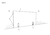
- Fig. 2 shows a Attikaplatte 3 in a rear view, in which two recesses 11 can be seen, which are adapted to each at least partially receive an angular component.
- a rear view is understood to mean a perspective in which a viewer is outside a zone bounded by the attic 2 in front of the attic 2.
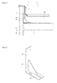
- Fig. 3 shows a schematic sectional view of the first embodiment according to Fig. 2 in the assembled state (final state).
- the angle component has therein two mutually orthogonal legs, namely a horizontal leg 4a and a vertical leg 4b.
- the horizontal leg 4a is screwed to a raw ceiling 9, which is part of the ceiling element 5a.
- the vertical leg 4b is bolted to the Attikaplatte 3, through which the mandrel 6 projects into a gradient concrete 10, which is applied (after mounting the Attikaplatte 3) on the blanket 9 and the mandrel 6 completely encloses, whereby the angular component after curing of the gradient concrete 10 is additionally stabilized.
- the gradient concrete 10 forms a part of the ceiling element 5a.
- the recess 11 in the Attikaplatte 3 is designed so that the vertical leg 4b of the angular component can be completely absorbed therein.
- a thermally insulating insulating layer 13a is attached, which is completed by a facade area 14.
- At a lower end portion 15 opposite, facing away from the base 5 upper end portion 16 at least one cover plate 17 is attached, which extends from the Attikaplatte 3 on the insulating layer 13a to the facade area 14 and limits the attic.
- the Attikaplatte 3 has a water-repellent insulating layer 18 on an inner surface 20 facing the ceiling element 5a.
- This may be, for example, a bitumen-containing insulating layer 18, which can be applied by scarfing.
- the insulating layer 18 extends, for example, completely over a roof surface on which an insulating layer 13b as well as, for example, a gravel layer 21 may be applied.
- the Attikaplatte 3 additionally has a blending 19, which is executed in several parts in the embodiment shown and extends from the inner side 20 of the Attikaplatte 3 on the cover plate 17 up to the facade area 14.
- FIG. 4 A perspective view of an angular component according to Fig. 2 and 3 is in Fig. 4 recognizable.
- the mandrel 6 is centrally mounted in a lower portion of the vertical leg 4b and extends parallel to the horizontal leg 4a.
- the aspect ratios, the angles between the individual elements (legs 4a, 4b, mandrel 6) and the positioning relative to each other as well as the dimensioning of the angular component are not limited to the embodiment shown and can be modified depending on circumstances and requirements.
- Fig. 5 shows a sectional view of a second embodiment of the mounting structure according to the invention for a building 1 with a parapet 2.
- the running as an angular component fastener 4 has no as in Fig. 2 to 3 Instead, shown mandrel 6, but instead has a diagonal strut 22, with the horizontal leg 4a is additionally connected to the vertical leg 4b.
- the horizontal leg 4a is screwed to the raw ceiling 9, wherein the screw must be designed to be particularly resilient due to the omission of the stabilizing mandrel 6.
- the vertical leg 4b also has a screw connection with the Attikaplatte 3.
- the oblique strut 22 serves to stabilize the legs 4a and 4b and counteracts bending or twisting thereof.
- the diagonal strut 22 pour in concrete or embed them in it. Rather, the insulating layer 13b can be applied directly to the raw ceiling 9.
- the recess 11 for receiving the angular component is designed so that the oblique strut 22 is guided and received within a (not shown) slot in the Attikaplatte 3.
- FIG. 6 A perspective view of the angular component according to Fig. 5 is in Fig. 6 shown.
- the legs 4a and 4b are oriented orthogonally to one another and the oblique strut 22 is arranged in the center in the contact region thereof.
- the number of holes is due to the omission of the mandrel 6 is generally higher than in an angular component according to the first embodiment, whereby a particularly stable screwing of the angular component can be done.
- the holes in the horizontal leg 4a can be executed in all embodiments shown as slots to allow readjustment of the Attikaplatten 3 and the angle components in a simple manner.
- the angular component may have both a diagonal strut 22 and a mandrel 6.
- any hybrid forms of the aforementioned embodiments are conceivable.
- Fig. 7 shows a sectional view of a third embodiment of the mounting structure according to the invention for a building 1 with a parapet 2.
- the base member 23 has a base surface 24 and is connectable to the Attikaplatte 3 at the lower end portion 15 on an inner side 20 of the Attikaplatte 3 opposite the fastening element 4. In the connected state, the base surface 24 expands a base 5 facing standing surface 25 of the Attikaplatte 3 plan.
- the fastening element 4 is designed as a fastening plate 4c with a mandrel 6 which is adapted to project into the ceiling element 5a, in particular into the raw ceiling 9.
- the mounting plate 4c is completely received in a recess 11 located within the Attikaplatte 3 and bolted to the Attikaplatte 3.
- the mounting plate 4c also has (as in Fig. 8 visible) in each case a bore, which is arranged above or below the mandrel 6.
- the mounting plate 4c is vertically aligned and arranged such that a threaded connection through the standing surface facing Bore (ie those below the mandrel 6) extends into the opposite base element 23, whereby the base member 23 is fixed to the Attikaplatte 3.
- the base element 23 and the Attikaplatte 3 are additionally glued together, whereby the connection of base element 23 and Attikaplatte 3 can be realized permanently and very stable.
- the Attikaplatte 3 and the base member 23 can be quickly fixed in a simple manner to the masonry 5b by an adhesive bond.
- the longitudinal extent of the base element 23 is in accordance with that of the Attikaplatte 3, wherein the base member 23 is offset with respect to the Attikaplatte 3 by a predetermined length (for example, 5cm, 10cm, 15cm, or 20cm).
- Attikaplatten 3 can be particularly easy to arrange next to each other, since base elements 23 adjacent Attikaplatten 3 contact each other or the Attikaplatten 3 can be aligned with the base elements 23 aligned. A resulting overlap can be used for additional stabilization of attic panels 3 fastened next to each other.
- the raw ceiling 9 is not sufficient during this assembly step to the mandrel 6 zoom. Rather, the gap between the mandrel 6 and the raw ceiling 9 is subsequently filled with a filling material, for example, poured with concrete, wherein the mandrel 6 is surrounded by the filler material form fit.
- a filling material for example, poured with concrete
- the base element 23 may also be surrounded by the concrete in a form-fitting manner.
- the stabilizing effect of the mandrel 6 occurs as soon as the filling material has hardened.
- In this embodiment can generally be dispensed with the attachment of a gradient concrete.
- Fig. 8 is the mounting plate 4c according to Fig. 7 recognizable in a perspective view.
- the mandrel 6 protrudes vertically from the center.
- Velvet mentioned embodiments of the invention have the significant advantages that they are easy to assemble, have high stability, the components used are easy to prepare and transport and require a low cost of materials.
- the space requirement of the embodiments according to the invention is extremely low, which increases the proportion of usable space of such a narrowed area compared to conventional solutions.
- the good thermal insulating properties of the Attika plate 3 make it possible to dispense with additional thermal separation elements between the Attica 2 and the Attikaplatte 3 and the base 5, whereby a solid design of a mounting structure for a building 1 with a parapet 2 is given in a surprising manner.
Landscapes
- Engineering & Computer Science (AREA)
- Architecture (AREA)
- Civil Engineering (AREA)
- Structural Engineering (AREA)
- Joining Of Building Structures In Genera (AREA)
- Finishing Walls (AREA)
- Building Environments (AREA)
- Roof Covering Using Slabs Or Stiff Sheets (AREA)
Priority Applications (1)
| Application Number | Priority Date | Filing Date | Title |
|---|---|---|---|
| EP16201134.0A EP3156554B1 (fr) | 2012-10-24 | 2013-10-11 | Structure de fixation pour un bâtiment doté d'un acrotère |
Applications Claiming Priority (1)
| Application Number | Priority Date | Filing Date | Title |
|---|---|---|---|
| ATA50475/2012A AT512918B1 (de) | 2012-10-24 | 2012-10-24 | Befestigungsaufbau für ein Gebäude mit einer Attika |
Related Child Applications (1)
| Application Number | Title | Priority Date | Filing Date |
|---|---|---|---|
| EP16201134.0A Division EP3156554B1 (fr) | 2012-10-24 | 2013-10-11 | Structure de fixation pour un bâtiment doté d'un acrotère |
Publications (3)
| Publication Number | Publication Date |
|---|---|
| EP2725164A2 true EP2725164A2 (fr) | 2014-04-30 |
| EP2725164A3 EP2725164A3 (fr) | 2014-05-21 |
| EP2725164B1 EP2725164B1 (fr) | 2016-11-30 |
Family
ID=49354496
Family Applications (2)
| Application Number | Title | Priority Date | Filing Date |
|---|---|---|---|
| EP16201134.0A Active EP3156554B1 (fr) | 2012-10-24 | 2013-10-11 | Structure de fixation pour un bâtiment doté d'un acrotère |
| EP13188220.1A Active EP2725164B1 (fr) | 2012-10-24 | 2013-10-11 | Kit de construction pour une structure de fixation pour un bâtiment doté d'un acrotère |
Family Applications Before (1)
| Application Number | Title | Priority Date | Filing Date |
|---|---|---|---|
| EP16201134.0A Active EP3156554B1 (fr) | 2012-10-24 | 2013-10-11 | Structure de fixation pour un bâtiment doté d'un acrotère |
Country Status (2)
| Country | Link |
|---|---|
| EP (2) | EP3156554B1 (fr) |
| AT (1) | AT512918B1 (fr) |
Cited By (3)
| Publication number | Priority date | Publication date | Assignee | Title |
|---|---|---|---|---|
| AT15128U1 (de) * | 2015-08-20 | 2017-01-15 | Austyrol Dämmstoffe Ges M B H | Attika für ein durch Dämmplatten wärmegedämmtes Gebäude |
| AT522720A1 (de) * | 2019-07-02 | 2021-01-15 | Alexander Schoerflinger | Attikasystem für eine Flachdachabschalung |
| AT522719A3 (de) * | 2019-07-02 | 2021-12-15 | Alexander Schoerflinger | Attikasystem für eine Flachdachabschalung |
Families Citing this family (4)
| Publication number | Priority date | Publication date | Assignee | Title |
|---|---|---|---|---|
| EP3175059A1 (fr) | 2014-08-01 | 2017-06-07 | Sebastian Hilscher | Lot d'éléments pour ensemble de balustrade d'un bâtiment |
| AT522149B1 (de) | 2019-03-13 | 2020-09-15 | Hilscher Sebastian | Bausatz für einen brüstungsaufbau an einem gebäude |
| AT525083B1 (de) * | 2021-11-17 | 2022-12-15 | Hilscher Sebastian | Bausatz für einen Attikaaufbau an einem Gebäude |
| US12618240B2 (en) * | 2023-02-17 | 2026-05-05 | KDScott Companies LLC | Roof façade assembly and sealable bracket assembly for mounting the same |
Family Cites Families (6)
| Publication number | Priority date | Publication date | Assignee | Title |
|---|---|---|---|---|
| CH538029A (de) * | 1971-05-04 | 1973-06-15 | Amsler Max | Vorrichtung zur Bildung des Randabschlusses eines Flachdaches |
| DE2164118A1 (de) * | 1971-12-23 | 1973-07-05 | Dynamit Nobel Ag | Dachrandblenden fuer flachdaecher und zugehoerige befestigungsvorrichtungen |
| US3738068A (en) * | 1972-10-31 | 1973-06-12 | Miscellaneous Mfg Corp | Conjoint facia and water dam |
| US6088992A (en) * | 1997-04-15 | 2000-07-18 | Loadmaster Systems, Inc. | Roof deck termination structure |
| ATE389759T1 (de) * | 2005-06-22 | 2008-04-15 | Ulrich Maag | Dachrandeement |
| AT506993B1 (de) | 2008-09-09 | 2010-01-15 | Martin Freund | Wärmebrückenfreie attika |
-
2012
- 2012-10-24 AT ATA50475/2012A patent/AT512918B1/de active
-
2013
- 2013-10-11 EP EP16201134.0A patent/EP3156554B1/fr active Active
- 2013-10-11 EP EP13188220.1A patent/EP2725164B1/fr active Active
Cited By (5)
| Publication number | Priority date | Publication date | Assignee | Title |
|---|---|---|---|---|
| AT15128U1 (de) * | 2015-08-20 | 2017-01-15 | Austyrol Dämmstoffe Ges M B H | Attika für ein durch Dämmplatten wärmegedämmtes Gebäude |
| AT522720A1 (de) * | 2019-07-02 | 2021-01-15 | Alexander Schoerflinger | Attikasystem für eine Flachdachabschalung |
| AT522720B1 (de) * | 2019-07-02 | 2021-06-15 | Alexander Schoerflinger | Attikasystem für eine Flachdachabschalung |
| AT522719A3 (de) * | 2019-07-02 | 2021-12-15 | Alexander Schoerflinger | Attikasystem für eine Flachdachabschalung |
| AT522719B1 (de) * | 2019-07-02 | 2022-02-15 | Alexander Schoerflinger | Attikasystem für eine Flachdachabschalung |
Also Published As
| Publication number | Publication date |
|---|---|
| EP3156554A1 (fr) | 2017-04-19 |
| EP2725164B1 (fr) | 2016-11-30 |
| EP2725164A3 (fr) | 2014-05-21 |
| AT512918B1 (de) | 2013-12-15 |
| AT512918A4 (de) | 2013-12-15 |
| EP3156554B1 (fr) | 2020-03-25 |
Similar Documents
| Publication | Publication Date | Title |
|---|---|---|
| EP2725164B1 (fr) | Kit de construction pour une structure de fixation pour un bâtiment doté d'un acrotère | |
| EP3269889A1 (fr) | Système de connexion | |
| DE202004004965U1 (de) | Schalungselement | |
| EP3175059A1 (fr) | Lot d'éléments pour ensemble de balustrade d'un bâtiment | |
| DE202005011486U1 (de) | Gebäudewand aus industriell vorgefertigten, mehrlagigen Fertigwandteilen | |
| DE19920032A1 (de) | Herstellungs- und Montagesystem für Fertigteile von Gebäuden | |
| EP0898026A2 (fr) | Maison préfabriquée | |
| DE19537139A1 (de) | Vorgefertigtes Massivhaus in Modulbauweise | |
| DE102016103982B4 (de) | Schalungselement | |
| DE102005028697B4 (de) | System zum Erstellen einer Gebäudewand | |
| DE102016103981B4 (de) | Schalungselement | |
| EP3832045B1 (fr) | Procédé de fabrication d'un raccordement d'un élément composite bois-béton plan avec au moins une partie d'une structure en bois | |
| DE10230963A1 (de) | Verfahren zur Herstellung einer tragenden Wand und ein entsprechendes Bauelement zur Durchführung des Verfahrens | |
| DE102012007700B4 (de) | Stahlbetondecke mit mindestens einer darauf befestigten Fußpfette | |
| EP3024992B1 (fr) | Système de fixation d'éléments isolants | |
| AT524906B1 (de) | Bausatz für ein Schalungselement und Schalungselement | |
| DE102004003366B4 (de) | Verfahren zum Herstellen eines Einfamilien-oder Mehrfamilienhauses, Betonfertigteil-Trogplatte für eine Gebäudedecke sowie Fertighaus | |
| DE102004024316A1 (de) | Mehrteiliger Verbinder zur Befestigung eines Wandelements auf einem Betonuntergrund und Verbindungsanordnung mit einem derartigen Verbinder | |
| DE102016219222A1 (de) | Gebäudewand mit wärmegedämmter Fassadenverkleidung | |
| DE202024106524U1 (de) | Attikavorrichtung, Attikasystem mit einer Attikavorrichtung und Flachdach mit einem Attikasystem | |
| EP3130718A1 (fr) | Élement composite de construction | |
| DE20318689U1 (de) | Holzbauelement | |
| EP4737662A1 (fr) | Ensembles de liaison par poussée pour élément préfabriqué composite | |
| AT517855A4 (de) | Bausatz für einen Brüstungsaufbau | |
| WO2023062483A1 (fr) | Système de construction |
Legal Events
| Date | Code | Title | Description |
|---|---|---|---|
| PUAL | Search report despatched |
Free format text: ORIGINAL CODE: 0009013 |
|
| PUAI | Public reference made under article 153(3) epc to a published international application that has entered the european phase |
Free format text: ORIGINAL CODE: 0009012 |
|
| 17P | Request for examination filed |
Effective date: 20131011 |
|
| AK | Designated contracting states |
Kind code of ref document: A2 Designated state(s): AL AT BE BG CH CY CZ DE DK EE ES FI FR GB GR HR HU IE IS IT LI LT LU LV MC MK MT NL NO PL PT RO RS SE SI SK SM TR |
|
| AX | Request for extension of the european patent |
Extension state: BA ME |
|
| AK | Designated contracting states |
Kind code of ref document: A3 Designated state(s): AL AT BE BG CH CY CZ DE DK EE ES FI FR GB GR HR HU IE IS IT LI LT LU LV MC MK MT NL NO PL PT RO RS SE SI SK SM TR |
|
| AX | Request for extension of the european patent |
Extension state: BA ME |
|
| RIC1 | Information provided on ipc code assigned before grant |
Ipc: E04D 13/14 20060101AFI20140411BHEP Ipc: E04D 13/155 20060101ALI20140411BHEP |
|
| 17P | Request for examination filed |
Effective date: 20141118 |
|
| RBV | Designated contracting states (corrected) |
Designated state(s): AL AT BE BG CH CY CZ DE DK EE ES FI FR GB GR HR HU IE IS IT LI LT LU LV MC MK MT NL NO PL PT RO RS SE SI SK SM TR |
|
| 17Q | First examination report despatched |
Effective date: 20150916 |
|
| GRAP | Despatch of communication of intention to grant a patent |
Free format text: ORIGINAL CODE: EPIDOSNIGR1 |
|
| INTG | Intention to grant announced |
Effective date: 20160518 |
|
| GRAS | Grant fee paid |
Free format text: ORIGINAL CODE: EPIDOSNIGR3 |
|
| GRAA | (expected) grant |
Free format text: ORIGINAL CODE: 0009210 |
|
| AK | Designated contracting states |
Kind code of ref document: B1 Designated state(s): AL AT BE BG CH CY CZ DE DK EE ES FI FR GB GR HR HU IE IS IT LI LT LU LV MC MK MT NL NO PL PT RO RS SE SI SK SM TR |
|
| REG | Reference to a national code |
Ref country code: CH Ref legal event code: EP Ref country code: GB Ref legal event code: FG4D Free format text: NOT ENGLISH |
|
| REG | Reference to a national code |
Ref country code: AT Ref legal event code: REF Ref document number: 849954 Country of ref document: AT Kind code of ref document: T Effective date: 20161215 |
|
| REG | Reference to a national code |
Ref country code: IE Ref legal event code: FG4D Free format text: LANGUAGE OF EP DOCUMENT: GERMAN |
|
| REG | Reference to a national code |
Ref country code: DE Ref legal event code: R096 Ref document number: 502013005538 Country of ref document: DE |
|
| PG25 | Lapsed in a contracting state [announced via postgrant information from national office to epo] |
Ref country code: LV Free format text: LAPSE BECAUSE OF FAILURE TO SUBMIT A TRANSLATION OF THE DESCRIPTION OR TO PAY THE FEE WITHIN THE PRESCRIBED TIME-LIMIT Effective date: 20161130 |
|
| REG | Reference to a national code |
Ref country code: CH Ref legal event code: NV Representative=s name: RENTSCH PARTNER AG, CH |
|
| REG | Reference to a national code |
Ref country code: LT Ref legal event code: MG4D |
|
| REG | Reference to a national code |
Ref country code: NL Ref legal event code: MP Effective date: 20161130 |
|
| PG25 | Lapsed in a contracting state [announced via postgrant information from national office to epo] |
Ref country code: GR Free format text: LAPSE BECAUSE OF FAILURE TO SUBMIT A TRANSLATION OF THE DESCRIPTION OR TO PAY THE FEE WITHIN THE PRESCRIBED TIME-LIMIT Effective date: 20170301 Ref country code: SE Free format text: LAPSE BECAUSE OF FAILURE TO SUBMIT A TRANSLATION OF THE DESCRIPTION OR TO PAY THE FEE WITHIN THE PRESCRIBED TIME-LIMIT Effective date: 20161130 Ref country code: NO Free format text: LAPSE BECAUSE OF FAILURE TO SUBMIT A TRANSLATION OF THE DESCRIPTION OR TO PAY THE FEE WITHIN THE PRESCRIBED TIME-LIMIT Effective date: 20170228 Ref country code: LT Free format text: LAPSE BECAUSE OF FAILURE TO SUBMIT A TRANSLATION OF THE DESCRIPTION OR TO PAY THE FEE WITHIN THE PRESCRIBED TIME-LIMIT Effective date: 20161130 |
|
| PG25 | Lapsed in a contracting state [announced via postgrant information from national office to epo] |
Ref country code: ES Free format text: LAPSE BECAUSE OF FAILURE TO SUBMIT A TRANSLATION OF THE DESCRIPTION OR TO PAY THE FEE WITHIN THE PRESCRIBED TIME-LIMIT Effective date: 20161130 Ref country code: PT Free format text: LAPSE BECAUSE OF FAILURE TO SUBMIT A TRANSLATION OF THE DESCRIPTION OR TO PAY THE FEE WITHIN THE PRESCRIBED TIME-LIMIT Effective date: 20170330 Ref country code: PL Free format text: LAPSE BECAUSE OF FAILURE TO SUBMIT A TRANSLATION OF THE DESCRIPTION OR TO PAY THE FEE WITHIN THE PRESCRIBED TIME-LIMIT Effective date: 20161130 Ref country code: HR Free format text: LAPSE BECAUSE OF FAILURE TO SUBMIT A TRANSLATION OF THE DESCRIPTION OR TO PAY THE FEE WITHIN THE PRESCRIBED TIME-LIMIT Effective date: 20161130 Ref country code: FI Free format text: LAPSE BECAUSE OF FAILURE TO SUBMIT A TRANSLATION OF THE DESCRIPTION OR TO PAY THE FEE WITHIN THE PRESCRIBED TIME-LIMIT Effective date: 20161130 Ref country code: RS Free format text: LAPSE BECAUSE OF FAILURE TO SUBMIT A TRANSLATION OF THE DESCRIPTION OR TO PAY THE FEE WITHIN THE PRESCRIBED TIME-LIMIT Effective date: 20161130 |
|
| PG25 | Lapsed in a contracting state [announced via postgrant information from national office to epo] |
Ref country code: NL Free format text: LAPSE BECAUSE OF FAILURE TO SUBMIT A TRANSLATION OF THE DESCRIPTION OR TO PAY THE FEE WITHIN THE PRESCRIBED TIME-LIMIT Effective date: 20161130 |
|
| PG25 | Lapsed in a contracting state [announced via postgrant information from national office to epo] |
Ref country code: CZ Free format text: LAPSE BECAUSE OF FAILURE TO SUBMIT A TRANSLATION OF THE DESCRIPTION OR TO PAY THE FEE WITHIN THE PRESCRIBED TIME-LIMIT Effective date: 20161130 Ref country code: EE Free format text: LAPSE BECAUSE OF FAILURE TO SUBMIT A TRANSLATION OF THE DESCRIPTION OR TO PAY THE FEE WITHIN THE PRESCRIBED TIME-LIMIT Effective date: 20161130 Ref country code: SK Free format text: LAPSE BECAUSE OF FAILURE TO SUBMIT A TRANSLATION OF THE DESCRIPTION OR TO PAY THE FEE WITHIN THE PRESCRIBED TIME-LIMIT Effective date: 20161130 Ref country code: RO Free format text: LAPSE BECAUSE OF FAILURE TO SUBMIT A TRANSLATION OF THE DESCRIPTION OR TO PAY THE FEE WITHIN THE PRESCRIBED TIME-LIMIT Effective date: 20161130 Ref country code: DK Free format text: LAPSE BECAUSE OF FAILURE TO SUBMIT A TRANSLATION OF THE DESCRIPTION OR TO PAY THE FEE WITHIN THE PRESCRIBED TIME-LIMIT Effective date: 20161130 |
|
| PG25 | Lapsed in a contracting state [announced via postgrant information from national office to epo] |
Ref country code: IT Free format text: LAPSE BECAUSE OF FAILURE TO SUBMIT A TRANSLATION OF THE DESCRIPTION OR TO PAY THE FEE WITHIN THE PRESCRIBED TIME-LIMIT Effective date: 20161130 Ref country code: BG Free format text: LAPSE BECAUSE OF FAILURE TO SUBMIT A TRANSLATION OF THE DESCRIPTION OR TO PAY THE FEE WITHIN THE PRESCRIBED TIME-LIMIT Effective date: 20170228 Ref country code: SM Free format text: LAPSE BECAUSE OF FAILURE TO SUBMIT A TRANSLATION OF THE DESCRIPTION OR TO PAY THE FEE WITHIN THE PRESCRIBED TIME-LIMIT Effective date: 20161130 |
|
| REG | Reference to a national code |
Ref country code: DE Ref legal event code: R097 Ref document number: 502013005538 Country of ref document: DE |
|
| REG | Reference to a national code |
Ref country code: CH Ref legal event code: PCAR Free format text: NEW ADDRESS: BELLERIVESTRASSE 203 POSTFACH, 8034 ZUERICH (CH) |
|
| PLBE | No opposition filed within time limit |
Free format text: ORIGINAL CODE: 0009261 |
|
| STAA | Information on the status of an ep patent application or granted ep patent |
Free format text: STATUS: NO OPPOSITION FILED WITHIN TIME LIMIT |
|
| 26N | No opposition filed |
Effective date: 20170831 |
|
| PG25 | Lapsed in a contracting state [announced via postgrant information from national office to epo] |
Ref country code: SI Free format text: LAPSE BECAUSE OF FAILURE TO SUBMIT A TRANSLATION OF THE DESCRIPTION OR TO PAY THE FEE WITHIN THE PRESCRIBED TIME-LIMIT Effective date: 20161130 |
|
| PGFP | Annual fee paid to national office [announced via postgrant information from national office to epo] |
Ref country code: CH Payment date: 20171019 Year of fee payment: 5 |
|
| PG25 | Lapsed in a contracting state [announced via postgrant information from national office to epo] |
Ref country code: MC Free format text: LAPSE BECAUSE OF FAILURE TO SUBMIT A TRANSLATION OF THE DESCRIPTION OR TO PAY THE FEE WITHIN THE PRESCRIBED TIME-LIMIT Effective date: 20161130 |
|
| GBPC | Gb: european patent ceased through non-payment of renewal fee |
Effective date: 20171011 |
|
| REG | Reference to a national code |
Ref country code: IE Ref legal event code: MM4A |
|
| REG | Reference to a national code |
Ref country code: FR Ref legal event code: ST Effective date: 20180629 |
|
| PG25 | Lapsed in a contracting state [announced via postgrant information from national office to epo] |
Ref country code: GB Free format text: LAPSE BECAUSE OF NON-PAYMENT OF DUE FEES Effective date: 20171011 Ref country code: LU Free format text: LAPSE BECAUSE OF NON-PAYMENT OF DUE FEES Effective date: 20171011 |
|
| REG | Reference to a national code |
Ref country code: BE Ref legal event code: MM Effective date: 20171031 |
|
| PG25 | Lapsed in a contracting state [announced via postgrant information from national office to epo] |
Ref country code: FR Free format text: LAPSE BECAUSE OF NON-PAYMENT OF DUE FEES Effective date: 20171031 Ref country code: BE Free format text: LAPSE BECAUSE OF NON-PAYMENT OF DUE FEES Effective date: 20171031 |
|
| PG25 | Lapsed in a contracting state [announced via postgrant information from national office to epo] |
Ref country code: MT Free format text: LAPSE BECAUSE OF FAILURE TO SUBMIT A TRANSLATION OF THE DESCRIPTION OR TO PAY THE FEE WITHIN THE PRESCRIBED TIME-LIMIT Effective date: 20161130 |
|
| PG25 | Lapsed in a contracting state [announced via postgrant information from national office to epo] |
Ref country code: IE Free format text: LAPSE BECAUSE OF NON-PAYMENT OF DUE FEES Effective date: 20171011 |
|
| REG | Reference to a national code |
Ref country code: CH Ref legal event code: PL |
|
| PG25 | Lapsed in a contracting state [announced via postgrant information from national office to epo] |
Ref country code: HU Free format text: LAPSE BECAUSE OF FAILURE TO SUBMIT A TRANSLATION OF THE DESCRIPTION OR TO PAY THE FEE WITHIN THE PRESCRIBED TIME-LIMIT; INVALID AB INITIO Effective date: 20131011 |
|
| PG25 | Lapsed in a contracting state [announced via postgrant information from national office to epo] |
Ref country code: CH Free format text: LAPSE BECAUSE OF NON-PAYMENT OF DUE FEES Effective date: 20181031 Ref country code: LI Free format text: LAPSE BECAUSE OF NON-PAYMENT OF DUE FEES Effective date: 20181031 |
|
| PG25 | Lapsed in a contracting state [announced via postgrant information from national office to epo] |
Ref country code: CY Free format text: LAPSE BECAUSE OF NON-PAYMENT OF DUE FEES Effective date: 20161130 |
|
| PG25 | Lapsed in a contracting state [announced via postgrant information from national office to epo] |
Ref country code: MK Free format text: LAPSE BECAUSE OF FAILURE TO SUBMIT A TRANSLATION OF THE DESCRIPTION OR TO PAY THE FEE WITHIN THE PRESCRIBED TIME-LIMIT Effective date: 20161130 |
|
| REG | Reference to a national code |
Ref country code: AT Ref legal event code: MM01 Ref document number: 849954 Country of ref document: AT Kind code of ref document: T Effective date: 20181011 |
|
| PG25 | Lapsed in a contracting state [announced via postgrant information from national office to epo] |
Ref country code: AT Free format text: LAPSE BECAUSE OF NON-PAYMENT OF DUE FEES Effective date: 20181011 |
|
| PG25 | Lapsed in a contracting state [announced via postgrant information from national office to epo] |
Ref country code: TR Free format text: LAPSE BECAUSE OF FAILURE TO SUBMIT A TRANSLATION OF THE DESCRIPTION OR TO PAY THE FEE WITHIN THE PRESCRIBED TIME-LIMIT Effective date: 20161130 |
|
| PG25 | Lapsed in a contracting state [announced via postgrant information from national office to epo] |
Ref country code: AL Free format text: LAPSE BECAUSE OF FAILURE TO SUBMIT A TRANSLATION OF THE DESCRIPTION OR TO PAY THE FEE WITHIN THE PRESCRIBED TIME-LIMIT Effective date: 20161130 Ref country code: IS Free format text: LAPSE BECAUSE OF FAILURE TO SUBMIT A TRANSLATION OF THE DESCRIPTION OR TO PAY THE FEE WITHIN THE PRESCRIBED TIME-LIMIT Effective date: 20170330 |
|
| P01 | Opt-out of the competence of the unified patent court (upc) registered |
Effective date: 20230524 |
|
| PGFP | Annual fee paid to national office [announced via postgrant information from national office to epo] |
Ref country code: DE Payment date: 20251021 Year of fee payment: 13 |