EP2141105A1 - Spleisskopf, spleissvorrichtung und spleissverfahren - Google Patents
Spleisskopf, spleissvorrichtung und spleissverfahren Download PDFInfo
- Publication number
- EP2141105A1 EP2141105A1 EP08738730A EP08738730A EP2141105A1 EP 2141105 A1 EP2141105 A1 EP 2141105A1 EP 08738730 A EP08738730 A EP 08738730A EP 08738730 A EP08738730 A EP 08738730A EP 2141105 A1 EP2141105 A1 EP 2141105A1
- Authority
- EP
- European Patent Office
- Prior art keywords
- yarn
- yarns
- untwisting
- nozzle hole
- accommodating space
- Prior art date
- Legal status (The legal status is an assumption and is not a legal conclusion. Google has not performed a legal analysis and makes no representation as to the accuracy of the status listed.)
- Granted
Links
Images




Classifications
-
- B—PERFORMING OPERATIONS; TRANSPORTING
- B65—CONVEYING; PACKING; STORING; HANDLING THIN OR FILAMENTARY MATERIAL
- B65H—HANDLING THIN OR FILAMENTARY MATERIAL, e.g. SHEETS, WEBS, CABLES
- B65H69/00—Methods of, or devices for, interconnecting successive lengths of material; Knot-tying devices ;Control of the correct working of the interconnecting device
- B65H69/06—Methods of, or devices for, interconnecting successive lengths of material; Knot-tying devices ;Control of the correct working of the interconnecting device by splicing
- B65H69/061—Methods of, or devices for, interconnecting successive lengths of material; Knot-tying devices ;Control of the correct working of the interconnecting device by splicing using pneumatic means
-
- B—PERFORMING OPERATIONS; TRANSPORTING
- B65—CONVEYING; PACKING; STORING; HANDLING THIN OR FILAMENTARY MATERIAL
- B65H—HANDLING THIN OR FILAMENTARY MATERIAL, e.g. SHEETS, WEBS, CABLES
- B65H69/00—Methods of, or devices for, interconnecting successive lengths of material; Knot-tying devices ;Control of the correct working of the interconnecting device
- B65H69/06—Methods of, or devices for, interconnecting successive lengths of material; Knot-tying devices ;Control of the correct working of the interconnecting device by splicing
-
- B—PERFORMING OPERATIONS; TRANSPORTING
- B65—CONVEYING; PACKING; STORING; HANDLING THIN OR FILAMENTARY MATERIAL
- B65H—HANDLING THIN OR FILAMENTARY MATERIAL, e.g. SHEETS, WEBS, CABLES
- B65H69/00—Methods of, or devices for, interconnecting successive lengths of material; Knot-tying devices ;Control of the correct working of the interconnecting device
- B65H69/04—Methods of, or devices for, interconnecting successive lengths of material; Knot-tying devices ;Control of the correct working of the interconnecting device by knotting
-
- B—PERFORMING OPERATIONS; TRANSPORTING
- B65—CONVEYING; PACKING; STORING; HANDLING THIN OR FILAMENTARY MATERIAL
- B65H—HANDLING THIN OR FILAMENTARY MATERIAL, e.g. SHEETS, WEBS, CABLES
- B65H69/00—Methods of, or devices for, interconnecting successive lengths of material; Knot-tying devices ;Control of the correct working of the interconnecting device
- B65H69/06—Methods of, or devices for, interconnecting successive lengths of material; Knot-tying devices ;Control of the correct working of the interconnecting device by splicing
- B65H69/061—Methods of, or devices for, interconnecting successive lengths of material; Knot-tying devices ;Control of the correct working of the interconnecting device by splicing using pneumatic means
- B65H69/063—Preparation of the yarn ends
-
- D—TEXTILES; PAPER
- D01—NATURAL OR MAN-MADE THREADS OR FIBRES; SPINNING
- D01H—SPINNING OR TWISTING
- D01H15/00—Piecing arrangements ; Automatic end-finding, e.g. by suction and reverse package rotation; Devices for temporarily storing yarn during piecing
-
- B—PERFORMING OPERATIONS; TRANSPORTING
- B65—CONVEYING; PACKING; STORING; HANDLING THIN OR FILAMENTARY MATERIAL
- B65H—HANDLING THIN OR FILAMENTARY MATERIAL, e.g. SHEETS, WEBS, CABLES
- B65H2701/00—Handled material; Storage means
- B65H2701/30—Handled filamentary material
- B65H2701/31—Textiles threads or artificial strands of filaments
Definitions
- the present invention relates to a splicing head used in a splicing device that pieces a plurality of yarns into each other, a splicing device including the splicing head, and a splicing method.
- a conventional splicing head disclosed in Japanese Unexamined Patent Publication JP-A 2006-52485 includes a first nozzle hole that injects a compressed fluid substantially perpendicularly into a yarn-accommodating space, and a second nozzle hole that injects a compressed fluid in a direction inclined from the base end portions toward the front end portions of yarns that are inserted into the yarn-accommodating space.
- the compressed fluids injected from the first nozzle hole and the second nozzle hole respectively proceed in directions that intersect the central axis of the yarn-accommodating space.
- the compressed fluids injected from the respective nozzle holes proceed toward the central axis of the yarn-accommodating space.
- the amount of untwisted yarn accommodated in the yarn-accommodating space is small.
- the intertwining of a plurality of yarns may be insufficient even when the plurality of yarns collide against each other.
- the amount untwisted in the above-described conventional splicing head is small because each of the two-ply yarns is twisted, and thus, sufficient piecing cannot be performed. Accordingly, there is a problem in that the strength of such a pieced portion is lowered.
- the intertwining of such two-ply yarns is loose, and thus, there is a problem in that the strength of such a pieced portion is further lowered.
- a splicing device including the above-described splicing head and a splicing method also suffer these problems in a similar manner.
- the invention is directed to a splicing head used in a splicing device that pieces a plurality of overlapped yarns into each other by injecting a compressed fluid toward the plurality of yarns under the state that front end portions of the plurality of yarns overlap each other in a same direction, comprising:
- the untwisting-nozzle hole extends closer to one side in one direction of the central axis, toward the central axis in a direction perpendicular to the central axis, and is inclined with respect to the central axis.
- a first untwisting direction in which a first untwisting-nozzle hole extends toward the yarn-accommodating space and a second untwisting direction in which a second untwisting-nozzle hole extends toward the yarn-accommodating space are opposite each other about the central axis.
- the invention is directed to a splicing device, comprising:
- the invention is directed to a splicing method for piecing a plurality of yarns into each other using a splicing head including a yarn-accommodating space that can accommodate a plurality of overlapped yarns and that extends along a predetermined central axis, an untwisting-nozzle hole that brings the yarn-accommodating space in communication with an outside space and that extends in a torsional direction, which is torsional about the central axis, and a piecing-nozzle hole that brings the yarn-accommodating space in communication with an outside space and that extends in an intersecting direction, which intersects the central axis, comprising:
- the untwisting step is necessary is selectively switched according to at least one of a type of yarn-twisting and a number of a plurality of yarns that are to be pieced into each other.
- a direction for injecting a compressed fluid is switched so that the compressed fluid rotates in an opposite direction to a direction in which two-ply yarns are twisted.
- type of yarn-twisting refers to types, such as single yarn, two-ply yarn, or three-ply yarn obtained by intertwining three single yarns.
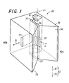
- Fig. 1 is an enlarged perspective view showing a splicing head 20 according to an embodiment of the invention.
- Fig. 2 is a front view showing the splicing head 20.
- Fig. 3 is a plan view showing the splicing head 20.
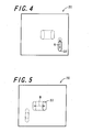
- Fig. 4 is a right side view of the splicing head 20.
- Fig. 5 is a left side view of the splicing head 20.
- the splicing head 20 is a nozzle hole formation member that is provided in a splicing device 30 and that has nozzle holes through which compressed air, which is a compressed fluid, passes.
- the splicing device 30 is an apparatus that pieces and joins a plurality of knitting yarns accommodated in a yarn-accommodating space 31 of the splicing head 20 by injecting a compressed fluid into the yarn-accommodating space 31.
- the splicing device 30 pieces two two-ply yarns into each other.
- the splicing head 20 is formed in the shape of a column that extends in a predetermined axial direction Z, and cross-sections perpendicular to the axial direction Z have substantially the same shape.
- the splicing head 20 has a yarn-accommodating space 31, an untwisting-nozzle hole 32, a piecing-nozzle hole 33, an entrance space-forming portion 24, and a communicating passage 35.
- the yarn-accommodating space 31 is formed in the shape of a tube that surrounds a central axis L1 extending in a predetermined direction and that is open on both sides of the central axis L1 in the axial direction Z.
- the yarn-accommodating space 31 is formed so as to be capable of loosely accommodating two two-ply yarns extending along the central axis L1 and overlapping each other.
- the central axis L1 is set at a position that passes through the center of the yarn-accommodating space 31 in a cross-section perpendicular to the axial direction Z.
- the yarn-accommodating space 31 extends along the central axis L1.
- the untwisting-nozzle hole 32 is formed in the shape of a tube that is open on both sides, and brings the yarn-accommodating space 31 in communication with an outside space 40a.
- the untwisting-nozzle hole 32 is a hole for untwisting each of a plurality of two-ply yarns that are to be pieced into each other.
- the piecing-nozzle hole 33 is formed in the shape of a tube that is open on both sides, and brings the yarn-accommodating space 31 in communication with an outside space 40b.
- the piecing-nozzle hole 33 is a hole for loosening and intertwining a plurality of two-ply yarns that are to be pieced into each other.
- the entrance space-forming portion 24 is formed so that a cross-section thereof perpendicular to the axial direction Z is in a V-shape, and forms an entrance space 34 in the shape of a triangular prism that becomes wider away from the central axis L1.
- the entrance space 34 is formed so that a cross-section thereof perpendicular to the axial direction Z is in the shape of a funnel, and is formed throughout the entire length of the entrance space-forming portion 24 in the axial direction Z.
- Both a wider-side opening 26 and a narrower-side opening 27 of the entrance space 34 extend throughout the entire length of the entrance space-forming portion 24 in the axial direction Z.
- the wider-side opening 26 of the entrance space 34 is open to an outside space 40c.
- the communicating passage 35 brings the narrower-side opening 27 of the entrance space 34 in communication with the yarn-accommodating space 31.
- the communicating passage 35 is formed throughout the entire length of the splicing head 20 in the axial direction Z.
- the communicating passage 35 includes a first communicating passage 36 and a second communicating passage 37.
- One end of the first communicating passage 36 is linked to the narrower-side opening 27 of the entrance space 34, and the other end is linked to the second communicating passage 37.
- One end of the second communicating passage 37 is linked to the yarn-accommodating space 31, and the other end is linked to the first communicating passage 36.
- the communicating passage 35 In a plane perpendicular to the axial direction Z, the communicating passage 35 has the first communicating passage 36 and the second communicating passage 37 that extend in different directions, and is bent at the boundary between the first communicating passage 36 and the second communicating passage 37.
- the untwisting-nozzle hole 32 extends closer to one side (hereinafter, referred to as a "first side") Z1 in the axial direction, toward the central axis L1 in a direction perpendicular to the axial direction Z, and is inclined with respect to the central axis L1.
- the first side Z1 in the axial direction is one of directions along the central axis L1.
- the first side Z1 in the axial direction is a direction in which yarns that are to be pieced into each other and that are accommodated in the yarn-accommodating space 31 proceed from the base end side to the front end portion side of the yarns through the yarn-accommodating space 31 along the central axis L1.
- the piecing-nozzle hole 33 extends along a plane perpendicular to the central axis L1.
- Injection openings 32a and 33a of the untwisting-nozzle hole 32 and the piecing-nozzle hole 33 opening to the yarn-accommodating space 31 are formed in the shape of elongated openings that extend in the axial direction Z.
- the injection opening 33a of the piecing-nozzle hole 33 is positioned closer to the first side Z1 in the axial direction than the injection opening 32a of the untwisting-nozzle hole 32.
- the injection opening 33a of the piecing-nozzle hole 33 is disposed at the center of the yarn-accommodating space 31 in the axial direction Z.
- the injection opening 32a of the untwisting-nozzle hole 32 is disposed closer to the other side (hereinafter, referred to as a "second side") Z2 in the axial direction than the center of the yarn-accommodating space 31 in the axial direction Z.
- the yarn-accommodating space 31 is formed so that a cross-section thereof perpendicular to the central axis L1 is substantially in the shape of a semicircle. More specifically, the yarn-accommodating space 31 is formed substantially in the shape of a column defined by an arc face 41 that is in the shape of an arc and that extends along the central axis, and a joining face 42 that joins both end sides 41a and 41b in the circumferential direction of the arc face 41. The joining face 42 is formed in the shape of a flat face that extends in the axial direction Z.
- the central axis L1 is set at the center of the yarn-accommodating space 31. For example, the central axis L1 passes through the center of an inscribed circle that is inscribed in the inner circumferential faces 41 and 42 facing the yarn-accommodating space 31.
- the injection opening 32a of the untwisting-nozzle hole 32 is formed at a region of the joining face 42 closer to one end portion (hereinafter, referred to as a "first end portion") 41a in the circumferential direction of the arc face 41. Furthermore, the untwisting-nozzle hole 32 extends in a direction from the joining face 42 toward a region of the arc face 41 closer to the first end portion 41a in the circumferential direction. In this embodiment, the untwisting-nozzle hole 32 extends in a torsional direction A that is torsional about the central axis L1.
- the injection opening 33a of the piecing-nozzle hole 33 is formed at a central region 41d in the circumferential direction of the arc face 41. Furthermore, the piecing-nozzle hole 33 extends in a direction from the arc face 41 toward a region of a center 41c in the width direction of the joining face 42. In this embodiment, the piecing-nozzle hole 33 extends in a perpendicular direction B that is perpendicular to the central axis L1. Furthermore, the piecing-nozzle hole 33 extends in a direction perpendicular to the joining face 42.
- Figs. 6A and 6B are views illustrating the flow of compressed fluids.
- Fig. 6A shows a flow F1 of a compressed fluid injected from the untwisting-nozzle hole 32.
- Fig. 6B shows a flow F2 of a compressed fluid injected from the piecing-nozzle hole 33.
- the untwisting-nozzle hole 32 is inclined with respect to the central axis L1, and thus, a compressed fluid proceeds along the first side Z1 in the axial direction while spirally rotating about the central axis L1. Accordingly, the rotating flow F1 can be formed over a wide range in the axial direction Z, and yarns arranged in the yarn-accommodating space 31 can be untwisted over a wide range in the axial direction Z.
- a compressed fluid supplied from the piecing-nozzle hole 33 to the yarn-accommodating space passes through the arc face 41 and then the central axis L1, and collides against the joining face 42.
- a straight flow F2 toward the central axis L1 is formed. Accordingly, in the case where a plurality of yarns that are to be pieced into each other are present near the central axis L1, the plurality of yarns are displaced, loosened, and intertwined into each other by a strong impact received from the compressed fluid through the collision with the straight flow F2.
- Fig. 7 is a block diagram showing the functional configuration of the splicing device 30.
- the splicing device 30 includes a first injecting portion 60, a second injecting portion 61, a yarn-guiding portion 62, a splicing assistance portion 63, and a control portion 64.
- the first injecting portion 60 supplies a compressed fluid via the untwisting-nozzle hole 32 to the yarn-accommodating space 31 of the splicing head 20.
- the second injecting portion 61 supplies a compressed fluid via the untwisting-nozzle hole 32 to the yarn-accommodating space 31 of the splicing head 20.
- the yarn-guiding portion 62 guides a plurality of yarns that are to be pieced into each other and accommodates the yarns in the yarn-accommodating space 31.
- the splicing assistance portion 63 assists the splicing operation so that a piecing operation is smoothly performed. More specifically, the splicing assistance portion 63 clamps a plurality of yarns that are to be pieced into each other, or cuts an unnecessary portion, for example.
- the control portion 64 controls the portions 60 to 63 by giving control commands thereto. Each of the portions can be realized using a conventional technique. In this embodiment, the control portion 64 is configured so as to be capable of individually controlling the timings at which compressed fluids are injected from the first injecting portion 60 and the second injecting portion 61.
- Fig. 8 is a flowchart showing the piecing operation performed by the control portion 64.
- Figs. 9A to 9C are views illustrating the piecing operation. The operation is performed in the order from Fig. 9A to Fig. 9C .
- Step a0 preparation has been completed so that piecing can be performed.
- Step a1 preparation has been completed so that piecing can be performed.
- Step a1 the control portion 64 controls the yarn-guiding portion 62 so that two yarns that are to be pieced into each other are guided to pass through the entrance space 34 and the communicating passage 35 and accommodated in the yarn-accommodating space 31.
- the splicing assistance portion 63 assists the operation so that the yarns that are to be pieced into each other extend in the axial direction Z and front end portions of the yarns overlap each other on the first side Z1 in the axial direction.
- Step a2 the control portion 64 controls the first injecting portion 60 so that a compressed fluid is injected from the untwisting-nozzle hole 32 into the yarn-accommodating space 31. Accordingly, in the yarn-accommodating space 31, the rotating flow F1 that rotates about the central axis L1 is formed, and the plurality of two-ply yarns 70 and 71 that are to be pieced into each other are angularly displaced together with the rotating flow F1 about the central axis L1. The plurality of two-ply yarns 70 and 71 are untwisted through rotation in the opposite direction to the twisting direction. For example, as shown in Fig.
- Step a3 the control portion 64 controls the second injecting portion 61 so that a compressed fluid is injected from the piecing-nozzle hole 33 into the yarn-accommodating space 31. Accordingly, in the yarn-accommodating space 31, the compressed fluid collides against the plurality of two-ply yarns 70 and 71 that are to be pieced into each other. In this case, the plurality of two-ply yarns 70 and 71 that are to be pieced into each other are displaced, loosened, and intertwined into each other by a strong impact received from the compressed fluid. Accordingly, as shown in Fig.
- the two-ply yarns 70 and 71 are complexly intertwined into each other, and the two two-ply yarns are joined to each other.
- the supply of a compressed fluid from the second injecting portion 61 is stopped, and the procedure proceeds to Step a4.
- Step a4 the control portion 64 controls the splicing assistance portion 63 so that clamping of the plurality of two-ply yarns is cancelled or an unnecessary yarn portion is cut, for example. Then, the control portion 64 discharges a yarn obtained by piecing out of the yarn-accommodating space 31, and ends the piecing operation.
- the unnecessary yarn portion is cut after Step a3, but Step a3 may be performed after the unnecessary yarn portion is cut.
- each of the plurality of two-ply yarns 70 and 71 that are to be pieced into each other is untwisted by injecting a compressed fluid from the untwisting-nozzle hole 32.
- an impact is imparted to the plurality of untwisted two-ply yarns 70 and 71 by injecting a compressed fluid from the piecing-nozzle hole 33.
- the compressed fluid injected from the untwisting-nozzle hole 32 proceeds along the first side Z1 in the axial direction while spirally rotating about the central axis L1. Accordingly, two-ply yarns can be untwisted over a wide range in the axial direction Z, and thus, the subsequent step of loosening and intertwining the two-ply yarns can be effectively performed. Furthermore, when the spirally rotating flow F1 that proceeds along the first side Z1 in the axial direction is formed, the two-ply yarns 70 and 71 are angularly displaced about the central axis L1 in a state where the front end portions of the yarns are extended to the first side Z1 in the axial direction, and thus, the yarns can be effectively untwisted.
- the injection opening 32a of the untwisting-nozzle hole 32 is disposed closer to the second side Z2 in the axial direction than the injection opening 33a of the piecing-nozzle hole 33.
- portions of the two-ply yarns that have been untwisted by the first injecting portion 60 can be loosened by the second injecting portion 61 to facilitate intertwining. Accordingly, the degree of the two-ply yarns intertwined can be further increased.
- the injection opening 32a of the untwisting-nozzle hole 32 is formed in the shape of an elongated opening that extends in the axial direction Z. Thus, a rotating flow that spirally rotates can be easily formed.
- the injection opening 33a of the piecing-nozzle hole 33 is formed in the shape of an elongated opening that extends in the axial direction Z.
- a compressed fluid injected from the piecing-nozzle hole 33 is injected in a direction perpendicular to the central axis L1 and proceeds perpendicularly to the joining face 42. Accordingly, the compressed fluid for piecing can be prevented from moving in the axial direction Z, and the impact imparted to yarns for piecing can be increased.
- control portion 64 selectively switches whether or not the untwisting step is necessary according to at least one of the type of yarn material, the type of yarn-twisting, and the total amount of fibers contained in a plurality of yarns that are to be pieced into each other.
- the piecing step may be performed after the yarn-accommodating step without performing the untwisting step.
- setup information indicating whether or not to perform the untwisting step is stored in advance in a storage portion of the control portion 64. Furthermore, information indicating the type of yarn-twisting, the total amount of fibers contained in a plurality of yarns that are to be pieced into each other, and the like is given as input values into the control portion 64. Accordingly, the control portion 64 determines whether or not the untwisting step is necessary. In the case where it is determined that the untwisting step is necessary, the untwisting step is performed. In the case where it is determined that the untwisting step is not necessary, the untwisting step is not performed. Accordingly, the piecing time can be shortened because the untwisting step is not performed.
- the splicing device 30 of this embodiment is used in a weft knitting machine.
- the splicing device 30 is used, for example, for piecing a knitting yarn having a color different from that of a knitting yarn currently being used for knitting into the knitting yarn currently being used for knitting.
- the splicing device 30 is used also for piecing a new knitting yarn into a broken knitting yarn.
- the weft knitting machine is provided with a control portion. When the control portion determines that it is time for piecing, the operation shown in Fig. 8 is started.
- a weft knitting machine is disclosed, for example, in Japanese Unexamined Patent Publication JP-A 2006-118059 .
- this application was applied to a weft knitting machine in this embodiment, there is no limitation to this, and this application can also be applied to other knitting machines and weaving machines.
- this embodiment is preferably used in the case where one two-ply yarn 70 and one two-ply yarn 71 are to be pieced into each other. Moreover, this embodiment is preferably used in the case where piecing is performed using a two-ply yarn made of a cotton yarn. However, there is no limitation to a two-ply yarn made of a cotton yarn, and piecing can be performed also with other types of yarn material or other types of yarn-intertwining.
- Fig. 10 is a plan view showing a splicing head 20A according to another embodiment (hereinafter, referred to as a "second embodiment") of the invention.
- the splicing head 20A of the second embodiment has a similar configuration to that of the splicing head 20. of the first embodiment, and thus, the same portions in the configurations are denoted by the same reference numerals and a description thereof will not be repeated.
- the splicing head 20A of the second embodiment is different from the splicing head 20 of the first embodiment in that two untwisting-nozzle holes 32A and 32B are formed.
- the other portions in the embodiment are the same as those in the first embodiment.
- a rotating flow formed by a compressed fluid injected from the first untwisting-nozzle hole 32A into the yarn-accommodating space 31 and a rotating flow formed by a compressed fluid injected from the second untwisting-nozzle hole 32B into the accommodating space are set so as to be oriented in opposite directions. That is to say, a first untwisting direction in which the first untwisting-nozzle hole 32A extends toward the yarn-accommodating space 31 and a second untwisting direction in which the second untwisting-nozzle hole 32B extends toward the yarn-accommodating space 31 are the opposite each other about the central axis.
- the splicing device 30 including the splicing head 20A of the second embodiment is configured so that compressed fluids injected from the two untwisting-nozzle holes 32A and 32B can be switched by the control portion 64.
- the control portion 64 switches the direction for injecting a compressed fluid so that the compressed fluid can rotate in the opposite direction to a direction in which two-ply yarns are twisted, in the untwisting step shown in Step a2 of Figs. 9A to 9C . Accordingly, one splicing device 30 can be used regardless of whether two-ply yarns are S-twisted or Z-twisted, and thus, the versatility can be improved.
- the configuration can be changed within the scope of the invention.
- the specific shape of the splicing head as long as the untwisting-nozzle hole 32 and the piecing-nozzle hole 33 are formed, and the external shape can be changed as appropriate.
- the specific configuration of the splicing device 30 can be changed as appropriate.
- the yarn-accommodating space 31 was in the shape of a semicircle, the shape is not limited to a semicircle, and may be other shapes, such as a circle.
- compressed air was used as a compressed fluid in the foregoing embodiments
- the type of fluid is not limited to air, and thus, a gas inert to yarns that are to be pieced into each other, such as nitrogen gas, may be used instead of air.
- a gas inert to yarns that are to be pieced into each other such as nitrogen gas
- water under pressure may be used as a compressed fluid.
- a rotating flow that rotates about the central axis is formed in the yarn-accommodating space. Accordingly, a plurality of yarns that are to be pieced into each other and that are present near the central axis are angularly displaced together with the rotating flow about the central axis. The plurality of yarns are untwisted through rotation in the opposite direction of the twisting direction.
- a compressed fluid when a compressed fluid is injected from the piecing-nozzle hole into the yarn-accommodating space, a compressed fluid collides against the plurality of yarns that are to be pieced into each other. In this case, the plurality of yarns that are to be pieced into each other are displaced, loosened, and intertwined into each other by a strong impact received from the compressed fluid.
- the compressed fluid when a compressed fluid is injected from the untwisting-nozzle hole into the yarn-accommodating space, the compressed fluid proceeds to one side in the axial direction while spirally rotating about the central axis.
- a plurality of yarns that are to be pieced into each other are arranged on one side of the central axis.
- yarns that are to be pieced into each other and that are arranged in a spirally rotating flow are angularly displaced about the central axis in a state where the front end portions of the yarns are extended to one side in the axial direction, and thus, the yarns can be effectively untwisted.
- each of the plurality of yarns that are to be pieced into each other is untwisted by injecting a compressed fluid from the first untwisting-nozzle hole.
- each of the plurality of yarns that are to be pieced into each other is Z-twisted
- each of the plurality of yarns that are to be pieced into each other is untwisted by injecting a compressed fluid from the second untwisting-nozzle hole.
- the first injecting portion is used to inject a compressed fluid from the untwisting-nozzle hole, thereby untwisting each of a plurality of yarns that are to be pieced into each other.
- the second injecting portion is used to inject a compressed fluid from the piecihg-nozzle hole, thereby intertwining the plurality of yarns that are to be pieced into each other.
- the yarns are complexly intertwined into each other. Accordingly, the strength of a pieced portion in a yarn obtained by piecing can be improved.
- a plurality of two-ply yarns are accommodated in the yarn-accommodating space in the yarn-accommodating step, and each of the plurality of two-ply yarns is untwisted in the untwisting step.
- the two-ply yarns are intertwined into each other in the piecing step. Accordingly, the yarns are complexly intertwined into each other, and the strength of a pieced portion can be improved.
- whether or not the untwisting step is necessary for untwisting two-ply yarns is selectively switched according to at least one of a type of yarn-twisting and a number of a plurality of yarns that are to be pieced into each other. Accordingly, in the case where the strength of a pieced portion can be secured even without performing the untwisting step, such as a case in which two two-ply yarns are to be pieced into each other or two single yarns are to be pieced into each other, the untwisting step does not have to be performed, and thus, the convenience can be improved.
- the yarns when the direction for injecting a compressed fluid is switched so that the compressed fluid rotates in the opposite direction of a direction in which two-ply yarns are twisted, the yarns can be untwisted regardless of whether the two-ply yarns are S-twisted or Z-twisted, and thus, the versatility can be improved.
Landscapes
- Engineering & Computer Science (AREA)
- Textile Engineering (AREA)
- Mechanical Engineering (AREA)
- Spinning Or Twisting Of Yarns (AREA)
- Electrical Discharge Machining, Electrochemical Machining, And Combined Machining (AREA)
- Gas Burners (AREA)
Applications Claiming Priority (2)
| Application Number | Priority Date | Filing Date | Title |
|---|---|---|---|
| JP2007075644 | 2007-03-22 | ||
| PCT/JP2008/055337 WO2008114873A1 (ja) | 2007-03-22 | 2008-03-21 | スプライスヘッド、糸継ぎ装置および糸継ぎ方法 |
Publications (3)
| Publication Number | Publication Date |
|---|---|
| EP2141105A1 true EP2141105A1 (de) | 2010-01-06 |
| EP2141105A4 EP2141105A4 (de) | 2012-02-22 |
| EP2141105B1 EP2141105B1 (de) | 2013-05-15 |
Family
ID=39765973
Family Applications (1)
| Application Number | Title | Priority Date | Filing Date |
|---|---|---|---|
| EP08738730.4A Not-in-force EP2141105B1 (de) | 2007-03-22 | 2008-03-21 | Spleisskopf, spleissvorrichtung und spleissverfahren |
Country Status (5)
| Country | Link |
|---|---|
| EP (1) | EP2141105B1 (de) |
| JP (1) | JP5192482B2 (de) |
| KR (1) | KR101129484B1 (de) |
| CN (1) | CN101652304B (de) |
| WO (1) | WO2008114873A1 (de) |
Cited By (2)
| Publication number | Priority date | Publication date | Assignee | Title |
|---|---|---|---|---|
| EP2666741A3 (de) * | 2012-05-25 | 2014-06-18 | Murata Machinery, Ltd. | Fadenspleißvorrichtung, Fadenspleißsystem und Textilmaschine |
| DE102018108147A1 (de) | 2018-04-06 | 2019-10-10 | Saurer Spinning Solutions Gmbh & Co. Kg | Fadenspleißvorrichtung für eine Arbeitsstelle einer Kreuzspulen herstellenden Textilmaschine |
Families Citing this family (9)
| Publication number | Priority date | Publication date | Assignee | Title |
|---|---|---|---|---|
| CN104097992B (zh) * | 2014-06-26 | 2016-09-07 | 安徽科蓝智能技术有限公司 | 一种用于线缆打结的装置及方法 |
| CN105293190A (zh) * | 2015-11-10 | 2016-02-03 | 太仓市世博纺织配件有限公司 | 打结枪头 |
| CN105253714A (zh) * | 2015-11-10 | 2016-01-20 | 太仓市世博纺织配件有限公司 | 打结枪头的加工方法 |
| JP7026560B2 (ja) * | 2018-04-12 | 2022-02-28 | Tmtマシナリー株式会社 | 合繊糸用スプライサ |
| JP7202956B2 (ja) * | 2018-04-12 | 2023-01-12 | Tmtマシナリー株式会社 | 合繊糸用スプライサ |
| KR102067355B1 (ko) | 2019-01-02 | 2020-02-11 | 김일열 | 에어 매듭기 |
| KR102111656B1 (ko) | 2019-12-17 | 2020-05-15 | 김래곤 | 환편기용 공급사 자동 매듭장치 |
| DE102021108708A1 (de) | 2021-04-08 | 2022-10-13 | Saurer Spinning Solutions Gmbh & Co. Kg | Spleißprisma für eine Fadenspleißvorrichtung einer Arbeitsstelle einer Kreuzspulen herstellenden Textilmaschine |
| KR102519259B1 (ko) * | 2022-12-19 | 2023-04-10 | 주식회사 유엘케미칼 | 대마 줄기 표피 에어 교락형 매듭 장치 |
Family Cites Families (12)
| Publication number | Priority date | Publication date | Assignee | Title |
|---|---|---|---|---|
| US3572025A (en) * | 1969-06-30 | 1971-03-23 | Techniservice Corp | Strand splicer |
| CH660722A5 (de) * | 1982-11-12 | 1987-06-15 | Schweiter Ag Maschf | Verfahren und vorrichtung zum spleissen von zwei garnenden. |
| DE3744758A1 (de) * | 1987-03-02 | 1988-12-29 | Schubert & Salzer Maschinen | Verfahren und vorrichtung zum anspinnen einer mit einem pneumatischen drallorgan arbeitenden spinnvorrichtung |
| US4788814A (en) * | 1987-08-26 | 1988-12-06 | Fieldcrest Cannon, Inc. | Textile winder equipped with air splicer and attendant method |
| JP2590565B2 (ja) * | 1989-06-23 | 1997-03-12 | 村田機械株式会社 | スプライシングノズルブロック |
| JPH05338922A (ja) * | 1992-06-10 | 1993-12-21 | Murata Mach Ltd | スプライサーの解撚ノズル |
| JPH0676256U (ja) * | 1993-04-05 | 1994-10-28 | 村田機械株式会社 | スプライサーの解撚ノズル |
| TW504526B (en) * | 1998-12-25 | 2002-10-01 | Murata Machinery Ltd | Hairiness suppressing device for automatic winder |
| CN100410433C (zh) * | 2002-09-09 | 2008-08-13 | 村田机械株式会社 | 接头装置及接头方法 |
| JP2006052485A (ja) | 2004-08-10 | 2006-02-23 | Murata Mach Ltd | スプライサーノズル |
| JP4366288B2 (ja) | 2004-10-19 | 2009-11-18 | 株式会社島精機製作所 | 編機と編機での糸加工方法、並びに編機での糸加工制御装置とそのプログラム |
| JP4281713B2 (ja) * | 2005-06-07 | 2009-06-17 | 村田機械株式会社 | スプライサー装置及び糸継方法 |
-
2008
- 2008-03-21 EP EP08738730.4A patent/EP2141105B1/de not_active Not-in-force
- 2008-03-21 JP JP2009505265A patent/JP5192482B2/ja not_active Expired - Fee Related
- 2008-03-21 WO PCT/JP2008/055337 patent/WO2008114873A1/ja not_active Ceased
- 2008-03-21 CN CN2008800094092A patent/CN101652304B/zh not_active Expired - Fee Related
- 2008-03-21 KR KR1020097022042A patent/KR101129484B1/ko not_active Expired - Fee Related
Cited By (2)
| Publication number | Priority date | Publication date | Assignee | Title |
|---|---|---|---|---|
| EP2666741A3 (de) * | 2012-05-25 | 2014-06-18 | Murata Machinery, Ltd. | Fadenspleißvorrichtung, Fadenspleißsystem und Textilmaschine |
| DE102018108147A1 (de) | 2018-04-06 | 2019-10-10 | Saurer Spinning Solutions Gmbh & Co. Kg | Fadenspleißvorrichtung für eine Arbeitsstelle einer Kreuzspulen herstellenden Textilmaschine |
Also Published As
| Publication number | Publication date |
|---|---|
| KR20090123010A (ko) | 2009-12-01 |
| CN101652304B (zh) | 2012-09-26 |
| WO2008114873A1 (ja) | 2008-09-25 |
| JP5192482B2 (ja) | 2013-05-08 |
| EP2141105B1 (de) | 2013-05-15 |
| CN101652304A (zh) | 2010-02-17 |
| EP2141105A4 (de) | 2012-02-22 |
| KR101129484B1 (ko) | 2012-03-28 |
| JPWO2008114873A1 (ja) | 2010-07-08 |
Similar Documents
| Publication | Publication Date | Title |
|---|---|---|
| EP2141105B1 (de) | Spleisskopf, spleissvorrichtung und spleissverfahren | |
| JP2009143718A (ja) | スプライサーノズル | |
| JP4979699B2 (ja) | 糸継ぎ方法および糸継ぎ装置 | |
| EP1826299B1 (de) | Spinnvorrichtung | |
| EP2009151B1 (de) | Luftdüsen Spinnmaschine | |
| JPS61257877A (ja) | 糸継ノズルユニツト | |
| EP2666741B1 (de) | Fadenspleißvorrichtung, Fadenspleißsystem und Textilmaschine | |
| JP3985716B2 (ja) | 紡績糸の糸継方法、および装置 | |
| JP7202956B2 (ja) | 合繊糸用スプライサ | |
| EP1731463B1 (de) | Spleissvorrichtung, Garnspleissverfahren und Verbindung | |
| EP3067306B1 (de) | Fadenverbindungsvorrichtung, spinnmaschine und automatischer wickler | |
| JP6747802B2 (ja) | スプライシング空気用の特殊に構成された入口通路を備えたスプライシング通路ユニット、このようなスプライシング通路ユニットを備えたスプライサ並びにこのようなスプライサを備えた繊維機械 | |
| JP2019112211A (ja) | 糸継装置 | |
| CN112919258B (zh) | 接纱装置、接纱喷嘴结构体及卷绕装置 | |
| JP2019064804A (ja) | 糸継ノズル、糸継装置、糸巻取装置及び糸巻取方法 | |
| JP2006052485A (ja) | スプライサーノズル | |
| CN115196433A (zh) | 接头喷嘴以及卷取装置 | |
| EP1894873B1 (de) | Aufdrehdüse | |
| JPH075097Y2 (ja) | 空気式糸継装置 | |
| JP2021017655A (ja) | 中空ガイド軸体、中空ガイドユニット、及び中空ガイドユニットの製造方法 | |
| CN219886302U (zh) | 一种用于袜机的梭子及具有该梭子的袜机 | |
| EP4155249A1 (de) | Garnendentflechtungsrohr, garnverbindungsvorrichtung und garnwickelmaschine | |
| JP4979425B2 (ja) | スプライスヘッドおよび糸継ぎ装置 | |
| JPH0586532A (ja) | 紡績糸の継ぎ目 | |
| JP2016199381A (ja) | 糸継装置 |
Legal Events
| Date | Code | Title | Description |
|---|---|---|---|
| PUAI | Public reference made under article 153(3) epc to a published international application that has entered the european phase |
Free format text: ORIGINAL CODE: 0009012 |
|
| 17P | Request for examination filed |
Effective date: 20091020 |
|
| AK | Designated contracting states |
Kind code of ref document: A1 Designated state(s): AT BE BG CH CY CZ DE DK EE ES FI FR GB GR HR HU IE IS IT LI LT LU LV MC MT NL NO PL PT RO SE SI SK TR |
|
| DAX | Request for extension of the european patent (deleted) | ||
| A4 | Supplementary search report drawn up and despatched |
Effective date: 20120123 |
|
| RIC1 | Information provided on ipc code assigned before grant |
Ipc: D01H 15/00 20060101ALI20120117BHEP Ipc: B65H 69/06 20060101AFI20120117BHEP |
|
| GRAP | Despatch of communication of intention to grant a patent |
Free format text: ORIGINAL CODE: EPIDOSNIGR1 |
|
| GRAS | Grant fee paid |
Free format text: ORIGINAL CODE: EPIDOSNIGR3 |
|
| GRAA | (expected) grant |
Free format text: ORIGINAL CODE: 0009210 |
|
| AK | Designated contracting states |
Kind code of ref document: B1 Designated state(s): AT BE BG CH CY CZ DE DK EE ES FI FR GB GR HR HU IE IS IT LI LT LU LV MC MT NL NO PL PT RO SE SI SK TR |
|
| REG | Reference to a national code |
Ref country code: GB Ref legal event code: FG4D Ref country code: CH Ref legal event code: EP |
|
| REG | Reference to a national code |
Ref country code: AT Ref legal event code: REF Ref document number: 612040 Country of ref document: AT Kind code of ref document: T Effective date: 20130615 |
|
| REG | Reference to a national code |
Ref country code: IE Ref legal event code: FG4D |
|
| REG | Reference to a national code |
Ref country code: DE Ref legal event code: R096 Ref document number: 602008024582 Country of ref document: DE Effective date: 20130718 |
|
| REG | Reference to a national code |
Ref country code: AT Ref legal event code: MK05 Ref document number: 612040 Country of ref document: AT Kind code of ref document: T Effective date: 20130515 |
|
| REG | Reference to a national code |
Ref country code: LT Ref legal event code: MG4D |
|
| REG | Reference to a national code |
Ref country code: NL Ref legal event code: VDEP Effective date: 20130515 |
|
| PG25 | Lapsed in a contracting state [announced via postgrant information from national office to epo] |
Ref country code: SE Free format text: LAPSE BECAUSE OF FAILURE TO SUBMIT A TRANSLATION OF THE DESCRIPTION OR TO PAY THE FEE WITHIN THE PRESCRIBED TIME-LIMIT Effective date: 20130515 Ref country code: NO Free format text: LAPSE BECAUSE OF FAILURE TO SUBMIT A TRANSLATION OF THE DESCRIPTION OR TO PAY THE FEE WITHIN THE PRESCRIBED TIME-LIMIT Effective date: 20130815 Ref country code: SI Free format text: LAPSE BECAUSE OF FAILURE TO SUBMIT A TRANSLATION OF THE DESCRIPTION OR TO PAY THE FEE WITHIN THE PRESCRIBED TIME-LIMIT Effective date: 20130515 Ref country code: FI Free format text: LAPSE BECAUSE OF FAILURE TO SUBMIT A TRANSLATION OF THE DESCRIPTION OR TO PAY THE FEE WITHIN THE PRESCRIBED TIME-LIMIT Effective date: 20130515 Ref country code: IS Free format text: LAPSE BECAUSE OF FAILURE TO SUBMIT A TRANSLATION OF THE DESCRIPTION OR TO PAY THE FEE WITHIN THE PRESCRIBED TIME-LIMIT Effective date: 20130915 Ref country code: AT Free format text: LAPSE BECAUSE OF FAILURE TO SUBMIT A TRANSLATION OF THE DESCRIPTION OR TO PAY THE FEE WITHIN THE PRESCRIBED TIME-LIMIT Effective date: 20130515 Ref country code: GR Free format text: LAPSE BECAUSE OF FAILURE TO SUBMIT A TRANSLATION OF THE DESCRIPTION OR TO PAY THE FEE WITHIN THE PRESCRIBED TIME-LIMIT Effective date: 20130816 Ref country code: LT Free format text: LAPSE BECAUSE OF FAILURE TO SUBMIT A TRANSLATION OF THE DESCRIPTION OR TO PAY THE FEE WITHIN THE PRESCRIBED TIME-LIMIT Effective date: 20130515 Ref country code: ES Free format text: LAPSE BECAUSE OF FAILURE TO SUBMIT A TRANSLATION OF THE DESCRIPTION OR TO PAY THE FEE WITHIN THE PRESCRIBED TIME-LIMIT Effective date: 20130826 Ref country code: PT Free format text: LAPSE BECAUSE OF FAILURE TO SUBMIT A TRANSLATION OF THE DESCRIPTION OR TO PAY THE FEE WITHIN THE PRESCRIBED TIME-LIMIT Effective date: 20130916 |
|
| PG25 | Lapsed in a contracting state [announced via postgrant information from national office to epo] |
Ref country code: HR Free format text: LAPSE BECAUSE OF FAILURE TO SUBMIT A TRANSLATION OF THE DESCRIPTION OR TO PAY THE FEE WITHIN THE PRESCRIBED TIME-LIMIT Effective date: 20130515 Ref country code: PL Free format text: LAPSE BECAUSE OF FAILURE TO SUBMIT A TRANSLATION OF THE DESCRIPTION OR TO PAY THE FEE WITHIN THE PRESCRIBED TIME-LIMIT Effective date: 20130515 Ref country code: BG Free format text: LAPSE BECAUSE OF FAILURE TO SUBMIT A TRANSLATION OF THE DESCRIPTION OR TO PAY THE FEE WITHIN THE PRESCRIBED TIME-LIMIT Effective date: 20130815 |
|
| PG25 | Lapsed in a contracting state [announced via postgrant information from national office to epo] |
Ref country code: LV Free format text: LAPSE BECAUSE OF FAILURE TO SUBMIT A TRANSLATION OF THE DESCRIPTION OR TO PAY THE FEE WITHIN THE PRESCRIBED TIME-LIMIT Effective date: 20130515 |
|
| PG25 | Lapsed in a contracting state [announced via postgrant information from national office to epo] |
Ref country code: CZ Free format text: LAPSE BECAUSE OF FAILURE TO SUBMIT A TRANSLATION OF THE DESCRIPTION OR TO PAY THE FEE WITHIN THE PRESCRIBED TIME-LIMIT Effective date: 20130515 Ref country code: DK Free format text: LAPSE BECAUSE OF FAILURE TO SUBMIT A TRANSLATION OF THE DESCRIPTION OR TO PAY THE FEE WITHIN THE PRESCRIBED TIME-LIMIT Effective date: 20130515 Ref country code: EE Free format text: LAPSE BECAUSE OF FAILURE TO SUBMIT A TRANSLATION OF THE DESCRIPTION OR TO PAY THE FEE WITHIN THE PRESCRIBED TIME-LIMIT Effective date: 20130515 Ref country code: BE Free format text: LAPSE BECAUSE OF FAILURE TO SUBMIT A TRANSLATION OF THE DESCRIPTION OR TO PAY THE FEE WITHIN THE PRESCRIBED TIME-LIMIT Effective date: 20130515 Ref country code: SK Free format text: LAPSE BECAUSE OF FAILURE TO SUBMIT A TRANSLATION OF THE DESCRIPTION OR TO PAY THE FEE WITHIN THE PRESCRIBED TIME-LIMIT Effective date: 20130515 |
|
| PG25 | Lapsed in a contracting state [announced via postgrant information from national office to epo] |
Ref country code: NL Free format text: LAPSE BECAUSE OF FAILURE TO SUBMIT A TRANSLATION OF THE DESCRIPTION OR TO PAY THE FEE WITHIN THE PRESCRIBED TIME-LIMIT Effective date: 20130515 Ref country code: RO Free format text: LAPSE BECAUSE OF FAILURE TO SUBMIT A TRANSLATION OF THE DESCRIPTION OR TO PAY THE FEE WITHIN THE PRESCRIBED TIME-LIMIT Effective date: 20130515 |
|
| PLBE | No opposition filed within time limit |
Free format text: ORIGINAL CODE: 0009261 |
|
| STAA | Information on the status of an ep patent application or granted ep patent |
Free format text: STATUS: NO OPPOSITION FILED WITHIN TIME LIMIT |
|
| 26N | No opposition filed |
Effective date: 20140218 |
|
| REG | Reference to a national code |
Ref country code: DE Ref legal event code: R097 Ref document number: 602008024582 Country of ref document: DE Effective date: 20140218 |
|
| PG25 | Lapsed in a contracting state [announced via postgrant information from national office to epo] |
Ref country code: LU Free format text: LAPSE BECAUSE OF FAILURE TO SUBMIT A TRANSLATION OF THE DESCRIPTION OR TO PAY THE FEE WITHIN THE PRESCRIBED TIME-LIMIT Effective date: 20140321 |
|
| REG | Reference to a national code |
Ref country code: CH Ref legal event code: PL |
|
| GBPC | Gb: european patent ceased through non-payment of renewal fee |
Effective date: 20140321 |
|
| REG | Reference to a national code |
Ref country code: FR Ref legal event code: ST Effective date: 20141128 |
|
| REG | Reference to a national code |
Ref country code: IE Ref legal event code: MM4A |
|
| PG25 | Lapsed in a contracting state [announced via postgrant information from national office to epo] |
Ref country code: LI Free format text: LAPSE BECAUSE OF NON-PAYMENT OF DUE FEES Effective date: 20140331 Ref country code: CH Free format text: LAPSE BECAUSE OF NON-PAYMENT OF DUE FEES Effective date: 20140331 Ref country code: IE Free format text: LAPSE BECAUSE OF NON-PAYMENT OF DUE FEES Effective date: 20140321 Ref country code: GB Free format text: LAPSE BECAUSE OF NON-PAYMENT OF DUE FEES Effective date: 20140321 Ref country code: FR Free format text: LAPSE BECAUSE OF NON-PAYMENT OF DUE FEES Effective date: 20140331 |
|
| PG25 | Lapsed in a contracting state [announced via postgrant information from national office to epo] |
Ref country code: MT Free format text: LAPSE BECAUSE OF FAILURE TO SUBMIT A TRANSLATION OF THE DESCRIPTION OR TO PAY THE FEE WITHIN THE PRESCRIBED TIME-LIMIT Effective date: 20130515 |
|
| PG25 | Lapsed in a contracting state [announced via postgrant information from national office to epo] |
Ref country code: MC Free format text: LAPSE BECAUSE OF FAILURE TO SUBMIT A TRANSLATION OF THE DESCRIPTION OR TO PAY THE FEE WITHIN THE PRESCRIBED TIME-LIMIT Effective date: 20130515 |
|
| PG25 | Lapsed in a contracting state [announced via postgrant information from national office to epo] |
Ref country code: CY Free format text: LAPSE BECAUSE OF FAILURE TO SUBMIT A TRANSLATION OF THE DESCRIPTION OR TO PAY THE FEE WITHIN THE PRESCRIBED TIME-LIMIT Effective date: 20130515 |
|
| PG25 | Lapsed in a contracting state [announced via postgrant information from national office to epo] |
Ref country code: HU Free format text: LAPSE BECAUSE OF FAILURE TO SUBMIT A TRANSLATION OF THE DESCRIPTION OR TO PAY THE FEE WITHIN THE PRESCRIBED TIME-LIMIT; INVALID AB INITIO Effective date: 20080321 Ref country code: TR Free format text: LAPSE BECAUSE OF FAILURE TO SUBMIT A TRANSLATION OF THE DESCRIPTION OR TO PAY THE FEE WITHIN THE PRESCRIBED TIME-LIMIT Effective date: 20130515 |
|
| PGFP | Annual fee paid to national office [announced via postgrant information from national office to epo] |
Ref country code: IT Payment date: 20230228 Year of fee payment: 16 Ref country code: DE Payment date: 20230222 Year of fee payment: 16 |
|
| REG | Reference to a national code |
Ref country code: DE Ref legal event code: R119 Ref document number: 602008024582 Country of ref document: DE |
|
| PG25 | Lapsed in a contracting state [announced via postgrant information from national office to epo] |
Ref country code: DE Free format text: LAPSE BECAUSE OF NON-PAYMENT OF DUE FEES Effective date: 20241001 |
|
| PG25 | Lapsed in a contracting state [announced via postgrant information from national office to epo] |
Ref country code: DE Free format text: LAPSE BECAUSE OF NON-PAYMENT OF DUE FEES Effective date: 20241001 |
|
| PG25 | Lapsed in a contracting state [announced via postgrant information from national office to epo] |
Ref country code: IT Free format text: LAPSE BECAUSE OF NON-PAYMENT OF DUE FEES Effective date: 20240321 |