EP2141392A2 - Dichtungsanordnung - Google Patents
Dichtungsanordnung Download PDFInfo
- Publication number
- EP2141392A2 EP2141392A2 EP09250797A EP09250797A EP2141392A2 EP 2141392 A2 EP2141392 A2 EP 2141392A2 EP 09250797 A EP09250797 A EP 09250797A EP 09250797 A EP09250797 A EP 09250797A EP 2141392 A2 EP2141392 A2 EP 2141392A2
- Authority
- EP
- European Patent Office
- Prior art keywords
- seal
- baffle
- pack
- rotating element
- arrangement according
- Prior art date
- Legal status (The legal status is an assumption and is not a legal conclusion. Google has not performed a legal analysis and makes no representation as to the accuracy of the status listed.)
- Granted
Links
- 230000000694 effects Effects 0.000 claims abstract description 25
- 238000011144 upstream manufacturing Methods 0.000 claims abstract description 9
- 239000012530 fluid Substances 0.000 claims abstract description 7
- 230000001105 regulatory effect Effects 0.000 claims abstract description 3
- 230000004044 response Effects 0.000 claims description 7
- 238000005259 measurement Methods 0.000 claims description 6
- 238000000034 method Methods 0.000 claims description 5
- 230000009471 action Effects 0.000 claims description 3
- 230000001737 promoting effect Effects 0.000 claims description 2
- ORQBXQOJMQIAOY-UHFFFAOYSA-N nobelium Chemical compound [No] ORQBXQOJMQIAOY-UHFFFAOYSA-N 0.000 description 5
- 230000001276 controlling effect Effects 0.000 description 2
- 230000007935 neutral effect Effects 0.000 description 2
- 230000004888 barrier function Effects 0.000 description 1
- 238000005452 bending Methods 0.000 description 1
- 239000000919 ceramic Substances 0.000 description 1
- 230000008859 change Effects 0.000 description 1
- 230000006835 compression Effects 0.000 description 1
- 238000007906 compression Methods 0.000 description 1
- 238000010586 diagram Methods 0.000 description 1
- 238000002955 isolation Methods 0.000 description 1
- 230000007246 mechanism Effects 0.000 description 1
- 239000002184 metal Substances 0.000 description 1
- 238000007789 sealing Methods 0.000 description 1
Images




Classifications
-
- F—MECHANICAL ENGINEERING; LIGHTING; HEATING; WEAPONS; BLASTING
- F01—MACHINES OR ENGINES IN GENERAL; ENGINE PLANTS IN GENERAL; STEAM ENGINES
- F01D—NON-POSITIVE DISPLACEMENT MACHINES OR ENGINES, e.g. STEAM TURBINES
- F01D11/00—Preventing or minimising internal leakage of working-fluid, e.g. between stages
-
- F—MECHANICAL ENGINEERING; LIGHTING; HEATING; WEAPONS; BLASTING
- F01—MACHINES OR ENGINES IN GENERAL; ENGINE PLANTS IN GENERAL; STEAM ENGINES
- F01D—NON-POSITIVE DISPLACEMENT MACHINES OR ENGINES, e.g. STEAM TURBINES
- F01D11/00—Preventing or minimising internal leakage of working-fluid, e.g. between stages
- F01D11/001—Preventing or minimising internal leakage of working-fluid, e.g. between stages for sealing space between stator blade and rotor
-
- F—MECHANICAL ENGINEERING; LIGHTING; HEATING; WEAPONS; BLASTING
- F01—MACHINES OR ENGINES IN GENERAL; ENGINE PLANTS IN GENERAL; STEAM ENGINES
- F01D—NON-POSITIVE DISPLACEMENT MACHINES OR ENGINES, e.g. STEAM TURBINES
- F01D11/00—Preventing or minimising internal leakage of working-fluid, e.g. between stages
- F01D11/02—Preventing or minimising internal leakage of working-fluid, e.g. between stages by non-contact sealings, e.g. of labyrinth type
- F01D11/025—Seal clearance control; Floating assembly; Adaptation means to differential thermal dilatations
-
- F—MECHANICAL ENGINEERING; LIGHTING; HEATING; WEAPONS; BLASTING
- F16—ENGINEERING ELEMENTS AND UNITS; GENERAL MEASURES FOR PRODUCING AND MAINTAINING EFFECTIVE FUNCTIONING OF MACHINES OR INSTALLATIONS; THERMAL INSULATION IN GENERAL
- F16J—PISTONS; CYLINDERS; SEALINGS
- F16J15/00—Sealings
- F16J15/16—Sealings between relatively-moving surfaces
- F16J15/32—Sealings between relatively-moving surfaces with elastic sealings, e.g. O-rings
- F16J15/3284—Sealings between relatively-moving surfaces with elastic sealings, e.g. O-rings characterised by their structure; Selection of materials
- F16J15/3288—Filamentary structures, e.g. brush seals
-
- F—MECHANICAL ENGINEERING; LIGHTING; HEATING; WEAPONS; BLASTING
- F16—ENGINEERING ELEMENTS AND UNITS; GENERAL MEASURES FOR PRODUCING AND MAINTAINING EFFECTIVE FUNCTIONING OF MACHINES OR INSTALLATIONS; THERMAL INSULATION IN GENERAL
- F16J—PISTONS; CYLINDERS; SEALINGS
- F16J15/00—Sealings
- F16J15/16—Sealings between relatively-moving surfaces
- F16J15/32—Sealings between relatively-moving surfaces with elastic sealings, e.g. O-rings
- F16J15/3284—Sealings between relatively-moving surfaces with elastic sealings, e.g. O-rings characterised by their structure; Selection of materials
- F16J15/3292—Lamellar structures
-
- F—MECHANICAL ENGINEERING; LIGHTING; HEATING; WEAPONS; BLASTING
- F16—ENGINEERING ELEMENTS AND UNITS; GENERAL MEASURES FOR PRODUCING AND MAINTAINING EFFECTIVE FUNCTIONING OF MACHINES OR INSTALLATIONS; THERMAL INSULATION IN GENERAL
- F16J—PISTONS; CYLINDERS; SEALINGS
- F16J15/00—Sealings
- F16J15/16—Sealings between relatively-moving surfaces
- F16J15/32—Sealings between relatively-moving surfaces with elastic sealings, e.g. O-rings
- F16J15/3296—Arrangements for monitoring the condition or operation of elastic sealings; Arrangements for control of elastic sealings, e.g. of their geometry or stiffness
-
- F—MECHANICAL ENGINEERING; LIGHTING; HEATING; WEAPONS; BLASTING
- F05—INDEXING SCHEMES RELATING TO ENGINES OR PUMPS IN VARIOUS SUBCLASSES OF CLASSES F01-F04
- F05D—INDEXING SCHEME FOR ASPECTS RELATING TO NON-POSITIVE-DISPLACEMENT MACHINES OR ENGINES, GAS-TURBINES OR JET-PROPULSION PLANTS
- F05D2240/00—Components
- F05D2240/55—Seals
- F05D2240/56—Brush seals
-
- F—MECHANICAL ENGINEERING; LIGHTING; HEATING; WEAPONS; BLASTING
- F05—INDEXING SCHEMES RELATING TO ENGINES OR PUMPS IN VARIOUS SUBCLASSES OF CLASSES F01-F04
- F05D—INDEXING SCHEME FOR ASPECTS RELATING TO NON-POSITIVE-DISPLACEMENT MACHINES OR ENGINES, GAS-TURBINES OR JET-PROPULSION PLANTS
- F05D2240/00—Components
- F05D2240/55—Seals
- F05D2240/57—Leaf seals
Definitions
- the present invention relates to a seal arrangement for maintaining an axial pressure differential between relatively low and high pressure stages along a rotating element, for example operational stages in a gas turbine.
- Brush-seals and leaf-seals rely on a radially-compliant "seal-pack" to provide an effective circumferential seal around the respective rotating element whilst at the same time accommodating a degree of eccentricity in the rotation of the rotating element.
- the seal-pack comprises an annulus of closely-packed, flexible metal or ceramic bristles which are typically secured at their root to an outer casing surrounding the rotating element and extend inwardly towards the rotating element from the outer casing, spanning the annular gap between the outer casing and the rotating element.
- the necessary seal is provided by the tips of the bristles, which typically "wipe" across the surface of the rotating element, whilst eccentric rotation of the rotating element is accommodated to a degree by radial flexing of the bristles.
- the seal-pack comprises a plurality of axially-stiff, generally flat leaves or tabs, rather than bristles, which extend inwardly towards the rotating element from a respective outer casing with their respective inner edge generally aligned along the axial direction.
- the inner edges of the leaves typically "wipe" across the rotating element to effect the required seal and eccentric rotation of the rotating element is accommodated to a degree by radial flexing of the leaves.
- the axial-stiffness of the leaves advantageously makes them less susceptible than bristles to excessive axial bending.
- seal-pack in a typical brush-seal or leaf-seal is generally effective in forming an annular barrier between the high and low pressure sides of the seal
- a certain amount of leakage of fluid may occur through the body of the seal-pack, in-between the closely-packed bristles or leaves.
- Flow of fluid through the seal-pack tends to exert a fluid-dynamic force on the individual bristles or leaves in the seal-pack and, depending upon the principal direction of leakage flow one may observe seal "blow-down", where the seal pack is forced radially inwardly against the rotating element, or seal "blow-up”, where the seal-pack tends to be lifted radially outwardly away from the rotating element.
- the geometry of the seal assembly is designed either to promote seal blow-down or, alternatively, seal blow-up. There is thus normally a trade-off between the rate of wear of the seal (which will tend to be increased in a blow-down configuration) and the rate of leakage through the seal (which will tend to be increased in a blow-up configuration).
- a seal arrangement for maintaining an axial pressure differential between relative high and low pressure stages along a rotating element, the arrangement comprising: a plurality of leaf or brush seal members forming a circumferential seal-pack around the rotating element, in-between said low and high pressure stages, for limiting leakage of fluid between said low and high pressure stages; a baffle positioned on the upstream or downstream side of the seal-pack for regulating such leakage through the seal pack; and a control arrangement for adjusting the position of the baffle thereby to control the regulation of said leakage through the seal-pack and hence control the consequent blow-down effect on the seal-pack caused by that leakage.
- the seal arrangement may further comprise a second baffle positioned on the opposite side of the seal-pack.
- the baffles may be arranged in fixed relation to one another or arranged for movement independently of one another.
- control arrangement is responsive to differential pressure across the seal, between the low and high pressure stages.
- The, or each, baffle may be arranged for axial movement along the rotating element, relative to the seal pack, in order to adjust the position of the baffle. Additionally or alternatively the, or each, baffle may be arranged for radial movement, relative to the seal-pack, in order to adjust the position of the baffle.
- each, baffle is an adjustable iris diaphragm, which may be continuously adjustable between an open and a closed position.
- the control arrangement may comprise a differential pressure sensor, for measuring the differential pressure between said low and high pressure stages, and an actuator for driving the or each baffle in response to said measurement of differential pressure.
- the control arrangement may comprise a sensor for detecting the rotational speed of the rotating element and an actuator for driving the, or each, baffle in response to said measurement of rotational speed.
- control arrangement may comprise a piston for driving the baffle against the action of a biasing member thereby to adjust the position of the baffle, the piston being driven by fluid pressure on the high pressure side of the seal-pack .
- control arrangement is configured for adjusting the or each baffle between a first position, in which the or each baffle promotes a blow-down effect on the seal pack, and a second position, in which the or each baffle promotes a blow-up effect on the seal-pack.
- the rotating element may be a rotor, which may in turn be provided in a gas turbine.
- a method of operating a seal arrangement comprising: positioning the or each baffle for promoting a blow-down effect on the seal-pack at a relatively low engine power; and adjusting the position of the baffle at a relatively high engine power thereby to reduce said blow-down effect.
- the step of adjusting the, or each, baffle at relatively high engine power may comprise adjusting the, or each, baffle to promote a blow-up effect.
- Figure 1 shows a seal arrangement 1 for maintaining an axial pressure differential between high (P 1 ) and low (P 2 ) pressure stages along a rotating element, in this case a rotor shaft 2.
- axial is intended to refer to the principal flow direction through the seal and "radial” is intended to refer to a direction perpendicular to the aforementioned flow direction.
- the seal arrangement 1 which it should be noted is shown only schematically in Figure 1 , comprises an annular support member 3, fixed to an outer rotor casing (not shown) surrounding the rotor shaft 2, and an annular seal-pack 4 extending inwardly from the support member 3 towards the rotating element 2.
- each leaf 5 is presented at a lay-angle to the rotating element 2, in conventional manner, so that the free, sealing edge of each leaf 5 advantageously trails the corresponding root in the direction of rotation of the rotating element 2.
- An annular, radial baffle 6 is positioned downstream of the seal-pack 4 with the inner diameter of the baffle 6 defining a circumferential clearance gap x around the outside of the rotating element 2.
- the baffle 6 is slidably mounted on the support member 3 for axial sliding movement along the axis of rotation A, relative to the seal-pack 4.
- a corresponding annular radial baffle 7 is positioned upstream of the seal-pack 4, the baffle 7 likewise defining a clearance gap x around the outside of the rotating element 2 and being slidably mounted on the support member 3 for axial sliding movement along the axis of rotation A.
- An actuator is provided, in the form of a piston 8, for adjusting the position of the baffles 6, 7 relative to the outer casing.
- the piston 8 incorporates a piston rod 8b fixedly connected to each of the baffles 6, 7 and a piston head 8a which is slidably received in an open-ended, axial cylinder 9 extending through the support member 3 between the high and low pressure sides of the seal (the cylinder 9 is illustrated in very schematic terms in Figure 1 for the purposes of clarity).
- the piston 8 is thus driven by a pressure differential across the ends of the cylinder 9, which will correspond to the pressure differential between the high pressure and low pressure sides of the seal.
- the piston 8 moves inside the cylinder 9 against the action of a biasing member, in this case a compression spring 10 acting between the baffle 7 and the supporting member 3.
- a biasing member in this case a compression spring 10 acting between the baffle 7 and the supporting member 3.
- the piston 8 is responsive to the differential pressure in order to adjust the baffles 6, 7 for varying the blowdown effect on the seal-pack 4.
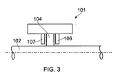
- an alternative seal arrangement 101 is shown which comprises an alternative baffle design.
- the seal arrangement 101 comprises a downstream baffle 106 and an upstream baffle 107 either side of the seal-pack 104.
- Each of the baffles 106, 107 is in the form of an adjustable iris diaphragm shown in isolation in Figures 4a and 4b , comprising a pair of concentric, relatively rotatable actuator rings 111, 112 and two circumferential rows of iris elements 113.
- Each of the iris elements 113 is pivoted to one of the actuator rings, in this case the inner actuator ring 111, at a pivot point 113a and further comprises a key 113b which is slidably guided in a corresponding radial key-way (not shown in Figures 4a and 4b ) in the other actuator ring, in this case the outer actuator ring 112.
- the inner edge of each iris element 113 defines a first circular-arced portion 113c having a radius, A, and a second circular-arced portion 113d having a smaller radius, B (see Figure 4b ).
- each of the baffles 106, 107 can be adjusted between a first position, shown in Figure 4a , in which the circular-arced portions 113c are in a first configuration and define a circular aperture of radius A, and a second position, shown in Figure 4b in which the circular-arced portions 113c are in a second configuration and form a circular aperture of smaller radius, B.
- Each baffle 106, 107 is therefore effectively retractable from a closed position (defining an aperture of radius B around the rotating element 102) to an open position (defining a central aperture of larger radius, A, around the rotating element 102) in order to adjust the baffle 106, 107.
- the respective control arrangement for controlling the baffles 106, 107 may comprise a motor (not shown) or some other actuator operably connected to one of the actuator rings 111, 112 for rotation of that actuator ring relative to the other actuator ring.
- a motor may be operably coupled to the outer actuator ring 112 and the inner actuator ring may then be fixed with respect to the outer ring, for example by fixing to the rotor casing (not shown).
- the relevant actuator may be linked to the relevant actuator ring 111, 112 by any suitable series of gears, levers or linkages.
- a common actuator may be used for both baffles 106, 107 or the baffles 106, 107 may be driven by separate actuators.
- the actuator may drive rotation of the relevant actuator ring 111, 112 in response to a differential pressure measured by a differential pressure sensor, which may comprise an upstream pressure sensor and a downstream pressure sensor.
- a differential pressure sensor which may comprise an upstream pressure sensor and a downstream pressure sensor.
- the actuator may drive the relevant actuator ring in response to a sensor-based measurement of the rotation speed of the rotating element 102.
- a suitable feedback control loop may be used to control each actuator.
- Figure 5 shows one possible control loop 117 for controlling respective separate actuators 114, 115 associated with the baffles 106, 107.
- the control loop 117 comprises inputting sensor signals (in this case upstream and downstream pressure signals) from sensors 118, 119 to a control unit 116, and using the control unit 116 to determine a suitable control signal for each actuator 114, 115 on the basis of the inputted sensor signals and a respective feedback signal indicating the current position of the baffle 106, 107.
- the control unit 116 may determine the control signals using a suitable pre-stored algorithm, based on a predetermined, desired seal characteristic.
- the baffles 106, 107 are arranged for movement independently of one another so that they may be independently adjusted.
- Figures 6a to 6d show various relative positions for the baffles 106, 107.
- the baffle 107 is in a fully retracted (open) position and the baffle 106 is in a fully extended (closed) position.
- the principal leakage flow through the seal pack 104 is downward towards the base of the baffle 106, as indicated by the arrows, thus creating maximum blow-down effect on the seal pack 104.
- the baffle 107 is in a fully extended (closed) position and the baffle 106 is in a fully retracted (open) position.
- the principal leakage flow through the seal-pack 104 is upwards away from the base of the baffle 107, as indicated by the arrows, thus reducing the blow-down effect on the seal-pack 104 and, specifically, creating maximum blow-up effect on the seal pack 104.
- both of the baffles 106, 107 are in the fully retracted (open) position.
- the principal leakage flow will be directed parallel to the rotating element 102, and the position of the baffles 106, 107 may thus be considered to be neutral, in the sense that they promote neither a blow-down nor a blow-up effect on the seal-pack 104. Nevertheless, the leakage cross-section will be maximised due to the relatively large exposed area of the seal pack 104.
- both of the baffles 106, 107 are in the fully extended (closed) position.
- the principal leakage flow will again be directed parallel to the rotating element 102, so that the baffles 106, 107 are in a neutral position, but the leakage cross-section will be minimised.
- the baffles 106, 107 may be adjusted to the position shown in Figure 6a at a relatively low engine power, and then adjusted to the position in Figure 6b, 6c or 6d at a relatively high engine power.
- independent radial adjustment of the baffles 106, 107 allows for a degree of independent control of the differential pressure across the seal-pack 104, which it is envisaged may allow control of bearing loads.
- any suitable iris diaphragm design may be used for each baffle other than the specific arrangement shown in Figures 4a and 4b , including arrangements allowing for continuous adjustment of the baffles between the open and closed position.
- any suitable control arrangement may be used for adjusting the position of the baffles.
- the embodiment shown in Figure 1 might equally utilise one or more actuators (such as motors), which may be driven either in response to a differential pressure measured by a pressure sensor or a sensor-based measurement of the rotation speed of the rotating element.
- the embodiment shown in Figure 3 might additionally or alternatively utilise a piston arrangement as part of the control arrangement for adjusting the baffles.
- a single seal arrangement according to the present invention also allows for flexible pre-adjustment of the position of the baffle plates, prior to operation of the rotating element for a given operating period, even where the position of the baffle plates is then subsequently fixed for the remainder of the operating period (for example to provide a pre-determined desired blow-down effect at a given optimal differential pressure or rotation speed).
- the baffles may be adjustable both in the radial direction and in the axial direction, either independently or concurrently.
- the control arrangement may utilise separate adjustment mechanisms for axial and radial adjustment; for example, the control arrangement may utilise a piston arrangement similar to that in Figure 1 for axial adjustment, and an actuator-driven iris diaphragm arrangement similar to that in Figure 3 for radial adjustment.
Landscapes
- Engineering & Computer Science (AREA)
- General Engineering & Computer Science (AREA)
- Mechanical Engineering (AREA)
- Sealing Devices (AREA)
- Turbine Rotor Nozzle Sealing (AREA)
Applications Claiming Priority (1)
| Application Number | Priority Date | Filing Date | Title |
|---|---|---|---|
| GB0811867A GB2461506B (en) | 2008-06-30 | 2008-06-30 | A seal arrangement |
Publications (3)
| Publication Number | Publication Date |
|---|---|
| EP2141392A2 true EP2141392A2 (de) | 2010-01-06 |
| EP2141392A3 EP2141392A3 (de) | 2010-01-27 |
| EP2141392B1 EP2141392B1 (de) | 2011-11-02 |
Family
ID=39683323
Family Applications (1)
| Application Number | Title | Priority Date | Filing Date |
|---|---|---|---|
| EP09250797A Ceased EP2141392B1 (de) | 2008-06-30 | 2009-03-20 | Dichtungsanordnung |
Country Status (3)
| Country | Link |
|---|---|
| US (1) | US8490980B2 (de) |
| EP (1) | EP2141392B1 (de) |
| GB (1) | GB2461506B (de) |
Families Citing this family (13)
| Publication number | Priority date | Publication date | Assignee | Title |
|---|---|---|---|---|
| US8205889B2 (en) * | 2007-11-27 | 2012-06-26 | General Electric Company | Methods and apparatus to facilitate sealing in rotary machines |
| US8317464B2 (en) * | 2010-02-16 | 2012-11-27 | General Electric Company | Reverse flow tolerant spring activated brush seal |
| US8794918B2 (en) | 2011-01-07 | 2014-08-05 | General Electric Company | System for adjusting brush seal segments in turbomachine |
| US9121297B2 (en) | 2011-03-28 | 2015-09-01 | General Electric Company | Rotating brush seal |
| US9255486B2 (en) | 2011-03-28 | 2016-02-09 | General Electric Company | Rotating brush seal |
| JP5804893B2 (ja) * | 2011-10-26 | 2015-11-04 | 三菱重工業株式会社 | 軸シール装置及びこれを備える回転機械 |
| US9790863B2 (en) | 2013-04-05 | 2017-10-17 | Honeywell International Inc. | Fluid transfer seal assemblies, fluid transfer systems, and methods for transferring process fluid between stationary and rotating components using the same |
| US9121299B2 (en) * | 2013-06-05 | 2015-09-01 | General Electric Company | Axially retractable brush seal system |
| US9829107B2 (en) * | 2016-04-12 | 2017-11-28 | Korea Institute Of Science And Technology | Oil sealing device for a bearing |
| US11118469B2 (en) | 2018-11-19 | 2021-09-14 | General Electric Company | Seal assembly for a turbo machine |
| US10968762B2 (en) | 2018-11-19 | 2021-04-06 | General Electric Company | Seal assembly for a turbo machine |
| US12540558B2 (en) * | 2022-08-23 | 2026-02-03 | General Electric Company | Active clearance control valves and related methods |
| CN119177884A (zh) | 2023-06-23 | 2024-12-24 | 通用电气公司 | 对壳体振动具有鲁棒性的面密封件 |
Citations (1)
| Publication number | Priority date | Publication date | Assignee | Title |
|---|---|---|---|---|
| EP2105640A1 (de) | 2008-03-28 | 2009-09-30 | ALSTOM Technology Ltd | Blattdichtung für Turbomaschine |
Family Cites Families (8)
| Publication number | Priority date | Publication date | Assignee | Title |
|---|---|---|---|---|
| US5318309A (en) * | 1992-05-11 | 1994-06-07 | General Electric Company | Brush seal |
| GB9929587D0 (en) * | 1999-12-16 | 2000-02-09 | Rolls Royce Plc | A seal arrangement |
| GB0028408D0 (en) * | 2000-11-22 | 2001-01-03 | Rolls Royce Plc | Seal apparatus |
| CA2359933C (en) * | 2001-02-08 | 2006-03-14 | Mitsubishi Heavy Industries, Ltd. | Shaft seal and gas turbine |
| US6786487B2 (en) * | 2001-12-05 | 2004-09-07 | General Electric Company | Actuated brush seal |
| GB0613543D0 (en) * | 2006-07-07 | 2006-08-16 | Rolls Royce Plc | Leaf seal arrangement |
| US20080136112A1 (en) * | 2006-12-08 | 2008-06-12 | United Technologies Corporation | Brush seal assemblies utilizing a threaded fastening method |
| US7744092B2 (en) * | 2007-04-30 | 2010-06-29 | General Electric Company | Methods and apparatus to facilitate sealing in rotary machines |
-
2008
- 2008-06-30 GB GB0811867A patent/GB2461506B/en not_active Expired - Fee Related
-
2009
- 2009-03-20 EP EP09250797A patent/EP2141392B1/de not_active Ceased
- 2009-03-25 US US12/382,851 patent/US8490980B2/en not_active Expired - Fee Related
Patent Citations (1)
| Publication number | Priority date | Publication date | Assignee | Title |
|---|---|---|---|---|
| EP2105640A1 (de) | 2008-03-28 | 2009-09-30 | ALSTOM Technology Ltd | Blattdichtung für Turbomaschine |
Also Published As
| Publication number | Publication date |
|---|---|
| EP2141392B1 (de) | 2011-11-02 |
| EP2141392A3 (de) | 2010-01-27 |
| GB2461506A (en) | 2010-01-06 |
| GB2461506B (en) | 2010-08-25 |
| GB0811867D0 (en) | 2008-07-30 |
| US20090322028A1 (en) | 2009-12-31 |
| US8490980B2 (en) | 2013-07-23 |
Similar Documents
| Publication | Publication Date | Title |
|---|---|---|
| EP2141392B1 (de) | Dichtungsanordnung | |
| EP3450781B1 (de) | Lageranordnung umfassend dämpfer mit verstellbarer dichtung | |
| US8939709B2 (en) | Clearance control for a turbine | |
| US8449243B2 (en) | Device and method for axially displacing a turbine rotor | |
| US8292571B2 (en) | Apparatus and method for clearance control of turbine blade tip | |
| JP5126505B2 (ja) | 可変ピッチブレードの制御 | |
| US20100260591A1 (en) | Spanwise split variable guide vane and related method | |
| EP2211026A2 (de) | Variable Statorschaufelanordnung in einer Gasturbine | |
| JPH03271503A (ja) | ブレード先端クリアランス制御装置 | |
| CA2660265C (en) | Leaf seal for turbomachine | |
| JP2010270757A (ja) | 能動的ロータアライメント制御システム及び方法 | |
| GB2559910A (en) | Variable stator blade control device | |
| CN102242644A (zh) | 用于轴流式涡轮机的环形的流动通道的具有径向缝隙调节功能的通道壁段 | |
| EP2604894A1 (de) | Verbesserte Lamellendichtung | |
| WO2009133334A2 (en) | A variable geometry turbine | |
| KR20170005453A (ko) | 가변 정익 장치의 메인터넌스 방법 및 가변 정익 장치 | |
| EP2949920B1 (de) | Vorrichtung zur Nutzung von Wellenenergie | |
| CA2676012A1 (en) | Turbo engine | |
| JP2007162482A (ja) | 軸流タービン | |
| CA2661004C (en) | Position feedback device for rotatable member | |
| KR20160087219A (ko) | 가변 베인 구동용 레버암 조립체 | |
| CN115045865A (zh) | 静子叶片的调节装置及包含其的压气机 | |
| ITTO20121149A1 (it) | Pompa a palette a cilindrata regolabile e metodo per la regolazione della cilindrata di tale pompa. | |
| US20090226306A1 (en) | Apparatus and method for adjusting a bearing array in a gas turbine aircraft engine | |
| US10837308B2 (en) | Device for controlling variable-pitch members in a turbomachine |
Legal Events
| Date | Code | Title | Description |
|---|---|---|---|
| PUAI | Public reference made under article 153(3) epc to a published international application that has entered the european phase |
Free format text: ORIGINAL CODE: 0009012 |
|
| PUAL | Search report despatched |
Free format text: ORIGINAL CODE: 0009013 |
|
| AK | Designated contracting states |
Kind code of ref document: A2 Designated state(s): AT BE BG CH CY CZ DE DK EE ES FI FR GB GR HR HU IE IS IT LI LT LU LV MC MK MT NL NO PL PT RO SE SI SK TR |
|
| AX | Request for extension of the european patent |
Extension state: AL BA RS |
|
| AK | Designated contracting states |
Kind code of ref document: A3 Designated state(s): AT BE BG CH CY CZ DE DK EE ES FI FR GB GR HR HU IE IS IT LI LT LU LV MC MK MT NL NO PL PT RO SE SI SK TR |
|
| AX | Request for extension of the european patent |
Extension state: AL BA RS |
|
| 17P | Request for examination filed |
Effective date: 20100125 |
|
| 17Q | First examination report despatched |
Effective date: 20100222 |
|
| AKX | Designation fees paid |
Designated state(s): DE FR GB |
|
| GRAP | Despatch of communication of intention to grant a patent |
Free format text: ORIGINAL CODE: EPIDOSNIGR1 |
|
| GRAS | Grant fee paid |
Free format text: ORIGINAL CODE: EPIDOSNIGR3 |
|
| GRAA | (expected) grant |
Free format text: ORIGINAL CODE: 0009210 |
|
| AK | Designated contracting states |
Kind code of ref document: B1 Designated state(s): DE FR GB |
|
| REG | Reference to a national code |
Ref country code: GB Ref legal event code: FG4D |
|
| REG | Reference to a national code |
Ref country code: DE Ref legal event code: R096 Ref document number: 602009003416 Country of ref document: DE Effective date: 20120119 |
|
| PLBE | No opposition filed within time limit |
Free format text: ORIGINAL CODE: 0009261 |
|
| STAA | Information on the status of an ep patent application or granted ep patent |
Free format text: STATUS: NO OPPOSITION FILED WITHIN TIME LIMIT |
|
| 26N | No opposition filed |
Effective date: 20120803 |
|
| REG | Reference to a national code |
Ref country code: DE Ref legal event code: R097 Ref document number: 602009003416 Country of ref document: DE Effective date: 20120803 |
|
| REG | Reference to a national code |
Ref country code: FR Ref legal event code: PLFP Year of fee payment: 8 |
|
| REG | Reference to a national code |
Ref country code: FR Ref legal event code: PLFP Year of fee payment: 9 |
|
| REG | Reference to a national code |
Ref country code: FR Ref legal event code: CA Effective date: 20170517 |
|
| REG | Reference to a national code |
Ref country code: FR Ref legal event code: PLFP Year of fee payment: 10 |
|
| PGFP | Annual fee paid to national office [announced via postgrant information from national office to epo] |
Ref country code: DE Payment date: 20190327 Year of fee payment: 11 Ref country code: FR Payment date: 20190325 Year of fee payment: 11 |
|
| PGFP | Annual fee paid to national office [announced via postgrant information from national office to epo] |
Ref country code: GB Payment date: 20190404 Year of fee payment: 11 |
|
| REG | Reference to a national code |
Ref country code: DE Ref legal event code: R119 Ref document number: 602009003416 Country of ref document: DE |
|
| PG25 | Lapsed in a contracting state [announced via postgrant information from national office to epo] |
Ref country code: FR Free format text: LAPSE BECAUSE OF NON-PAYMENT OF DUE FEES Effective date: 20200331 Ref country code: DE Free format text: LAPSE BECAUSE OF NON-PAYMENT OF DUE FEES Effective date: 20201001 |
|
| GBPC | Gb: european patent ceased through non-payment of renewal fee |
Effective date: 20200320 |
|
| PG25 | Lapsed in a contracting state [announced via postgrant information from national office to epo] |
Ref country code: GB Free format text: LAPSE BECAUSE OF NON-PAYMENT OF DUE FEES Effective date: 20200320 |