EP2141827A2 - Mobiles Endgerät eines Kommunikationssystems über Funkwellen vom Typ DECT und Steuerungsverfahren der Antennen dieses Endgeräts - Google Patents
Mobiles Endgerät eines Kommunikationssystems über Funkwellen vom Typ DECT und Steuerungsverfahren der Antennen dieses Endgeräts Download PDFInfo
- Publication number
- EP2141827A2 EP2141827A2 EP09162543A EP09162543A EP2141827A2 EP 2141827 A2 EP2141827 A2 EP 2141827A2 EP 09162543 A EP09162543 A EP 09162543A EP 09162543 A EP09162543 A EP 09162543A EP 2141827 A2 EP2141827 A2 EP 2141827A2
- Authority
- EP
- European Patent Office
- Prior art keywords
- terminal
- antenna
- signal
- antennas
- master
- Prior art date
- Legal status (The legal status is an assumption and is not a legal conclusion. Google has not performed a legal analysis and makes no representation as to the accuracy of the status listed.)
- Granted
Links
Images




Classifications
-
- H—ELECTRICITY
- H04—ELECTRIC COMMUNICATION TECHNIQUE
- H04B—TRANSMISSION
- H04B7/00—Radio transmission systems, i.e. using radiation field
- H04B7/02—Diversity systems; Multi-antenna system, i.e. transmission or reception using multiple antennas
- H04B7/04—Diversity systems; Multi-antenna system, i.e. transmission or reception using multiple antennas using two or more spaced independent antennas
- H04B7/08—Diversity systems; Multi-antenna system, i.e. transmission or reception using multiple antennas using two or more spaced independent antennas at the receiving station
- H04B7/0802—Diversity systems; Multi-antenna system, i.e. transmission or reception using multiple antennas using two or more spaced independent antennas at the receiving station using antenna selection
- H04B7/0805—Diversity systems; Multi-antenna system, i.e. transmission or reception using multiple antennas using two or more spaced independent antennas at the receiving station using antenna selection with single receiver and antenna switching
- H04B7/0808—Diversity systems; Multi-antenna system, i.e. transmission or reception using multiple antennas using two or more spaced independent antennas at the receiving station using antenna selection with single receiver and antenna switching comparing all antennas before reception
- H04B7/0811—Diversity systems; Multi-antenna system, i.e. transmission or reception using multiple antennas using two or more spaced independent antennas at the receiving station using antenna selection with single receiver and antenna switching comparing all antennas before reception during preamble or gap period
Definitions
- the present invention relates to a mobile terminal of a DECT type radio frequency communication system, installed on a support that can move, said terminal being equipped with a plurality of antennas and having means for measuring the power level. a signal received by each antenna and means for selecting one of these antennas as receiving antenna by comparing the power levels thus measured.
- the invention also relates to an antenna management method for exchanging a beacon or traffic signal of a radiofrequency communication established between communication terminals.
- a radiofrequency communication is used to deploy in a given environment a service of audio and / or data transfer type in which communication terminals communicate between them data that are either voice or other, such as for example images , data files, etc.
- a radiofrequency communication consists in transporting these data by radiofrequency waves propagating in this environment so that the signal carrying this data is conveyed from a transmitting terminal to either a receiver terminal or several receiving terminals in the case where the signal is broadcast.
- the present invention is described later in the case of a network defined by the DECT (Digital Enhanced Cordless Telecommunications) standards but the invention is intended to be implemented for other communication networks of this type, that is to say TDMA communication networks with time and frequency synchronization of communication terminals, hereinafter referred to as slave terminals, with a communication terminal, hereinafter referred to as the master terminal, and this from a beacon signal broadcast by this master terminal, each of the terminals being equipped with a plurality of antennas and comprising means making it possible to implement an antenna diversity mechanism, that is to say means for measuring the power level of a signal received by each antenna and means for selecting one of these antennas as a reception antenna by comparing the power levels thus measured.
- DECT Digital Enhanced Cordless Telecommunications
- a DECT type network is a TDMA network, that is to say a network in which the data exchanged between terminals are transmitted as digital data in time slots (English slots).
- time slots English slots
- slot we use the term slot to designate such a time interval because it is the term that is used by the skilled person. It will be written in italics to mark its Anglo-Saxon origin.
- Time division multiple access allows different users to share, over time, the use of a given frequency band, which is defined by a so-called TDMA frame which sets the time slots.
- the TDMA frame is defined, in the particular case of a system based on the DECT standards, as being a set consisting of 24 successive slots denoted s0 to s23 represented in FIG. Fig. 1 .
- the duration of the TDMA frame is then at least equal to the sum of the durations of these 24 slots.
- the duration of a frame is fixed at 10ms.
- the first twelve slots are dedicated to the transmission of the master terminal to the slave terminal and the last twelve slots are dedicated to the transmission of the slave terminal to the master terminal.
- the DECT frame is thus divided into two parts of 5ms each.
- the master terminal broadcasts a beacon signal that any other slave terminal must receive in order to be able, on the one hand, to synchronize in time and frequency with the master terminal and, on the other hand, , that the The master terminal allocates radio resources for each slave terminal and communicates to each slave terminal the radio resources allocated to it for communication to be established and maintained between itself and the slave terminal.
- the allocation of radio resources by a master terminal for establishing communication with a slave terminal is to dedicate a carrier consisting of two TDMA frame slots, one on the referenced sn Fig. 1 for data transmission and the other referenced s (n + 12) for data reception.
- DECT has defined an antenna diversity scheme and a timing of said advance mechanism which are implemented by a protocol defined by ETSI EN 300 175-3 V1.4.2 (1999-06) Part 3: Medium Access Control (MAC) layer.
- MAC Medium Access Control
- the antenna diversity mechanism is usually implemented to improve the quality of the received signals, and in particular to overcome the multiple paths due to the reflection of waves on obstacles, such as buildings, located between the terminals. then in communication.
- the timing advance mechanism is conventionally used in digital communication mechanism. It consists in sending to each slave terminal a time value, defined according to the distance between this slave terminal and the master terminal, so that the slave terminal advances or delays the transmission of its frames.
- the Fig. 2 schematically represents the protocol exchanges between a slave terminal TE and a master terminal TM which are required by the DECT standard prior to the implementation of the antenna diversity and timing advance mechanism.
- the antenna diversity and timing advance mechanisms require that a communication be established between the slave terminal TE and the master terminal TM, that is to say that the slave terminal TE has received the carrier. which is allocated to it by the master terminal TM for this communication.
- the master terminal TM sends to all the slave terminals via a beacon signal that it is able to exchange long preamble frames (step 1) during a communication.
- a slave terminal TE which wants to establish a communication with the master terminal TM, replies that it is also able to exchange long preamble frames via a "quality" message (step 2). Therefore, the two terminals exchange long preamble frames and receive these frames by implementing the diversity mechanism. of antennas (step 3).
- the master terminal TM when in communication, can establish the forward / backward propagation time of the wave and thus determine the distance separating it from the slave terminal TE.
- the master terminal TM determines a first timing advance value as a function of this distance and sends it to the slave terminal TE so that the slave terminal TE delays or advances its frame transmission start time (step 4). .
- the diversity mechanism is not implemented and the type of frames exchanged during the communication is a normal preamble frame, it is that is to say a frame comprising a field S followed by a field D relating to the useful data to be transmitted. It may be noted that the timing advance mechanism is however implemented.
- the Fig. 3 schematically represents the temporal evolution of a DECT frame with normal preamble. At the top of the Fig. 3 is represented the digital version of the modulated DECT frame while at the bottom of the Fig. 3 , is represented the analog version of the DECT frame to be modulated.
- Field S has a 16 bit preamble P and a sync word SW also 16 bits.
- the preamble P is subdivided into 4 words of 4 bits each whose hexadecimal values are respectively 0xA, 0xA, 0xA, 0xA (or 0x5, 0x5, 0x5, 0x5 as will be seen later), and the synchronization word SW is subdivided into 4 words of 4 bits each whose hexadecimal values are respectively 0xE, 0x9, 0x8, 0xA (or 0x1, 0x6, 0x7, 0x5, as will also be seen later).
- the transmission nominal power of the frame gradually increases from a zero value to a maximum value P max during a so-called attack period.
- the Fig. 4 schematically represents the temporal evolution of a long preamble DECT frame.
- a word B of 16 bits alternatively equal to 0 and 1.
- a transmitting terminal for example the master terminal TM
- transmits a long preamble frame TR1 to another terminal for example the slave terminal TE
- the master terminal TM waits for reception of a long preamble frame TR2 transmitted by the slave terminal TE.
- the word B of the frame TR2 is complementary to the word B of the frame TR1, that is to say that when a bit of the word B of the frame TR1 is 0, that of the frame TR2 is equal to 1 and conversely, the 4 words from preamble P of the frame TR1 have for hexadecimal values 0xA, 0xA, 0xA, 0xA while those of the frame TR2 have values 0x5, 0x5, 0x5, 0x5 and the 4 words of the synchronization word SW of the frame TR1 have hexadecimal values 0xE, 0x9, 0x8, 0xA while those of the TR2 frame have hexadecimal values 0x1, 0x6, 0x7, 0x5.
- the hexadecimal values of the words of the preamble P and of the synchronization field SW of the frame TR2 are thus also complementary to the hexadecimal values of the words of the preamble P and of the synchronization field SW of the frame TR1.
- the master terminal TM selects one of the two antennas ⁇ E1 or AE2 as receiving antenna, in this case the one on which the measured power level is the highest.
- the rest of the frame TR2 is then received, preamble P, synchronization fields SW and data D, from this reception antenna thus selected in this case the antenna AE1 according to the example of the Fig. 4 .
- radiofrequency waves carrying data to be transmitted must not be excessively attenuated between the master terminal and the slave terminal with which it is in communication.
- the power level of the radiofrequency waves carrying the beacon signal is sufficient so that the slave terminal can synchronize with the master terminal and establish a new communication.
- the attenuation of the power level of a radiofrequency wave is due, in particular, to the masking of the antenna by the support that carries the terminal such as a person or a vehicle. Indeed, a part of this support such as for example the head of a person or another part of his body, can cause in certain situations the attenuation of this wave and thus form what is commonly called shadow areas, that is, areas where this part of the medium obscures the receiving antenna.
- each terminal whether master or slave, is carried by a person who can move at any time and where each terminal has a plurality of antennas mounted solidarity on the terminal, itself fixed on the chest of the person.
- Each terminal is provided with an antenna diversity mechanism that allows it to select the receiving antenna on which the highest power level is measured.
- the master terminal TM broadcasts a beacon signal in the Z zone whose power level is sufficient for each slave terminal TEi can receive this signal.
- the beacon signal power level is not homogeneous over the entire zone Z. Indeed, the body of the person M creates a shadow zone Z1 for this antenna which is located roughly on the back of the person M. It may be noted that since the antennas of the terminal TM are all integral with the terminal TM fixed on the chest of the person M, a shadow area is created by the body of the person whatever the antenna used for the broadcast of the signal. tag.
- the power level of the beacon signal in the zone Z1 is always attenuated with respect to the power level of this signal in the rest of the zone Z.
- This attenuation is all the more important for the person E2, because of its relative position relative to the person M.
- each antenna terminal TE2 is in a shadow zone Z2 caused by the body of the person E2, thus inducing further attenuation of the signal of tag.
- the person E3 is positioned so that the antennas of his terminal TE3 receive the beacon signal without attenuation. It will be recalled here that the influence of the distance separating the terminals on the attenuation of the transmitted signal is not considered because all the slave terminals are at the same distance from the person M.
- the person E4 is positioned so that his body creates a shadow zone Z3 for the antennas of its terminal causing the attenuation of the beacon signal received.
- Radiofrequency communication systems in which the communication terminals are carried by supports that are able to move relative to each other and which each comprise a plurality of antennas are systems that do not allow to ensure a quality stable transmission because these antennas can be hidden by the support that wears them creating areas of shadows on these antennas.
- the radio link budget can be very different. Indeed, the inventor has observed that certain configurations of the supports relative to each other cause the breaking of the reception of the beacon signal by a slave terminal TEi, thus preventing this slave terminal from establishing a communication with the master terminal. TM. Likewise, certain configurations of the supports with respect to each other caused the reception of traffic signals by a slave terminal TEi to break off, thereby breaking the communication that was established between this slave terminal TEi and the master terminal M.
- One of the aims of the present invention is to overcome this problem of shadows by positioning in particular the antennas of each terminal.
- the invention relates to a mobile terminal of a DECT type radio frequency communication system, installed on a support that can move, said terminal being equipped with a plurality of antennas and comprising means for measuring the power level of a signal received by each antenna and means for selecting one of these antennas as an antenna of reception by comparison of the power levels thus measured.
- the terminal is characterized in that the antennas are positioned on portions of said support so that each shadow zone of each antenna, which is caused by a portion of the support, is covered by another antenna of said terminal.
- the means for measuring the power level of a signal received by each antenna and the means for selecting one of these antennas as a reception antenna are activated as soon as the slave terminal is synchronized.
- an antenna selection mechanism comparable to the antenna diversity mechanism defined by the DECT standard, is implemented when a beacon signal is received and this, upon synchronization of a slave terminal while the Antenna diversity mechanism according to the DECT standard is inoperative until communication is established between the terminals.
- the means for measuring the power level of a signal received by each antenna and the means for selecting one of these antennas as a reception antenna are used at each reception of a signal by the terminal thus conferring a dynamic character. to this antenna selection mechanism.
- This is advantageous because the reception of a signal by the antenna selected as the receiving antenna is optimal regardless of the relative positions of the supports and this with each unpredictable movement of one or the other or both supports.
- the selected reception antenna is used for transmitting a signal.
- This embodiment is advantageous because the selection of the receiving antenna is made dynamically to receive each signal optimally, the transmission by this terminal of a signal following the reception of another signal, classic scenario in communication , makes it possible to optimize that the emission of this signal is also made under optimal conditions because the support bearing the receiving terminal has very little chance of moving between the reception and the emission of a signal.
- the terminal being intended to be worn by a person and said terminal being equipped with two antennas, one of the antennas is deported on a shoulder of said person and the other antenna is positioned on the chest of said nobody.
- the offset antenna on the shoulder covers the shadow area of the antenna located on the chest of the person, essentially located behind the person and vice versa the antenna located on the chest of the person allows to cover the shadow area of the antenna located on the shoulder of the person, zone located essentially in front of the person.
- the offset antenna on the shoulder is inclined relative to the vertical at an angle at most equal to 45 degrees and the antenna positioned on the chest of the person is secured to the terminal and is kept upright.
- such a positioning of the two antennas allows that whatever the observed side of the person standing, at least one of the two antennas is always visible from an antenna carried by another person.
- the remote antenna is a dipole antenna.
- This type of antenna makes it possible to obtain a deformation of the radiation pattern of the reduced antenna compared with, for example, a patch-type antenna, which is more sensitive to the proximity of the support.
- the terminal being provided for broadcasting a beacon signal
- said beacon signal is systematically transmitted on the antenna of said terminal which is the clearest of the support.
- the inventor has observed that the antenna diversity mechanism proposed by the DECT standard, in addition to requiring the terminals to be in communication, operates only when the relative distance between terminals remains low.
- the Fig. 6 is a timing diagram which illustrates the transmission of a TR1 frame between a master terminal TM and a slave terminal TE remote from each other.
- the distances D1 and D2 are equal to a distance D.
- Cumulative ⁇ wave propagation delays T 1 + ⁇ T 2 is not problematic when the terminals are distant from each other by a few meters. On the other hand, when this relative distance increases, the accumulation of propagation delays of the waves also increases, thus causing the arrival of the TR2 frame on the TM terminal more and more late. The RSSI measurement, made from the TR2 frame, is then distorted, as will be seen later, which has the effect of distorting the selection of receiving antenna. The accumulation of propagation delays, when it becomes important, is therefore disadvantageous because any request for carrier allocation, as well as any Connection Less Message Service (CLMS) message, will be done on an antenna which will not then be selected from correct RSSI measurements but selected by default on the only antenna that still receives signal at this time. The antenna diversity mechanism is then inoperative.
- CLMS Connection Less Message Service
- the Fig. 7 illustrates this problem of limiting the use of the antenna diversity mechanism defined by the DECT standard when the distances between terminals become important.
- the terminal TM transmits a long preamble frame TR1 of the beacon signal at time t0.
- the master terminal TM activates the antenna diversity mechanism by activating the start of the measurement RSSI on the antenna AE1 for a second time. duration of a DECT byte.
- the measurement of the power level on the antenna AE1 is then taken essentially on the byte B1 and the measurement of the power level on the antenna AE2 is taken on the B2 byte.
- RSSI measures are correct.
- the slave terminal TE moves away from the master terminal TM and transmits the frame TR2.
- the values of ⁇ ⁇ T 1 and T 2 increase and the accumulated delays of wave propagation is significant.
- TR2 frame transmitted by the slave terminal TE will be received at time t0 + ⁇ T 1 + ⁇ T 2 + 5ms rather than at the instant t0 + 5ms as expects the master terminal TM.
- the measurement of the power level on the antenna AE1 is then distorted because only a part of the bits of the byte B1 is now taken into account in the measurement.
- the slave terminal TE again moves away from the terminal TM and transmits the frame TR2.
- the values of ⁇ t 1 and ⁇ T 2 increases accordingly until no byte bit B1 is not involved in the measurement of the power level on AE1 antenna while measuring the power level on antenna AE2 can always be done on the bits of the word B1.
- the antenna diversity mechanism is provided by the DECT standard to be operational at short range.
- the antenna diversity mechanism remains operational when the relative distance between terminals increases sharply.
- the inventor has observed that the size of the long preamble of the frame must be extended by at least a duration equal to twice the propagation time of a wave between the master terminal and a slave terminal when these terminals are located at the desired maximum distance.
- the inventor has observed that by maintaining the frame transmission power to a predefined value following the attack duration for a duration at least equal to the accumulation of the maximum propagation delays (round trip) desired of waves, the relative distance between terminals can be important while keeping operational the antenna diversity mechanism of the DECT standard.
- the terminal comprises means (MM) for maintaining the level of the long frame-to-frame transmission power of a signal to be transmitted at a constant value for a period of time (M), called hold time, and means (EM) for transmitting said signal during said hold period.
- M period of time
- EM means for transmitting said signal during said hold period.
- the hold time is twice the propagation time of a wave between said terminal and another terminal located at a predetermined maximum distance, plus the propagation time in the radio frequency circuits.
- the constant value is defined such that the measurement of the signal received on an antenna during a portion of the hold duration equal to the duration of one byte of the long preamble is equivalent to the measurement of the power level of a received signal which would be made from a byte of the long preamble.
- the constant value is equal to the maximum transmit power value of the frame.
- the measured power level of a signal received during this hold time is equivalent to the power level measured on a byte of a long preamble word, thus making it possible to increase the distance between terminals by increasing the holding time.
- a signal transmitted by a communication network is frequency modulated on the transmitter side and demodulated on the receiver side.
- the demodulation of a received frame starts at a fixed instant at the first bit of the long preamble, that is to say from the first bit of the B1 byte when the distance between terminals is zero.
- the terminal comprises means for forcing the demodulation of a received signal to start from the moment fixed at the first bit of the normal preamble of the long preamble frame when the distance between the two terminals is zero.
- This feature makes reliable the measurement of the power level on each antenna.
- the present invention relates to an antenna management method for exchanging a beacon or traffic signal of a radio frequency communication established between a slave terminal and a master terminal of a radio network.
- DECT type communication Each terminal is equipped with a plurality of antennas and comprises means for measuring the power level of a signal received by each antenna and means for selecting one of these antennas as a reception antenna by comparing the power levels. thus measured.
- the method comprises a step of broadcasting a beacon signal by the master terminal.
- the beacon signal is emitted by the antenna which is the clearest of the support that carries it.
- the method also comprises a synchronization search step with the master terminal, in which each antenna of a slave terminal is considered in turn for a predetermined duration, and during each duration, it is checked whether a synchronization signal with the master terminal is received by the antenna considered during this time. In the case where an antenna receives the synchronization signal with the master terminal, the antenna is determined as being the receiving antenna of the slave terminal.
- said step of seeking synchronization with the master terminal is followed by a synchronization step of the slave terminal with the master terminal in which the slave terminal, once synchronized with the master terminal, activates its antenna selection mechanism.
- the synchronization step of the slave terminal with the master terminal is followed by a step of transmission by said slave terminal of a radio resource allocation request signal during which the slave terminal transmits, via the antenna used for receiving the synchronization signal with the master terminal, a radio resource allocation request signal DE, i.e. a request from a carrier, to the master terminal TM.
- the step of transmitting a radio resource allocation request signal is followed by a step of reception by the master terminal of the radio resource allocation request signal during which the master terminal tests if more An antenna receives the radio resource allocation request signal and then selects the receiving antenna as the one on which the measured power level of the received signal is highest.
- the step of reception by the master terminal of the radio resource allocation request signal is followed by a step of transmission by the master terminal of the radio resources allocated via the reception antenna selected when the reception signal is received. request for allocation of radio resources.
- the communication between the master terminal and the slave terminal is then established via the most relevant antennas, that is to say those which make it possible to optimize the quality of the communication.
- the step of transmission by the master terminal of the allocated radio resources is followed by a step of exchanges of traffic signals between the master terminal and the slave terminal, during which at each reception of a signal by, either the slave terminal, ie the master terminal, the receiving terminal tests whether more than one antenna receives a traffic signal and then selects the receiving antenna as the one on which the measured power level of the received signal is the highest.
- the reception antenna selected by a terminal is that used by this terminal to transmit a signal.
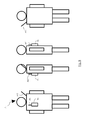
- the Fig. 8 represents an example of positioning of antennas on a PE person according to the invention.
- the four views of the PE person are represented at the Fig. 8 .
- the leftmost one is the front view. It shows the terminal TE, a first antenna AE1 and a second antenna AE2 which are positioned on parts of the person PE so that each shadow zone of each antenna which is caused by a part of the body of the person, head, chest, is covered by another antenna terminal TE.
- the AE2 antenna is offset on a shoulder of the PE person, in this case the left, and the antenna AE1 is positioned on the chest of the PE person.
- the AE2 antenna which is offset on the shoulder is inclined relative to the vertical at an angle at most equal to 45 degrees while the AE1 antenna is maintained in a vertical position and is integral with the terminal TE.
- the AE2 antenna is a dipole antenna.
- the reception antenna selected following the reception by a terminal of a traffic signal is used for the transmission of a traffic signal by this terminal.
- the terminal TE is equipped with means MES for measuring the power level of a signal received by each antenna AE1 and AE2 and means SEL for selecting one of these two antennas AE1 and AE2 as reception antenna by comparing the levels of power measured.
- the means MES and SEL which form an antenna selection mechanism, are activated at each reception of a signal by the terminal TE and this as soon as the terminal TE is synchronized with a master terminal.
- the Fig. 9 schematically represents the temporal evolution of a long preamble DECT frame according to the invention. At the top of the Fig. 9 is represented the digital version of the demodulated DECT frame while at the bottom of the Fig. 9 is represented the analog version of the demodulated DECT frame.
- Each terminal, slave TE or master TM comprises means MM for maintaining at a constant value the level of power transmission frame long preamble during a period M, said maintenance.
- This constant value is defined so that the RSSI measurement, made on an antenna during part of the hold time M equal to the duration of one byte of the long preamble, is equivalent to the measurement of the power level of a received signal that would be performed on this antenna from a byte of the long preamble.
- the constant value is equal to the maximum transmission power value of the frame P max .
- the holding time M is equal to twice the duration of propagation of a wave between the slave terminal TE and a master terminal TM located one from the other at a predetermined maximum distance D max , plus the propagation time.
- tF in radio frequency circuits.
- each terminal TE or TM comprises means EM for transmitting during the holding period M, a signal whose power level is equal to said constant value.
- Fig. 9 To the Fig. 9 is represented a frame TR2 transmitted by a slave terminal TE in response to a TR1 frame that it has previously received from the master terminal TM.
- the time evolution of the frame TR1 is similar to that represented by the Fig. 9 . Only the values of the words change, as explained in the introductory part.
- the Fig. 10 illustrates the demodulation by the terminal TM of a frame previously transmitted by the terminal TE according to the invention. It can be seen that the antenna diversity mechanism remains operational when the distance between terminals becomes important.
- Fig. 10 At the top of the Fig. 10 is represented the case where the slave terminal TE is close to the master terminal TM and TR2 transmits a frame at time t1 equal to t0 + 5ms here that the propagation delay ⁇ T 1 does not have a significant value.
- the measurement of the power level on the antenna AE1 1 is then based on the byte B1 and the measurement of the power level on the antenna AE2 is based on the B2 byte.
- RSSI measures are correct.
- the slave terminal TE again moves away from the terminal TM and transmits the frame TR2.
- the values of ⁇ t 1 and ⁇ T 2 increases accordingly until no byte bit B1 is not involved in the measurement of the power level on the antenna AE1.
- the power level on the antenna AE1 is then measured during a large part of the holding time M and gives a non-zero measurement despite the fact that the distance between the terminals is greater than the maximum operating distance of the antenna diversity mechanism which is defined by the DECT standard.
- the antenna diversity mechanism therefore remains operational at distances greater than this maximum distance defined by the DECT standard.
- a signal transmitted by a communication network is frequency modulated on the transmitter side and demodulated on the receiver side.
- the demodulation of a long preamble frame starts from the moment fixed at the first bit of the long preamble, that is to say from the -16 bit of the frame, instant fixed when the distance between terminals is zero.
- each terminal comprises DS means for constraining the demodulation of a received signal long preamble frame to start from an instant fixed to the first bit of the normal preamble of the frame when the distance between the two terminals is zero.
- a frame TR2 demodulated by the master terminal TM is represented as well as the activation of the antenna AE1 and AE2.
- the curve C1 represents the time evolution of the power levels relative to the TR1 frame that are received on the antennas, that is to say the time evolution of the RSSI measurements. It is noted that the power is established normally according to an arc of an exponential and then is disturbed starting from the moment fixed by the first bit of the long preamble noted bit -16 that is to say as soon as the demodulation of the TR2 frame is enabled.
- the curve C2 represents the temporal evolution of the power levels relative to the TR2 frame that are received on the antennas, that is to say the time evolution of the RSSI measurements when the DS means are implemented. It is found that the power is normally established according to an arc of an exponential and correctly reflects the power of the signal received on each antenna by differentiating the two power levels received. According to the example given, the antenna AE1 is selected to receive the frame TR1.
- the Fig. 12 represents a diagram of the steps of the antenna management method for exchanging a beacon or traffic signal of a radiofrequency communication established between a slave terminal TE and a master terminal TM of a communication network.
- the method is intended to be implemented by a master terminal and a slave terminal both provided, on the one hand, to transmit long preamble frames such as those defined by the DECT standard and, on the other hand, provided means, for example software, for implementing the antenna management method by associating it with the means MES, SEL, DS, MM and EM, as described above. Subsequently, the method is described by considering that each terminal is worn by a person and that this terminal is associated with an AE1 antenna, integral with this terminal, and an antenna AE2 remote on the shoulder of the person as illustrated over there Fig 5 . However, the method can be implemented when the terminal is carried on another support and more than two antennas are associated with it.
- the method comprises a step 100 of broadcasting a synchronization signal, in this case a beacon signal Sb, by a master terminal TM.
- a synchronization signal in this case a beacon signal Sb
- the beacon signal Sb is transmitted by the antenna AE2 of the master terminal TM, that is to say by the antenna which is the clearest of the medium, in this case the person.
- step 100 continues as long as the master terminal TM is in operation so that the broadcasting of the beacon signal is permanent.
- Step 100 is followed by a synchronization search step 200 with the master terminal, during which the antenna AE1 is considered for a predetermined duration DT1.
- the duration DT1 it is checked whether the beacon signal Sb is received on the antenna AE1. If so, the antenna AE1 is determined to be the receiving antenna. Otherwise, at the end of the duration DT1, the antenna AE2 is considered for a predetermined duration DT2, for example equal to the duration DT1. If so, the antenna AE1 is determined to be the receiving antenna. Otherwise, at the end of the duration DT2, the antenna AE1 is considered during the duration DT1, and so on until an antenna is determined as being a receiving antenna.
- step 300 of synchronization of the slave terminal TE with the master terminal TM during which the slave terminal , once synchronized with the master terminal, activates its antenna selection mechanism, that is to say the MES and SEL means.
- Step 300 is followed by a step 400 of transmission by the slave terminal TE of a radio resource allocation request signal during which the slave terminal TE transmits, via the reception antenna determined by its antenna selection mechanism, a radio resource allocation request signal DE, that is to say a request from a carrier, to the master terminal TM .
- Step 400 is followed by a step 500 of reception by the master terminal TM of the radio resource allocation request signal DE.
- the master terminal TM carries out an antenna diversity operation, that is to say that in the case where the signal DE is received by the two antennas AE1 and AE2, the antenna of selected reception is the one on which the signal power level DE is the highest.
- Step 500 is followed by a step 600 of transmission by the master terminal TM allocated radio resources, that is to say a carrier consisting of a slot sn dedicated to the transmission and a slot s (n + 12) dedicated to reception via the reception antenna selected when receiving the signal DE.
- the master terminal TM allocated radio resources that is to say a carrier consisting of a slot sn dedicated to the transmission and a slot s (n + 12) dedicated to reception via the reception antenna selected when receiving the signal DE.
- the communication between the master terminal TM and the slave terminal TE is then established on the most relevant antennas, thus eliminating the obstacle represented by the support.
- Step 600 is followed by a step 700 of traffic signal exchanges between the master terminal TM and the slave terminal TE.
- the slave terminal TE At each reception of a traffic signal, by the slave terminal TE, the slave terminal TE performs a selection operation of the best antenna.
- the master terminal TM At each reception of a traffic signal by the master terminal TM, the master terminal TM performs a selection operation of the best antenna.
- the beacon signal is always transmitted by the most unobstructed antenna of the support.
- the receiving antenna selected by the slave terminal TE is that used by the slave terminal TE to transmit a signal.
- the receiving antenna selected by the master terminal TM when receiving a traffic signal transmitted by the slave terminal TE is that used by the master terminal TM to transmit a traffic signal to said terminal slave TE .
Landscapes
- Engineering & Computer Science (AREA)
- Computer Networks & Wireless Communication (AREA)
- Signal Processing (AREA)
- Mobile Radio Communication Systems (AREA)
- Radio Transmission System (AREA)
Priority Applications (1)
| Application Number | Priority Date | Filing Date | Title |
|---|---|---|---|
| EP09175103.2A EP2190131B1 (de) | 2008-06-13 | 2009-06-12 | Verfahren zur antennensteuerung für ein dect-funkübertragungssystem und das entsprechende system |
Applications Claiming Priority (1)
| Application Number | Priority Date | Filing Date | Title |
|---|---|---|---|
| FR0853915A FR2932627B1 (fr) | 2008-06-13 | 2008-06-13 | Terminal mobile d'un systeme de communication par onde radiofrequence de type dect et procede de gestion des antennes de ce terminal |
Related Child Applications (2)
| Application Number | Title | Priority Date | Filing Date |
|---|---|---|---|
| EP09175103.2A Division EP2190131B1 (de) | 2008-06-13 | 2009-06-12 | Verfahren zur antennensteuerung für ein dect-funkübertragungssystem und das entsprechende system |
| EP09175103.2A Division-Into EP2190131B1 (de) | 2008-06-13 | 2009-06-12 | Verfahren zur antennensteuerung für ein dect-funkübertragungssystem und das entsprechende system |
Publications (3)
| Publication Number | Publication Date |
|---|---|
| EP2141827A2 true EP2141827A2 (de) | 2010-01-06 |
| EP2141827A3 EP2141827A3 (de) | 2010-01-20 |
| EP2141827B1 EP2141827B1 (de) | 2015-08-12 |
Family
ID=40257054
Family Applications (2)
| Application Number | Title | Priority Date | Filing Date |
|---|---|---|---|
| EP09175103.2A Active EP2190131B1 (de) | 2008-06-13 | 2009-06-12 | Verfahren zur antennensteuerung für ein dect-funkübertragungssystem und das entsprechende system |
| EP09162543.4A Active EP2141827B1 (de) | 2008-06-13 | 2009-06-12 | Mobiles Endgerät eines Kommunikationssystems über Funkwellen vom Typ DECT und Steuerungsverfahren der Antennen dieses Endgeräts |
Family Applications Before (1)
| Application Number | Title | Priority Date | Filing Date |
|---|---|---|---|
| EP09175103.2A Active EP2190131B1 (de) | 2008-06-13 | 2009-06-12 | Verfahren zur antennensteuerung für ein dect-funkübertragungssystem und das entsprechende system |
Country Status (2)
| Country | Link |
|---|---|
| EP (2) | EP2190131B1 (de) |
| FR (1) | FR2932627B1 (de) |
Cited By (1)
| Publication number | Priority date | Publication date | Assignee | Title |
|---|---|---|---|---|
| WO2012126755A1 (fr) * | 2011-03-22 | 2012-09-27 | Sagem Defense Securite | Dispositif de communication tdma à deux antennes émettant deux balises |
Families Citing this family (1)
| Publication number | Priority date | Publication date | Assignee | Title |
|---|---|---|---|---|
| FI129163B (en) * | 2020-06-10 | 2021-08-13 | Wirepas Oy | Resource scheduling system for a wireless communication network |
Citations (1)
| Publication number | Priority date | Publication date | Assignee | Title |
|---|---|---|---|---|
| WO1996002984A1 (en) | 1994-07-15 | 1996-02-01 | Telefonaktiebolaget Lm Ericsson | A method in a diversity receiver |
Family Cites Families (2)
| Publication number | Priority date | Publication date | Assignee | Title |
|---|---|---|---|---|
| US5960046A (en) * | 1996-12-03 | 1999-09-28 | Northern Telecom Limited | Preamble based selection diversity in a time division multiple access radio system |
| WO2001041330A1 (de) * | 1999-11-30 | 2001-06-07 | Fraunhofer-Gesellschaft zur Förderung der angewandten Forschung e.V. | Dect-sende/empfangs-endgerät und verfahren zum kommunizieren zwischen einem dect-sende/empfangs-endgerät und einer dect-basisstation |
-
2008
- 2008-06-13 FR FR0853915A patent/FR2932627B1/fr not_active Expired - Fee Related
-
2009
- 2009-06-12 EP EP09175103.2A patent/EP2190131B1/de active Active
- 2009-06-12 EP EP09162543.4A patent/EP2141827B1/de active Active
Patent Citations (1)
| Publication number | Priority date | Publication date | Assignee | Title |
|---|---|---|---|---|
| WO1996002984A1 (en) | 1994-07-15 | 1996-02-01 | Telefonaktiebolaget Lm Ericsson | A method in a diversity receiver |
Cited By (3)
| Publication number | Priority date | Publication date | Assignee | Title |
|---|---|---|---|---|
| WO2012126755A1 (fr) * | 2011-03-22 | 2012-09-27 | Sagem Defense Securite | Dispositif de communication tdma à deux antennes émettant deux balises |
| FR2973189A1 (fr) * | 2011-03-22 | 2012-09-28 | Sagem Defense Securite | Dispositif de communication tdma a deux antennes emettant deux balises |
| RU2600454C2 (ru) * | 2011-03-22 | 2016-10-20 | Сажем Дефенс Секюрите | Устройство связи с двумя антеннами, передающими два сигнала маяка, для системы множественного доступа с временным разделением |
Also Published As
| Publication number | Publication date |
|---|---|
| EP2141827A3 (de) | 2010-01-20 |
| FR2932627A1 (fr) | 2009-12-18 |
| FR2932627B1 (fr) | 2011-03-18 |
| EP2190131A3 (de) | 2012-08-22 |
| EP2190131B1 (de) | 2018-03-28 |
| EP2141827B1 (de) | 2015-08-12 |
| EP2190131A2 (de) | 2010-05-26 |
Similar Documents
| Publication | Publication Date | Title |
|---|---|---|
| EP0589753B1 (de) | Verfahren um zusammen mit einen Befehl zum Wechsel der Basisstation in einem zellularen System ein Laufzeitkorrektursignal an eine Mobilstation auszusenden | |
| EP3603235B1 (de) | Uwb-lokalisierungsverfahren mit hilfskanalsynchronisation | |
| EP0955784B1 (de) | Verfahren zum Weiterreichen zwischen zwei Relays einer Zelle eines digitalen zellularen Funkkommunikationssystems mittels eines gemeinsamen Übergangskanals. | |
| EP0593320A1 (de) | Verfahren zur Übertragung einer Zeitverschiebungsnachricht an ein Fahrzeug das sich in einem zellularen Funkfernsprechnetz bewegt sowie Fahrzeug, Steuerungsvorrichtung, und Nachrichtaustauschanordnung die dieses Verfahren verwenden | |
| EP2260655B1 (de) | Doppelte funkrelaisstation | |
| FR2941126A1 (fr) | Procedes de configuration d'antennes d'emission et de reception, produit programme d'ordinateur, moyen de stockage et noeuds correspondants | |
| EP0698318A1 (de) | Verfahren zum interzellularen umlegen oder weiterreichen zwischen zwei zellen eines zellenmobilfunknetzwerkes | |
| FR2766996A1 (fr) | Procede et dispositif permettant de reduire le blocage de signaux dans un systeme de telecommunications par satellites | |
| FR2751495A1 (fr) | Systeme de telecommunications a synchronisation temporelle | |
| EP0893931A1 (de) | Verfahren zur Bestimmung der Laufzeitkorrektur in einem zellularen funkkommunikationssystem | |
| FR2808160A1 (fr) | Procede de determination de la position d'une station mobile d'un reseau de telecommunication mobile | |
| EP1756987B1 (de) | Verfahren und system zur verteilten synchronisation | |
| EP0901184A1 (de) | Verfahren zur Kalibrierung von Sendeketten und/oder Empfangsketten für den Betrieb einer aktiven Gruppenantenne und Mobilstation dafür | |
| EP2394474B1 (de) | Übertragungsverfahren für ein drahtloses netzwerk und entsprechendes empfangsverfahren | |
| EP2141827B1 (de) | Mobiles Endgerät eines Kommunikationssystems über Funkwellen vom Typ DECT und Steuerungsverfahren der Antennen dieses Endgeräts | |
| FR2924818A1 (fr) | Systeme de radiolocalisation/positionnement au moyen d'un reseau ad hoc | |
| WO2001005063A1 (fr) | Procede et systeme de telecommunication par satellites defilants dans lequel les communications sont transferables d'un satellite a un autre | |
| FR2728422A1 (fr) | Systeme de radio-communication permettant de gerer des retards de transmission variables | |
| CA2296204C (fr) | Satellite a couverture omnidirectionnelle | |
| EP1181786A1 (de) | Verfahren zur funkübertragung zwischen einer basisstation und mobilfunkendgeräten | |
| FR2951340A1 (fr) | Procede de gestion d'acces a un reseau de communication resistant aux masquages, produit programme d'ordinateur et dispositifs correspondants. | |
| FR2724076A1 (fr) | Procede de conservation de la synchronisation temporelle d'une station mobile dans un systeme de radiocommunication numerique cellulaire | |
| FR2941125A1 (fr) | Procedes de configuration d'antennes d'emission et de reception, produit programme d'ordinateur, moyen de stockage et noeuds correspondants. | |
| EP2689541B1 (de) | Tdma-kommunikationsvorrichtung mit zwei antennen zur übertragung von zwei baken | |
| FR2892579A1 (fr) | Systeme de communication par liaison optique multiutilisateur, terminal multiutilisateur et procede de communication associes |
Legal Events
| Date | Code | Title | Description |
|---|---|---|---|
| PUAI | Public reference made under article 153(3) epc to a published international application that has entered the european phase |
Free format text: ORIGINAL CODE: 0009012 |
|
| PUAL | Search report despatched |
Free format text: ORIGINAL CODE: 0009013 |
|
| AK | Designated contracting states |
Kind code of ref document: A2 Designated state(s): AT BE BG CH CY CZ DE DK EE ES FI FR GB GR HR HU IE IS IT LI LT LU LV MC MK MT NL NO PL PT RO SE SI SK TR |
|
| AK | Designated contracting states |
Kind code of ref document: A3 Designated state(s): AT BE BG CH CY CZ DE DK EE ES FI FR GB GR HR HU IE IS IT LI LT LU LV MC MK MT NL NO PL PT RO SE SI SK TR |
|
| 17P | Request for examination filed |
Effective date: 20100324 |
|
| 17Q | First examination report despatched |
Effective date: 20120720 |
|
| RAP1 | Party data changed (applicant data changed or rights of an application transferred) |
Owner name: SAGEM DEFENSE SECURITE |
|
| GRAP | Despatch of communication of intention to grant a patent |
Free format text: ORIGINAL CODE: EPIDOSNIGR1 |
|
| INTG | Intention to grant announced |
Effective date: 20150129 |
|
| GRAS | Grant fee paid |
Free format text: ORIGINAL CODE: EPIDOSNIGR3 |
|
| GRAA | (expected) grant |
Free format text: ORIGINAL CODE: 0009210 |
|
| AK | Designated contracting states |
Kind code of ref document: B1 Designated state(s): AT BE BG CH CY CZ DE DK EE ES FI FR GB GR HR HU IE IS IT LI LT LU LV MC MK MT NL NO PL PT RO SE SI SK TR |
|
| REG | Reference to a national code |
Ref country code: GB Ref legal event code: FG4D Free format text: NOT ENGLISH |
|
| REG | Reference to a national code |
Ref country code: CH Ref legal event code: EP |
|
| REG | Reference to a national code |
Ref country code: AT Ref legal event code: REF Ref document number: 742948 Country of ref document: AT Kind code of ref document: T Effective date: 20150815 |
|
| REG | Reference to a national code |
Ref country code: IE Ref legal event code: FG4D Free format text: LANGUAGE OF EP DOCUMENT: FRENCH |
|
| REG | Reference to a national code |
Ref country code: DE Ref legal event code: R096 Ref document number: 602009032767 Country of ref document: DE |
|
| REG | Reference to a national code |
Ref country code: NL Ref legal event code: FP |
|
| REG | Reference to a national code |
Ref country code: LT Ref legal event code: MG4D |
|
| REG | Reference to a national code |
Ref country code: AT Ref legal event code: MK05 Ref document number: 742948 Country of ref document: AT Kind code of ref document: T Effective date: 20150812 |
|
| PG25 | Lapsed in a contracting state [announced via postgrant information from national office to epo] |
Ref country code: NO Free format text: LAPSE BECAUSE OF FAILURE TO SUBMIT A TRANSLATION OF THE DESCRIPTION OR TO PAY THE FEE WITHIN THE PRESCRIBED TIME-LIMIT Effective date: 20151112 Ref country code: LV Free format text: LAPSE BECAUSE OF FAILURE TO SUBMIT A TRANSLATION OF THE DESCRIPTION OR TO PAY THE FEE WITHIN THE PRESCRIBED TIME-LIMIT Effective date: 20150812 Ref country code: FI Free format text: LAPSE BECAUSE OF FAILURE TO SUBMIT A TRANSLATION OF THE DESCRIPTION OR TO PAY THE FEE WITHIN THE PRESCRIBED TIME-LIMIT Effective date: 20150812 Ref country code: GR Free format text: LAPSE BECAUSE OF FAILURE TO SUBMIT A TRANSLATION OF THE DESCRIPTION OR TO PAY THE FEE WITHIN THE PRESCRIBED TIME-LIMIT Effective date: 20151113 Ref country code: LT Free format text: LAPSE BECAUSE OF FAILURE TO SUBMIT A TRANSLATION OF THE DESCRIPTION OR TO PAY THE FEE WITHIN THE PRESCRIBED TIME-LIMIT Effective date: 20150812 |
|
| PG25 | Lapsed in a contracting state [announced via postgrant information from national office to epo] |
Ref country code: IS Free format text: LAPSE BECAUSE OF FAILURE TO SUBMIT A TRANSLATION OF THE DESCRIPTION OR TO PAY THE FEE WITHIN THE PRESCRIBED TIME-LIMIT Effective date: 20151212 Ref country code: PL Free format text: LAPSE BECAUSE OF FAILURE TO SUBMIT A TRANSLATION OF THE DESCRIPTION OR TO PAY THE FEE WITHIN THE PRESCRIBED TIME-LIMIT Effective date: 20150812 Ref country code: AT Free format text: LAPSE BECAUSE OF FAILURE TO SUBMIT A TRANSLATION OF THE DESCRIPTION OR TO PAY THE FEE WITHIN THE PRESCRIBED TIME-LIMIT Effective date: 20150812 Ref country code: PT Free format text: LAPSE BECAUSE OF FAILURE TO SUBMIT A TRANSLATION OF THE DESCRIPTION OR TO PAY THE FEE WITHIN THE PRESCRIBED TIME-LIMIT Effective date: 20151214 Ref country code: ES Free format text: LAPSE BECAUSE OF FAILURE TO SUBMIT A TRANSLATION OF THE DESCRIPTION OR TO PAY THE FEE WITHIN THE PRESCRIBED TIME-LIMIT Effective date: 20150812 Ref country code: HR Free format text: LAPSE BECAUSE OF FAILURE TO SUBMIT A TRANSLATION OF THE DESCRIPTION OR TO PAY THE FEE WITHIN THE PRESCRIBED TIME-LIMIT Effective date: 20150812 Ref country code: SE Free format text: LAPSE BECAUSE OF FAILURE TO SUBMIT A TRANSLATION OF THE DESCRIPTION OR TO PAY THE FEE WITHIN THE PRESCRIBED TIME-LIMIT Effective date: 20150812 |
|
| PG25 | Lapsed in a contracting state [announced via postgrant information from national office to epo] |
Ref country code: CZ Free format text: LAPSE BECAUSE OF FAILURE TO SUBMIT A TRANSLATION OF THE DESCRIPTION OR TO PAY THE FEE WITHIN THE PRESCRIBED TIME-LIMIT Effective date: 20150812 Ref country code: SK Free format text: LAPSE BECAUSE OF FAILURE TO SUBMIT A TRANSLATION OF THE DESCRIPTION OR TO PAY THE FEE WITHIN THE PRESCRIBED TIME-LIMIT Effective date: 20150812 Ref country code: EE Free format text: LAPSE BECAUSE OF FAILURE TO SUBMIT A TRANSLATION OF THE DESCRIPTION OR TO PAY THE FEE WITHIN THE PRESCRIBED TIME-LIMIT Effective date: 20150812 Ref country code: DK Free format text: LAPSE BECAUSE OF FAILURE TO SUBMIT A TRANSLATION OF THE DESCRIPTION OR TO PAY THE FEE WITHIN THE PRESCRIBED TIME-LIMIT Effective date: 20150812 Ref country code: IT Free format text: LAPSE BECAUSE OF FAILURE TO SUBMIT A TRANSLATION OF THE DESCRIPTION OR TO PAY THE FEE WITHIN THE PRESCRIBED TIME-LIMIT Effective date: 20150812 |
|
| REG | Reference to a national code |
Ref country code: DE Ref legal event code: R097 Ref document number: 602009032767 Country of ref document: DE |
|
| REG | Reference to a national code |
Ref country code: FR Ref legal event code: PLFP Year of fee payment: 8 |
|
| PG25 | Lapsed in a contracting state [announced via postgrant information from national office to epo] |
Ref country code: RO Free format text: LAPSE BECAUSE OF FAILURE TO SUBMIT A TRANSLATION OF THE DESCRIPTION OR TO PAY THE FEE WITHIN THE PRESCRIBED TIME-LIMIT Effective date: 20150812 |
|
| PLBE | No opposition filed within time limit |
Free format text: ORIGINAL CODE: 0009261 |
|
| STAA | Information on the status of an ep patent application or granted ep patent |
Free format text: STATUS: NO OPPOSITION FILED WITHIN TIME LIMIT |
|
| 26N | No opposition filed |
Effective date: 20160513 |
|
| PG25 | Lapsed in a contracting state [announced via postgrant information from national office to epo] |
Ref country code: SI Free format text: LAPSE BECAUSE OF FAILURE TO SUBMIT A TRANSLATION OF THE DESCRIPTION OR TO PAY THE FEE WITHIN THE PRESCRIBED TIME-LIMIT Effective date: 20150812 |
|
| REG | Reference to a national code |
Ref country code: FR Ref legal event code: CD Owner name: SAFRAN ELECTRONICS & DEFENSE SAS, FR Effective date: 20161208 |
|
| PG25 | Lapsed in a contracting state [announced via postgrant information from national office to epo] |
Ref country code: MC Free format text: LAPSE BECAUSE OF FAILURE TO SUBMIT A TRANSLATION OF THE DESCRIPTION OR TO PAY THE FEE WITHIN THE PRESCRIBED TIME-LIMIT Effective date: 20150812 |
|
| REG | Reference to a national code |
Ref country code: IE Ref legal event code: MM4A |
|
| REG | Reference to a national code |
Ref country code: FR Ref legal event code: PLFP Year of fee payment: 9 |
|
| PG25 | Lapsed in a contracting state [announced via postgrant information from national office to epo] |
Ref country code: IE Free format text: LAPSE BECAUSE OF NON-PAYMENT OF DUE FEES Effective date: 20160612 |
|
| REG | Reference to a national code |
Ref country code: FR Ref legal event code: PLFP Year of fee payment: 10 |
|
| PG25 | Lapsed in a contracting state [announced via postgrant information from national office to epo] |
Ref country code: CY Free format text: LAPSE BECAUSE OF FAILURE TO SUBMIT A TRANSLATION OF THE DESCRIPTION OR TO PAY THE FEE WITHIN THE PRESCRIBED TIME-LIMIT Effective date: 20150812 Ref country code: HU Free format text: LAPSE BECAUSE OF FAILURE TO SUBMIT A TRANSLATION OF THE DESCRIPTION OR TO PAY THE FEE WITHIN THE PRESCRIBED TIME-LIMIT; INVALID AB INITIO Effective date: 20090612 |
|
| PG25 | Lapsed in a contracting state [announced via postgrant information from national office to epo] |
Ref country code: TR Free format text: LAPSE BECAUSE OF FAILURE TO SUBMIT A TRANSLATION OF THE DESCRIPTION OR TO PAY THE FEE WITHIN THE PRESCRIBED TIME-LIMIT Effective date: 20150812 Ref country code: MK Free format text: LAPSE BECAUSE OF FAILURE TO SUBMIT A TRANSLATION OF THE DESCRIPTION OR TO PAY THE FEE WITHIN THE PRESCRIBED TIME-LIMIT Effective date: 20150812 Ref country code: MT Free format text: LAPSE BECAUSE OF FAILURE TO SUBMIT A TRANSLATION OF THE DESCRIPTION OR TO PAY THE FEE WITHIN THE PRESCRIBED TIME-LIMIT Effective date: 20150812 Ref country code: LU Free format text: LAPSE BECAUSE OF NON-PAYMENT OF DUE FEES Effective date: 20160612 |
|
| PG25 | Lapsed in a contracting state [announced via postgrant information from national office to epo] |
Ref country code: BG Free format text: LAPSE BECAUSE OF FAILURE TO SUBMIT A TRANSLATION OF THE DESCRIPTION OR TO PAY THE FEE WITHIN THE PRESCRIBED TIME-LIMIT Effective date: 20150812 |
|
| PGFP | Annual fee paid to national office [announced via postgrant information from national office to epo] |
Ref country code: DE Payment date: 20250618 Year of fee payment: 17 |
|
| PGFP | Annual fee paid to national office [announced via postgrant information from national office to epo] |
Ref country code: GB Payment date: 20250625 Year of fee payment: 17 |
|
| PGFP | Annual fee paid to national office [announced via postgrant information from national office to epo] |
Ref country code: NL Payment date: 20250625 Year of fee payment: 17 Ref country code: BE Payment date: 20250624 Year of fee payment: 17 |
|
| PGFP | Annual fee paid to national office [announced via postgrant information from national office to epo] |
Ref country code: FR Payment date: 20250623 Year of fee payment: 17 |
|
| PGFP | Annual fee paid to national office [announced via postgrant information from national office to epo] |
Ref country code: CH Payment date: 20250701 Year of fee payment: 17 |