EP2142133B1 - Méthodes, dispositifs et systèmes de mouvements automatisés concernant des robots médicaux - Google Patents
Méthodes, dispositifs et systèmes de mouvements automatisés concernant des robots médicaux Download PDFInfo
- Publication number
- EP2142133B1 EP2142133B1 EP08835600A EP08835600A EP2142133B1 EP 2142133 B1 EP2142133 B1 EP 2142133B1 EP 08835600 A EP08835600 A EP 08835600A EP 08835600 A EP08835600 A EP 08835600A EP 2142133 B1 EP2142133 B1 EP 2142133B1
- Authority
- EP
- European Patent Office
- Prior art keywords
- robotic arm
- movement
- automated
- tool
- programmed
- Prior art date
- Legal status (The legal status is an assumption and is not a legal conclusion. Google has not performed a legal analysis and makes no representation as to the accuracy of the status listed.)
- Not-in-force
Links
Images



Classifications
-
- B—PERFORMING OPERATIONS; TRANSPORTING
- B25—HAND TOOLS; PORTABLE POWER-DRIVEN TOOLS; MANIPULATORS
- B25J—MANIPULATORS; CHAMBERS PROVIDED WITH MANIPULATION DEVICES
- B25J9/00—Program-controlled manipulators
- B25J9/16—Program controls
- B25J9/1656—Program controls characterised by programming, planning systems for manipulators
- B25J9/1671—Program controls characterised by programming, planning systems for manipulators characterised by simulation, either to verify existing program or to create and verify new program, CAD/CAM oriented, graphic oriented programming systems
-
- A—HUMAN NECESSITIES
- A61—MEDICAL OR VETERINARY SCIENCE; HYGIENE
- A61B—DIAGNOSIS; SURGERY; IDENTIFICATION
- A61B34/00—Computer-aided surgery; Manipulators or robots specially adapted for use in surgery
- A61B34/30—Surgical robots
-
- A—HUMAN NECESSITIES
- A61—MEDICAL OR VETERINARY SCIENCE; HYGIENE
- A61B—DIAGNOSIS; SURGERY; IDENTIFICATION
- A61B34/00—Computer-aided surgery; Manipulators or robots specially adapted for use in surgery
- A61B34/30—Surgical robots
- A61B34/37—Leader-follower robots
-
- A—HUMAN NECESSITIES
- A61—MEDICAL OR VETERINARY SCIENCE; HYGIENE
- A61B—DIAGNOSIS; SURGERY; IDENTIFICATION
- A61B34/00—Computer-aided surgery; Manipulators or robots specially adapted for use in surgery
- A61B34/30—Surgical robots
- A61B2034/305—Details of wrist mechanisms at distal ends of robotic arms
-
- A—HUMAN NECESSITIES
- A61—MEDICAL OR VETERINARY SCIENCE; HYGIENE
- A61B—DIAGNOSIS; SURGERY; IDENTIFICATION
- A61B34/00—Computer-aided surgery; Manipulators or robots specially adapted for use in surgery
- A61B34/25—User interfaces for surgical systems
-
- A—HUMAN NECESSITIES
- A61—MEDICAL OR VETERINARY SCIENCE; HYGIENE
- A61B—DIAGNOSIS; SURGERY; IDENTIFICATION
- A61B90/00—Instruments, implements or accessories specially adapted for surgery or diagnosis and not covered by any of the groups A61B1/00 - A61B50/00, e.g. for luxation treatment or for protecting wound edges
- A61B90/36—Image-producing devices or illumination devices not otherwise provided for
- A61B90/361—Image-producing devices, e.g. surgical cameras
-
- G—PHYSICS
- G05—CONTROLLING; REGULATING
- G05B—CONTROL OR REGULATING SYSTEMS IN GENERAL; FUNCTIONAL ELEMENTS OF SUCH SYSTEMS; MONITORING OR TESTING ARRANGEMENTS FOR SUCH SYSTEMS OR ELEMENTS
- G05B2219/00—Program-control systems
- G05B2219/30—Nc systems
- G05B2219/36—Nc in input of data, input key till input tape
- G05B2219/36401—Record play back, teach position and record it then play back
-
- G—PHYSICS
- G05—CONTROLLING; REGULATING
- G05B—CONTROL OR REGULATING SYSTEMS IN GENERAL; FUNCTIONAL ELEMENTS OF SUCH SYSTEMS; MONITORING OR TESTING ARRANGEMENTS FOR SUCH SYSTEMS OR ELEMENTS
- G05B2219/00—Program-control systems
- G05B2219/30—Nc systems
- G05B2219/40—Robotics, robotics mapping to robotics vision
- G05B2219/40099—Graphical user interface for robotics, visual robot user interface
-
- G—PHYSICS
- G05—CONTROLLING; REGULATING
- G05B—CONTROL OR REGULATING SYSTEMS IN GENERAL; FUNCTIONAL ELEMENTS OF SUCH SYSTEMS; MONITORING OR TESTING ARRANGEMENTS FOR SUCH SYSTEMS OR ELEMENTS
- G05B2219/00—Program-control systems
- G05B2219/30—Nc systems
- G05B2219/40—Robotics, robotics mapping to robotics vision
- G05B2219/40517—Constraint motion planning, variational dynamic programming
-
- G—PHYSICS
- G05—CONTROLLING; REGULATING
- G05B—CONTROL OR REGULATING SYSTEMS IN GENERAL; FUNCTIONAL ELEMENTS OF SUCH SYSTEMS; MONITORING OR TESTING ARRANGEMENTS FOR SUCH SYSTEMS OR ELEMENTS
- G05B2219/00—Program-control systems
- G05B2219/30—Nc systems
- G05B2219/45—Nc applications
- G05B2219/45123—Electrogoniometer, neuronavigator, medical robot used by surgeon to operate
Definitions
- the present methods, devices, and systems relate generally to the field of surgical robotics, and more particularly to creating and executing one or more automated robotic arm movements to, for example, move a robotic arm along a path toward or away from a location where a tool or instrument (such as a surgical tool) held by the robotic arm can be exchanged or where a tool can be inserted for the first time.
- a surgical robot that can be used in a procedure to which the present methods, devices, and systems relate is disclosed in U.S. Patent No. 7,155,316 (the " ⁇ 316 patent") and U.S. Patent No. 5,815,640 .
- the present techniques relate to programming, prior to an operation, a path along which a robotic arm can travel during a medical procedure.
- That programmed path may be referred to in this disclosure as an automated robotic arm movement, an automated movement, or automove for short, and such movements can involve movement by one, some, or all of the joints of a given robotic arm, including the base joint (e.g., the shoulder joint).
- the path can be for any purpose, in some embodiments the path may be one that begins at a safe distance from an operational site and that ends at a location where a surgical tool (which may also be characterized as a medical or surgical instrument) held by the robotic arm can be exchanged, such as by a nurse.
- the path may be defined by two or more tool tip positions of the robotic arm (such as tool tip positions in Cartesian coordinate space of a tool that is held by or integral with the robotic arm) and two or more orientations of a tool axis associated with the tool.
- a given robotic arm may be referred to as a manipulator.
- the definitions may occur as a result of instructions or commands received from an operator inputting them via a hand controller or any other suitable input device.
- a hand controller may be the master in a master-slave relationship with the robotic arm.
- the orientation of the hand controller can be independent of the orientation of the tool at issue. A surgeon that executes one of the present automated movements is relieved from having to perform that movement in real time using a hand controller.
- some embodiments of the present devices may take the form of computer readable media comprising machine readable instructions for receiving a first dataset for a starting position of an automated robotic arm movement; and receiving a second dataset for a second position of the automated robotic arm movement; where the automated robotic arm movement will involve movement of a robotic arm that is configured for use in surgery.
- the first dataset comprises data sufficient to enable the determination of (a) a position of a tip of a tool held by or integral with the robotic arm, the tool having a longitudinal axis, and (b) an orientation of the longitudinal axis of the tool.
- the second dataset comprises data sufficient to enable the determination of (a) a second position of the tip of the tool, and (b) a second orientation of the longitudinal axis of the tool.
- a dataset can comprise data sufficient to enable the determination of (a) a position of a tip of a given tool, and (b) an orientation of the longitudinal axis of the tool even when other data that is stored and accessible to a computer system executing the instructions is used to make the determination.
- the dataset may comprise data that includes joint angles of the robotic arm, and the computer system executing the instructions may be configured with access to other data (such as robotic arm link lengths) that allow it to perform forward kinematics to make the determination.
- such an automated robotic arm movement may be performed using a different tool than the one used in the generation of the first and second datasets (such that the different tool travels through the tool tip positions and in the tool axis orientations that define the movement, regardless of whether the robotic arm holding or integral with that different tool is in the same orientation at each of the tool tip positions as originally defined) by the computer system that is executing the instructions finding an inverse kinematics solution to determine a suitable set of robotic joints angles.
- the position of the tool that is determined may be a position of a portion of the tool other than the tool tip.
- one may be selected for use during a surgical procedure (the selection may occur prior to or during the procedure), and may then be initiated during the procedure.
- the initiation instruction may be inputted through any suitable means, such as a hand controller that is used to control the movement of the robotic arm, and the initiation of the movement may be conditioned on some portion of the robotic arm or a structure held by the robotic arm (e.g., in more specific embodiments, the tip of the surgical tool held by the robotic arm) being within a predefined region, such as within a given distance from the programmed starting point of the movement (e.g., with a region surrounding the starting point), greater than a specified distance from the starting point, or outside a boundary that does not intersect the starting point.
- the present devices and systems will also recognize an instruction or command to stop an automated movement that is in progress, and can receive one or more instructions or commands to begin the movement again.
- the present devices and systems will recognize a command to execute a reverse of that movement, such as to return a newly-exchanged tool from a destination location back to a start location to enable an operator (e.g., a surgeon) to continue with a medical procedure.
- Some embodiments of the present techniques may be characterized as customizable, or fully customizable, by a user. This means that the present systems are configured to allow a user to create a customized automated movement, rather than having to select one that exists when the system is powered up and that cannot be user-modified.
- the automated movements that may be programmed using the present devices and systems may result in movement by a given robotic arm sufficient to cause its tool (e.g., a tool it is holding or that is integral with it) to moving along a line (or path) that is not coincident with the longitudinal axis of the tool.
- a given automated movement may be programmed to cause a robotic arm to move laterally toward a tool exchange nurse and away from a patient, while the tool is held by the robotic arm in a non-lateral orientation.
- Some embodiments of the present computer systems can be configured to run a conflict check on a given automated movement to determine, for example, whether the automated movement will violate any pre-defined no-go zones, any joint or velocity limits of the robotic arm, or the like, and display a suitable indicator specifying any one or more such violations on a GUI for review by a user.
- any embodiment of any of the present methods, devices (e.g., computer readable media), and systems (e.g., computer systems) may consist of or consist essentially of-rather than comprise/include/contain/have-the described functions, steps and/or features.
- the term "consisting of” or “consisting essentially of” may be substituted for any of the open-ended linking verbs recited above, in order to change the scope of a given claim from what it would otherwise be using the open-ended linking verb.
- an element of a method, device, or system that "comprises,” “has,” “contains,” or “includes” one or more recited features possesses those features, but is not limited to possessing only those features; it may possess features that are not recited.
- a computer readable medium “comprising" (or “encoded with") machine readable instructions for performing certain steps is a computer readable medium that has machine readable instructions for implementing at least the recited steps, but also covers media having machine readable instructions for implementing additional, unrecited steps.
- a computer system that is configured to perform at least certain functions is not limited to performing only the recited functions, and may be configured in a way or ways that are not specified provided the system is configured to perform the recited functions.
- the terms “a” and “an” are defined as one or more than one unless this disclosure explicitly requires otherwise.
- the term “another” is defined as at least a second or more.
- the terms “substantially” is defined as at least close to (and includes) a given value or state (preferably within 10% of, more preferably within 1% of, and most preferably within 0.1% of). It will be understood by those of ordinary skill in this art that a tool that travels to the locations defining a given automated movement, where each location traveled-to is substantially identical to the user-defined version of that location, has followed that automated movement.
- the apparatus to which the inventive techniques may be applied may, in some embodiments, include a slave robotic arm commanded by a master input device, such as a hand controller.
- a master input device such as a hand controller.
- An example of a pair of input devices (in the form of hand controllers) that can be used to control two different robotic arms, respectively, of a medical (e.g., surgical) robotic system are shown in FIG. 1 .
- Input devices 10 which are mirror images of each other, each includes a stylus 12 that can be held like a long pen, lever 14 that can be squeezed toward stylus 12 to cause a tool integrated with or held by the slave robotic arm to actuate (e.g., squeezing lever 14 can cause forceps to close), and an enable/disable button 16 that can be depressed in a variety of ways in order to send a variety of commands to the present computer systems, including, for example, a short depression to send a command to activate or deactivate the link between the input device and a virtual manipulator shown on a given GUI and/or an actual manipulator (depending on whether the computer system is in simulation mode), and a depression and hold for a short time (e.g., a few seconds) to send a command to execute a given automated movement that has been associated with the manipulator to which that input device is linked.
- One way to hold a given input device 10 is to grasp stylus 12 so that lever 14 can be squeezed with the forefinger
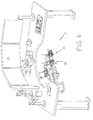
- FIG. 2 illustrates a perspective view of a workstation 100 that can be used in setting up automated movements for use by the robotic arms shown in the figures.
- workstation 100 comprises input devices 10 shown in FIG. 1 to control movement of the robotics arm, both actual and virtual.
- Workstation 100 may include a table (as shown) to which the input devices are secured as well as a series of display screens, any one or more of which can provide a graphical user interface (GUI) that can be used in setting up an automated movement for a given robotic arm.
- GUI graphical user interface
- one of the present systems can be configured to cause display screen 110 to display a GUI that may include one or more data entry elements (e.g., buttons, radio buttons, drop-down menus, tabs, slider bars, text entry fields, and the like) that allow a user to use any suitable input means (such as touching the screen, using a mouse, and/or using a keyboard, etc.) to perform any of a variety of functions, including to select elements in order to define and store one or more automated movements (e.g., by selecting two or more tool positions and orientations, such as a tool tip position and a tool axis orientation (see FIG.
- data entry elements e.g., buttons, radio buttons, drop-down menus, tabs, slider bars, text entry fields, and the like
- any suitable input means such as touching the screen, using a mouse, and/or using a keyboard, etc.
- FIG. 12 which shows an example of a longitudinal axis of a tool, which is also the axis (in the preferred embodiment) of the tool holders of the end effector of the robotic arm that is holding the tool, such that tool axis orientation may be determined from the end effector position, which may be known from the joint values of the robotic arm), select a robotic arm and a tool to use in defining the movement, select a stored automated movement for execution by a selected robotic arm (this is one manner of associating a robotic arm with a given automated movement), edit a stored automated movement, and delete a stored automated movement.
- the present computer systems can be configured to perform other functions discussed throughout this disclosure.
- FIGS. 3-10 are provided to illustrate various aspects of automated movements that may be programmed according to the present techniques.
- a medical (e.g., surgical, or more specifically microsurgical) procedure is shown being performed on a schematic representation 400 of a patient.
- a schematic representation of a tool exchange nurse 410 is shown positioned on one side of the patient, near the patient's head and the medical robotic system, and a schematic representation of an assisting surgeon 420 is shown positioned on the other side of the patient, near the patient's head and the medical robotic system.
- Left and right robotic arms 200L and 200R are shown secured to a mobile base station 150 (having a foot lever 152 that renders it position-lockable) to which a digitizing arm 160 (for use in physical registration of one or both robotic arms to an image or images of a portion of the patient) and a field camera 170 (via an adjustable stand) are also secured.
- a digitizing arm 160 for use in physical registration of one or both robotic arms to an image or images of a portion of the patient
- a field camera 170 via an adjustable stand
- Patient 400 is shown positioned on a patient support surface in the form of a top surface of an operating table 180, and the patient's head is secured using pins of a head clamp 190.
- Left robotic arm 200L is holding a tool (also characterizable as an instrument) 300L, which is depicted as a pair of forceps, and right robotic arm 200R is holding a tool 300R, which is depicted as a needle.
- the tools may be integrated with the robotic arms.
- the tools are shown inserted in the patient's head through an opening that represents a burr hole or craniotomy entry hole.
- FIGS. 5 and 6 show right tool 300R located outside of the patient's head and in a tool exchange location, which can correspond to a destination point of an automated movement programmable according to embodiments of the present techniques.
- tool exchange nurse 410 may decouple right tool 300R from right robotic arm 200R, and replace it with another tool that the nurse couples to the robotic arm.
- Left tool 300L is shown remaining in place in the patient's head.
- FIGS. 7 and 8 show right tool 300R located in the patient's head, while left tool 300L is positioned in a safe location outside of the patient's head.
- This safe location may satisfy one of the present proximity conditions that may serve as a prerequisite to executing an automated movement.
- One example proximity condition is one in which the tool tip must be outside of the patient's head.
- a surgeon may move left tool 300L to the location shown in FIGS. 7 and 8 when he or she desires to start an automated movement, such as an automated movement that will cause left robotic arm 200L to move tool 300L into a tool exchange position.
- the automated movement can proceed following the surgeon's depression and hold of button 16 on the relevant input device 10.
- FIG. 9 shows the result of execution of the commanded automated movement because left tool 300L is in a tool exchange position (such as one that can be the destination point for a given automated movement).
- FIG. 10 shows the result of execution of two automated movements, where both the tools are in tool exchange locations that can correspond to destination points for the automated movements.
- Some embodiments of the present automated movements may be used to move a manipulator from a microsurgical position, to a tool exchange position, and back again without requiring the operator to perform that motion using the relevant hand controller.
- Several automated movements can be pre-programmed and stored using embodiments of the present computer systems. Upon start up, the operator (e.g., a surgeon) would choose which of the preprogrammed moves he would like to have (e.g., as a tool exchange automated movement).
- the computer system may be configured to tie the selected automated movement to button 16 on the relevant hand controller to allow the operator to command the movement without going into the Automove GUI page (discussed and shown below), or having to take his hand off of the relevant hand controller.
- the present automated movements comprise two or more taught (e.g., user-defined or user-selected) points.
- a given automated movement comprises a start and an end (e.g., termination) point. This will define a motion that is a straight line between the two points. If a non-linear motion is desired based, for example, on a desire to avoid a potential obstacle, one or more intermediate (e.g., waypoints) can also be defined. The resulting path will then involve movement through each of the waypoints in between the start and end points.
- Certain embodiments of the present computer systems may be configured to perform some or all of the functions described below.
- Those of ordinary skill in the art having the benefit of this disclosure will be able to write code (machine readable instructions, which can be implemented through software, hardware, firmware, or a combination of any two or more of these) without undue experimentation for accomplishing the features and functions (including the graphical user interfaces) described below and shown in the figures.
- Automated movements may be created in the "Automove" page on the CSD GUI, shown for example in FIG. 12 .
- FIGS. 11-17 show examples of the states of the CSD GUI that can be displayed, for example, on display 110.
- the computer system can either be in simulation mode (see, e.g., FIG. 17 ), or fully configured for manipulator motion.
- Separate automated movements may be created for left and right robotic arms, such as those shown in FIGS. 3-10 , which can be identical or at least similar in construction, operation, and functionality to those disclosed in the '316 patent.
- the following sequence of steps may be followed, and the following functions performed, consistent with some embodiments of the present methods, devices, and systems (e.g., computer systems) to create, select, and execute an automated movement.
- a given automated movement may involve movement by one, some, or all of the joints of a given manipulator, including the base joint (e.g., the shoulder joint).
- the computer system mode may be set to "Microsurgery” on the GUI “Setup” page under the "Surgery Type” box on the "Mode Controls” tab, as shown in FIG. 11 .
- the computer system is configured, at this point, to show only grayed (unhighlighted) versions of the robotic arms on the GUI, indicating that neither has been powered on.
- the representations of the robotic arms on the screen are graphical (meaning they are not actual images of the arms), but the representations may be to scale, as they are in the present figures.
- the GUI may display a screen similar to what is shown in FIG. 12 , in which a graphical representation of a subject's (e.g., a patient's) head is shown (as a wire-frame sphere), with an indicator (e.g., a ball, which can be colored) as the center of the graphical head, along with the graphical representations of the robotic arms and the tools selected for each to give the user a view of their positions relative to the subject's head.
- a subject's e.g., a patient's
- an indicator e.g., a ball, which can be colored
- a user can select an arm ("Left Arm” or “Right Arm”) the user wishes to define a given automated movement for (see FIG. 12 ).
- the computer system may be configured such that, if the arms are powered (because, e.g., the On/Off button (see FIG. 11 ) has been set to "On” for those arms), the display will show the current position of the manipulators.
- a user may select a tool under the "Tool Select” drop-down menu under the "Mode Controls” tab shown in FIG. 13 to associate a particular tool with a selected robotic arm.
- a user may send a command to the computer system (which may be characterized as receiving the command) that results from movement of a given hand controller causing virtual movement on the GUI of the graphical representation of the associated robotic arm by pickling up the hand controller that corresponds to the selected robotic arm (e.g., right hand controller 10 for right robotic arm 200R), depressing the enable button (e.g., button 16, which may also be characterized as a stylus enable button), and moving the virtual manipulator via movement of the enabled hand controller to any desired location for a starting point of the desired automated movement.
- the computer system which may be characterized as receiving the command
- a user can send a command to the computer system to disengage the hand controller from the selected robotic arm such that any movement of that hand controller no longer causes virtual movement of the robotic arm (as reflected on the GUI) by depressing the same button (e.g., button 16) again.
- a user need not disable/disengage the hand controller at this time.
- a user can select (e.g., highlight by touching the screen) the "Start Point” entry and select the "Set Point” button to send a command to the computer system defining the starting location for the automated movement (see FIG. 13 ).
- the dataset that the computer systems receives as a result of this command may comprise data sufficient for the computer system to determine the (a) location in terms of X, Y and Z Cartesian coordinates of the tool tip in any suitable coordinate system (such as the coordinate system of the robotic arm, which may be mapped to image space (e.g., magnetic resonance imaging space) for the purpose of creating the virtual tool overlay shown in some of the figures (e.g., magnetic resonance imaging space), and (b) the orientation of the longitudinal axis of the tool (see FIG. 12 for a depiction of a such an axis).
- image space e.g., magnetic resonance imaging space
- FIG. 12 for a depiction of a such an axis
- the hand controller if disabled/disengaged, may be enabled as described above and used to move the virtual manipulator to any desired location.
- a user can, if he chooses, disable the hand controller as described above, and then under the "Teach" box on the "Mode Controls” tab select “Add” to create the waypoint, followed by selecting the "Set Point” button to send a command to the computer system defining the location of the desired waypoint in the automated movement. This can be repeated for each desired waypoint in the automated movement.
- the computer system may be configured such that after each waypoint is defined, a line on the screen is drawn between the new point and the previously defined point describing the programmed path (see FIG. 14 ).
- a user can define the end or destination location for the automated movement in similar fashion. For example, the user may ensure that the hand controller is enabled, move the virtual manipulator to the desired location for the destination point, disable the hand controller if desired, and under the "Teach" box on the "Mode Controls" tab select (e.g., highlight by touching the screen) the "Destination Point” entry and select the "Set Point” button to send a command to the computer system defining the destination point for the automated movement.
- the computer system may be configured to cause the CSD screen to then show one or more line segments between the starting point, through each of the defined waypoints (if any), and to the destination point (see FIGs. 14 and 15 ).
- the computer system may be configured such that, after the automated movement has been defined as described above, the automated movement may be simulated to allow the operator to verify that the motion as programmed is as intended. To make such a verification, the virtual manipulator as shown on the GUI should be within a valid range (e.g., it should satisfy one of the present proximity conditions) of the start or end point of the selected automated movement.
- a user may press the "Simulate” button in the "Teach” box of the "Mode Controls” tab (see FIG. 15 ), which will cause the virtual manipulator to move from one end of the automated movement to the other.
- the computer system may be configured to show a highlighted version of the virtual manipulator move overlaying an unhighlighted version of the manipulator that remains in the pose of the real manipulator.
- the computer system may be configured to detect collisions in this simulation mode. Further, it may be configured to display a suitable error message if a collision or collisions are detected that would be caused by execution of the automated movement, or if movement through any sections along the path would exceed a robotic arm joint limit or velocity limit.
- the computer system may be configured such that an entire automated movement may not be valid even though the virtual manipulator can reach the start and end points because the actual manipulator may have to pass through an area that it cannot physically reach. In such an instance, the automated movement may be edited as described below, and a simulation of the same run again.
- the computer system may be configured such that a user may program (and store) any number of automated movements, but only one of the automated movements can be selected for execution (e.g., as a tool exchange automated movement) by a given manipulator.
- a user may program (and store) any number of automated movements, but only one of the automated movements can be selected for execution (e.g., as a tool exchange automated movement) by a given manipulator.
- the user can highlight the name of that automated movement in the list under the "Automove” box, press the "Load” button, and then check the "Set As Tool Exchg" box. See FIG. 16 .
- the computer system may be configured to save multiple automated movements independently for the left and right robotic arms.
- the computer system may be configured such that, to save an automated movement after it is defined (and after it is verified, if verification is performed), a user may select the text entry field under "Automove Name” in the "Automove” box of the "Mode Controls” tab, causing an onscreen keyboard to appear (not shown). A user may type a name for the automated movement just defined, and then press the "OK” button that appears with the keyboard. Next, the user may hit the "Save” button on the GUI in the "Automove” box of the "Mode Controls” tab (see FIG. 16 ). The computer system may be configured to provide a status message (see the box at the top of FIGS. 13-16 next to the ACK button) that indicates whether the automated movement was saved without errors.
- the computer system may be configured such that an automated movement may be loaded by a user after it is saved.
- a list box contains all of the previously defined automated movements for the selected robotic arm under the "Automove” box of the "Mode Controls" tab in the "Automove” settings page.
- a user can highlight the automated movement he wishes to load and then press the "Load” button. If the user wishes to use this loaded automated movement as the tool exchange motion for the selected robotic arm, he can do so by following the steps described above.
- the user wishes to edit or replace the loaded automated movement, he may remove a point or points (up to all of them, allowing the user to start over) in the automated movement by highlighting the relevant point in the list of points shown in the "Teach" box and then pressing "Remove,” and add a point or points to the automated movement using, for example, the technique discussed above.
- a user can save the edits by pushing the "Save” button in the "Automove” box. See FIG. 16 .
- the computer system may be configured to ask the user to confirm, through a pop-up box, that the "Save” button be pressed a second time to confirm the overwrite.
- the computer system may be configured such that the user can then check the status message to ensure that the edited/new automated movement was saved without errors.
- a user may delete a saved automated movement by clicking the "Remove” button instead of the "Load” button after highlighting the name of the automated movement in the list box. See FIG. 16 .
- the present computer systems may be configured to execute automated movements in multiple ways. For example, a command may be sent from either the GUI or from a hand controller.
- a user may: select a robotic arm (as described above), load a saved automated movement (as described above) or have finished the creation of an automated movement (as described above), ensure that the robotic arm is powered (as described above) and associated with the automated movement that was loaded or just created, ensure that the associated robotic arm is near the start or end point of the automated movement, and select (e.g., press) the "Execute” button in the bottom right-hand part of the GUI on the "Mode Controls" tab.
- the robotic arm executes the loaded/finished automated movement.
- the computer system may be configured such that pressing the "Execute” button again reverses the previously executed automated movement.
- the computer system may be configured to require that the enable button on the hand controller be depressed and held after the "Execute" button is pressed, thus better ensuring that an operator is holding the hand controller if actual manipulator movement is occurring.
- the computer system may be configured such that depressing the enable button again will cause the motion to stop, and a subsequent depression and hold will cause the motion to reverse.
- a user may load an automated movement (as described above) and specify it as the tool exchange motion (as described above); designate microsurgery mode (as described above); enter a master-slave mode by selected (e.g., pressing) the "Master/Slave" button at the left of the GUI (see, e.g., FIG. 17 ); using the relevant input device, move the robotic arm to a location near the start or end point of the tool exchange automated movement; and apply a sharp click followed by a sustained (e.g., two second) hold of the button on the input device (e.g., button 16 on stylus 12 of input device 10), where the computer system is configured to recognize the extended bold as a command that the operator wishes to perform a tool exchange.
- a sustained e.g., two second
- a proximity condition may involve a check of whether the tip (e.g., the distal tip) of a tool held by the manipulator is either sufficiently close to the start point or to the end point of the automated movement.
- the computer system may be configured such that, if not, a sphere for each programmed zone will be shown on the CSD GUI, thus identifying the acceptable boundaries. See FIG. 18 . A user can then use the CSD GUI to move the robotic arm such that the tool tip is within a boundary and restart the automated movement in the manner described above.
- the computer system may be configured such that releasing the stylus enable button before the automated movement begins causes the automated movement not to execute. Otherwise, when the automated movement begins, the user can release the enable button, and motion will continue through the path to the destination point.
- the computer system may be configured such that the automated movement may be reversed once it has completed in the forward direction by a press and hold of the enable button on the input device in the same manner that started the automated movement. One the reverse automated movement starts, the button may be released and the motion will start and continue until the reverse path has completed.
- the computer system also may be configured to allow a user to interrupt an automated movement at any time during its execution by briefly pressing the hand controller enable button. A quick press of the same button will cause the robotic arm to stop.
- Another click and hold will move the tool back to the start point for the movement, and during that return if the user desires to continue with the original movement, he may press the enable button yet again to cause the robotic arm to stop. Another click and hold will cause arm to re-continue the original, interrupted motion.
- a tool exchange nurse may decouple the robotic arm from its current tool at the tool exchange location (e.g., the destination point for the automated movement), couple a new tool to the robotic arm, and scan the new tool using a data matrix reader either while the robotic arm is stationary or in motion.
- the computer system may also be configured to support scanning two tools held in the two arms.
- the computer system may be configured to provide, as in the disclosed embodiment, three speeds at which an automated movement can be executed: slow, medium and fast.
- the computer system may also be configured, as in the disclosed embodiment, such that the chosen speed applies to each automated movement subsequently selected for execution until a speed change selection is made.
- a user may select the "User Settings” tab of the Automove page, as shown in FIG. 17 .
- the user may select the desired speed ("Fast,” “Med,” or “Slow") using the radio buttons beneath the "Options” box of this tab.
- one or both robotic arms may be registered with one or more two-dimensional images (e.g., the 2D images of a 3D dataset of images taken with a 3D imaging modality, such as a magnetic resonance imaging (MRI) machine) of the subject (e.g., a patient).
- MRI magnetic resonance imaging
- automated movements may be created and executed without performing such registration, though safety checks such as collision with no-go zones (defining, for example, the patient's head boundary or structures near the operating site, such as the microscope, the bore of the MRI machine, cameras, etc.) cannot otherwise be performed.
- a suitable technique for accomplishing such registration through a process that involves both physical registration and registration involving image space is disclosed in copending International Application No.PCT/ US08/60538 .
- software can be written for achieving the functions described above, and may comprise three pieces: 3D visualization, path generation, and path execution.
- Visualization of a given virtual robotic arm on a suitable GUI can be based on the use of virtual reality modeling language (VRML) models based on engineering computer-aided design (CAD) models of the robotic arm mechanical components, rendered with OpenGL® graphics.
- VRML virtual reality modeling language
- CAD engineering computer-aided design
- the VRML models can be compiled into OpenGL call lists and positioned in 3D space using robot kinematics calculations.
- the kinematics routines provide the position and orientation (x, y, z, pitch, yaw, roll) of each robotic arm segment given either the arm joint angles or end-effector pose.
- a given automated movement may comprise a list of two or more user-defined points, each describing a complete Cartesian tool pose (x, y, z, pitch, roll, yaw). These points form the basis for generating an automated movement path, which can interpolate intermediate points along straight-line segments between each pair of user-defined points.
- the intermediate path points (which are those that are not specifically defined by a user) can be spaced at intervals that correspond to ten milliseconds of motion and may be represented in joint space.
- each point along the path may comprise a set of six joint angles (Shoulder Yaw, Shoulder Roll, Elbow Yaw, Elbow Roll, Wrist Pitch, Tool Roll) when the automated movement is to be executed and was set up using a six-degree of freedom robotic arm, such as those shown in the figures and disclosed in the '316 patent.
- each set of joint angles along the path can be obtained from a linearly interpolated Cartesian pose through inverse kinematics.
- Each point along the calculated path can be checked for collisions against known obstacles (microscope, patient head region, surgical table) and the other arm (if present).
- the collision checks which can be performed at a frequency of 100 Hz per robotic arm during operation but even more frequently during calculation of an automated movement path, can be based on the use of any suitable collision detection algorithm available to those of ordinary skill in the art, such as VCollide, an efficient polygon interference algorithm designed to operate on large numbers of polygonal objects.
- Vcollide makes no assumptions about input structure and works on arbitrary models, also known as "polygon soups.” Vcollide uses a three-stage collision detection architecture characterized by an N-body test that finds possibly colliding pairs of objects, a hierarchical oriented bounding box test that finds possibly colliding pairs of triangles, and an exact test that determines whether or not a pair of triangles actually overlaps.
- the closed-form absolute kinematic equations can be used where sufficient details of the physical structure of the robotic arm-e.g., dimensions, effective link lengths between joints, and the like-are known and permit a closed form solution to exist.
- the closed-form absolute kinematic equations can be used when the wrist yaw joint (seventh joint) of the robotic arm is removed, such as to provide a closed form solution.
- Execution of an automated movement involves commanding the robot hardware to move to each successive point along the automated movement path at ten millisecond (ms) intervals. Because the path is represented in joint space there is no need to re-calculate inverse kinematics. During execution, collision checks may be repeated for safety in case the position of scene objects has changed or the robotic arm does not exactly follow the commanded path. To achieve smooth motion, the point one ahead of the intended target point is the one actually commanded to the joint motion controller, with a commanded time interval of twenty ms. After ten ms have elapsed, the destination is altered with a new destination point which is again twenty ms ahead.
- ms millisecond
- Embodiments of the present techniques may be coded as software stored on any suitable computer readable media (e.g., tangible computer readable media) to form the present devices, such as any suitable form of memory or data storage device, including but not limited to hard drive media, optical media, RAM, SRAM, DRAM, SDRAM, ROM, EPROM, EEPROM, tape media, cartridge media, flash memory, memory stick, and/or the like.
- Tangible computer readable media includes any physical medium that can store or transfer information. Such embodiments may be characterized as tangible computer readable media having (or encoded with) computer executable (e.g., machine readable) instructions for performing certain step(s).
- tangible computer readable medium does not include wireless transmission media, such as carrier waves.
- the term "computer readable medium,” however, does cover wireless transmission media, and some embodiments of the present methods may include wireless transmission media carrying the computer readable instructions described above.
- the software can be written according to any technique known in the art. For instance, the software may be written in any one or more computer languages (e.g., ASSEMBLY, PASCAL, FORTRAN, BASIC, C, C++, C#, JAVA, Perl, Python) or using scientific packages like, but not limited to, Matlab®, R, S-plus®, and SAS®.
- the code may be to enable it to be compiled on all common platforms (e.g., Microsoft®, Linux®, Apple Macintosh® OS X, Unix®).
- the software may include a GUI, which may provide a user with a more intuitive feel when running the software.
- Different fields may be accessible by screen touching, a mouse and/or keyboard.
- Alarms, cues, and the like may be done via pop-up windows, audible alerts, or any other techniques known in the art.
- Some (up to all) of the functions described above may be implemented using a computer having a processor (e.g., one or more integrated circuits) programmed with firmware and/or running software. Some (up to all) of the functions described above may be implemented using a distributed computing environment, which is one example of a computer system. In a distributed computing environment, multiple computers may be used, such as those connected by any suitable number of connection mediums (e.g., a local area network (LAN), a wide area network (WAN), or other computer networks, including but not limited to Ethernets, enterprise-wide computer networks, intranets and the Internet, and the connections between computers can be wired or wireless). Servers and user terminals can be part of a given computer system.
- connection mediums e.g., a local area network (LAN), a wide area network (WAN), or other computer networks, including but not limited to Ethernets, enterprise-wide computer networks, intranets and the Internet, and the connections between computers can be wired or wireless.
- Servers and user terminals can be part of
- embodiments of suitable computer systems may be implemented on application specific integrated circuits (ASICs) or very large scale integrated (VLSI) circuits, and further (or alternatively) may be configured to use virtualization of resources, virtual computing, and/or cloud computing to achieve the specified functions.
- ASICs application specific integrated circuits
- VLSI very large scale integrated circuits
- persons of ordinary skill in the art may utilize any number of suitable structures capable of executing logical operations in order to achieve the functions described above in a computer system consistent with this disclosure.
Landscapes
- Engineering & Computer Science (AREA)
- Health & Medical Sciences (AREA)
- Robotics (AREA)
- Life Sciences & Earth Sciences (AREA)
- Surgery (AREA)
- Medical Informatics (AREA)
- Biomedical Technology (AREA)
- Heart & Thoracic Surgery (AREA)
- Nuclear Medicine, Radiotherapy & Molecular Imaging (AREA)
- Molecular Biology (AREA)
- Animal Behavior & Ethology (AREA)
- General Health & Medical Sciences (AREA)
- Public Health (AREA)
- Veterinary Medicine (AREA)
- Mechanical Engineering (AREA)
- Manipulator (AREA)
Claims (25)
- Procédé exécuté par ordinateur permettant le mouvement automatisé d'un bras robotisé d'un robot de chirurgie, le bras robotisé étant configuré pour se déplacer dans un mode d'auto-déplacement et dans un mode maître-esclave, le procédé comprenant au moins les étapes suivantes de:(a) réception d'au moins une indication d'au moins un mouvement automatisé d'un bras robotisé, le mouvement automatisé du bras robotisé comprenant une position de départ programmée pour un outil fonctionnellement associé avec un bras robotisé, et une position finale programmée pour l'outil;(b) la réception des coordonnées d'une position de l'outil;(c) la réception d'une instruction pour exécuter le mouvement automatisé du bras robotisé; et soit(d) l'exécution du mouvement automatisé du bras robotisé si la condition de proximité est satisfaite, la condition de proximité se rapportant à la position de l'outil relativement à la position de départ programmée dans laquelle, l'exécution du mouvement automatisé du bras robotisé permet à l'outil de se déplacer jusqu' à la position finale programmée, ou si la condition de proximité n'est pas satisfaite, la génération d'une sortie comprenant une représentation graphique identifiant une limite dans laquelle la condition de proximité serait satisfaite, permettant ainsi un mouvement guidé par l'utilisateur du bras robotisé, en mode maître-esclave, de sorte que la condition de proximité soit satisfaite.
- Procédé de la revendication 1, dans lequel la position de départ programmée est définie relativement par rapport à la pointe de l'outil, et la condition de proximité se rapporte à la position de la pointe de l'outil relativement à la position de départ programmée.
- Procédé selon la revendication 1 ou 2, dans lequel l'actionnement d'une touche ou d'un levier se trouvant sur la commande manuelle principale génère l'instruction en étape (c).
- Procédé de l'une quelconque des revendications 1 à 3, comprenant au moins les étapes suivantes:(e) de réception d'une instruction pour exécuter un deuxième mouvement automatisé du bras robotisé qui comprend un déplacement du bras robotisé pour s'éloigner de la position finale programmée; et(f) de l'exécution d'un deuxième mouvement automatisé du bras robotisé si une deuxième condition de proximité est satisfaite, la deuxième condition de proximité se rapportant à la position de l'outil par rapport à la position finale programmée dans laquelle l'exécution du mouvement automatisé permet à l'outil de s'éloigner de la position finale programmée.
- Procédé de l'une quelconque des revendications 1 à 4, comprenant au moins les étapes suivantes:de réception d'une instruction pour interrompre le mouvement automatisé du bras robotisé; etd'arrêt du mouvement automatisé du bras robotisé.
- Procédé de l'une quelconque des revendications 1 à 5, dans lequel la position finale programmée correspond à un emplacement de changement d'outil.
- Procédé de l'une quelconque des revendications 1 à 6, dans lequel
l'étape (a) comprend la réception d'indications de multiples mouvements automatisés du bras robotisé, chaque mouvement automatisé du bras robotisé comprenant au moins une position de départ de l'outil et une position finale programmée de l'outil ; et
l'étape (c) comprend la réception d'une instruction pour exécuter l'un des multiples mouvements automatisés du bras robotisé. - Procédé de la revendication 7, dans lequel le procédé est destiné à un mouvement automatisé d'un bras robotisé d'un robot de chirurgie comportant deux bras ou plus , chaque bras robotisé étant configuré pour le mouvement dans un mode auto-déplacement et dans un mode maître-esclave, et dans lequel le procédé comprend également:la réception d'une commande pour la sélection d'un des bras robotisés pour l'exécution du mouvement automatisé du bras robotisé.
- Procédé selon les revendications 7 ou 8, comprenant également les étapes:l'affichage d'une interface graphique pour l'utilisateur ayant un ou plusieurs éléments de saisie de données qui permettent au moins ce qui suit :(i) la définition de chaque mouvement automatisé du bras robotisé en définissant au moins la position de départ programmée et la position finale programmée pour chaque mouvement automatisé du bras robotisé, et(ii) la sélection d'un bras robotisé d'un robot de chirurgie pour exécuter un ou plusieurs des multiples mouvements automatisés du bras robotisé.
- Procédé de l'une quelconque des revendications 1 à 9, comprenant:la définition de la position de départ programmée et de la position finale programmée en indiquant un premier ensemble de données pour la position de départ programmée et en indiquant un deuxième ensemble de données pour la position finale programmée.
- Procédé selon la revendication 10, dans lequel l'outil fonctionnellement associé avec le bras robotisé comporte un axe longitudinal et le premier ensemble de données et le deuxième ensemble de données comprennent des données suffisantes à la détermination d'une position de la pointe de l'outil et l'orientation de l'axe longitudinal de l'outil.
- Procédé selon la revendication 11, dans lequel l'exécution du mouvement automatisé du bras robotisé comprend le mouvement de l'outil le long d'un axe qui ne coïncide pas avec l'axe longitudinal de l'outil.
- Procédé de l'une quelconque des revendications 1 à 12, comprenant au moins les étapes suivantes:la réception d'une commande pour exécuter une inversion du mouvement automatisé après l'achèvement de l'exécution du mouvement automatisé; etl'exécution de l'inverse du mouvement automatisé de sorte que le bras robotisé s'éloigne de la position finale programmée vers la position de départ programmée.
- Procédé selon la revendication 9, dans lequel un ou plusieurs éléments de saisie de données de l'interface graphique de l'utilisateur permet également au moins ce qui suit:la sélection d'un mode de simulation permettant de définir les multiples mouvements automatisés du bras robotisé;et le procédé comprenant également au moins les étapes suivantes:l'affichage d'une représentation graphique du bras robotisé sur l'interface graphique de l'utilisateur, etle déplacement de la représentation graphique en réponse au mouvement d'un dispositif de saisie sans également entraîner le mouvement réel du bras robotisé.
- Procédé selon les revendications 9 ou 14, dans lequel un ou plusieurs éléments de saisie de données de l'interface graphique de l'utilisateur permet également au moins ce qui suit:la sélection de l'outil devant être fonctionnellement associé avec le bras robotisé choisi.
- Procédé selon les revendications 9 ou 14, comprenant également au moins les étapes suivantes:l'affichage d'une représentation graphique d'un ou de deux bras robotisés du robot de chirurgie sur l'interface graphique de l'utilisateur;la réception d'une commande provenant du dispositif de saisie associé avec un bras robotisé donné; etle déplacement de la représentation graphique du bras robotisé sur l'interface graphique de l'utilisateur en réponse à une manipulation du dispositif de saisie, de sorte que l'interface graphique de l'utilisateur affiche l'effet de la manipulation du dispositif de saisie sur le mouvement de ce bras robotisé.
- Procédé selon la revendication 16, comprenant également au moins l' étape suivante :l'affichage d'une représentation graphique de la tête d'un sujet sur l'interface graphique de l'utilisateur.
- Procédé selon les revendications 16 ou 17, comprenant également au moins les étapes suivantes:la réception d'une commande de désactivation provenant du dispositif de saisie associé avec un bras robotisé donné; etle découplage de la manipulation du dispositif de saisie et du mouvement de la représentation graphique de ce bras robotisé sur l'interface graphique de l'utilisateur.
- Procédé de l'une quelconque des revendications 9, 14, 15, 16, 17 ou 18, comprenant au moins l'étape suivante :l'affichage d'un chemin défini par la position de départ programmée et la position finale programmée du mouvement automatisé du bras robotisé sur l'interface graphique de l'utilisateur.
- Procédé selon la revendication 19, dans lequel un ou plusieurs éléments de saisie de données de l'interface graphique de l'utilisateur permet également au moins ce qui suit:la définition d'une ou de plusieurs positions intermédiaires entre la position de départ programmée et la position finale programmée d'un mouvement automatisé du bras robotisé ;et dans lequel le procédé comprend également au moins l'étape suivante:l'affichage d'un chemin défini par la position de départ programmée, l'une ou plusieurs positions intermédiaires et la position finale programmée du mouvement automatisé du bras robotisé.
- Procédé selon l'une quelconque des revendications 1 à 20, dans lequel la condition de proximité est satisfaite lorsque l'outil est dans une région prédéfinie, la région prédéfinie entourant le point de départ programmé.
- Procédé selon la revendication 21, dans lequel la région prédéfinie correspond à un emplacement externe par rapport au corps du patient.
- Procédé selon l'une quelconque des revendications 1 à 19, 21 ou 22, dans lequel le mouvement automatisé du bras robotisé comprend également un ou plusieurs points de repère entre la position de début programmée et la position finale programmée.
- Support lisible par ordinateur qui contient des instructions lisibles par un appareil permettant de réaliser au moins les étapes décrites dans l'une quelconque des revendications 1 à 23.
- Système informatique configuré pour commander le mouvement d'un bras robotisé d'un robot de chirurgie, le système comprenant:un bras robotisé d'un robot de chirurgie, le bras robotisé étant configuré pour se déplacer dans un mode d'auto-déplacement et dans un mode maître-esclave,un ordinateur fonctionnellement associé avec le robot de chirurgie et configuré pour réaliser le procédé permettant le mouvement automatisé d'un bras robotisé selon l'une quelconque des revendications 1 à 23,un ou plusieurs dispositifs de saisie fonctionnellement associés avec l'ordinateur pour la saisie de commandes se rapportant au moins au mouvement automatisé du bras robotisé, etune interface utilisateur graphique fonctionnellement associée avec l'ordinateur pour l'affichage d'au moins une représentation graphique d'un bras robotisé et des données se rapportant au mouvement du bras robotisé.
Applications Claiming Priority (2)
| Application Number | Priority Date | Filing Date | Title |
|---|---|---|---|
| US91214207P | 2007-04-16 | 2007-04-16 | |
| PCT/IB2008/003351 WO2009044287A2 (fr) | 2007-04-16 | 2008-04-16 | Méthodes, dispositifs et systèmes de mouvements automatisés concernant des robots médicaux |
Publications (3)
| Publication Number | Publication Date |
|---|---|
| EP2142133A2 EP2142133A2 (fr) | 2010-01-13 |
| EP2142133A4 EP2142133A4 (fr) | 2011-02-23 |
| EP2142133B1 true EP2142133B1 (fr) | 2012-10-10 |
Family
ID=40526771
Family Applications (1)
| Application Number | Title | Priority Date | Filing Date |
|---|---|---|---|
| EP08835600A Not-in-force EP2142133B1 (fr) | 2007-04-16 | 2008-04-16 | Méthodes, dispositifs et systèmes de mouvements automatisés concernant des robots médicaux |
Country Status (6)
| Country | Link |
|---|---|
| US (1) | US8738181B2 (fr) |
| EP (1) | EP2142133B1 (fr) |
| JP (2) | JP2010524547A (fr) |
| CA (1) | CA2684472C (fr) |
| IL (1) | IL201605A0 (fr) |
| WO (1) | WO2009044287A2 (fr) |
Cited By (1)
| Publication number | Priority date | Publication date | Assignee | Title |
|---|---|---|---|---|
| EP3463162A4 (fr) * | 2016-06-03 | 2020-06-24 | Covidien LP | Systèmes, procédés et produits de programme lisibles par ordinateur pour commander un manipulateur commandé par robot |
Families Citing this family (258)
| Publication number | Priority date | Publication date | Assignee | Title |
|---|---|---|---|---|
| US8944070B2 (en) | 1999-04-07 | 2015-02-03 | Intuitive Surgical Operations, Inc. | Non-force reflecting method for providing tool force information to a user of a telesurgical system |
| US9789608B2 (en) | 2006-06-29 | 2017-10-17 | Intuitive Surgical Operations, Inc. | Synthetic representation of a surgical robot |
| US7571027B2 (en) * | 2005-05-31 | 2009-08-04 | The Boeing Company | Kinematic singular point compensation systems and methods |
| US8219178B2 (en) | 2007-02-16 | 2012-07-10 | Catholic Healthcare West | Method and system for performing invasive medical procedures using a surgical robot |
| US10357184B2 (en) | 2012-06-21 | 2019-07-23 | Globus Medical, Inc. | Surgical tool systems and method |
| US10653497B2 (en) | 2006-02-16 | 2020-05-19 | Globus Medical, Inc. | Surgical tool systems and methods |
| US10893912B2 (en) | 2006-02-16 | 2021-01-19 | Globus Medical Inc. | Surgical tool systems and methods |
| US20080064927A1 (en) | 2006-06-13 | 2008-03-13 | Intuitive Surgical, Inc. | Minimally invasrive surgery guide tube |
| US8560047B2 (en) | 2006-06-16 | 2013-10-15 | Board Of Regents Of The University Of Nebraska | Method and apparatus for computer aided surgery |
| US20090192523A1 (en) | 2006-06-29 | 2009-07-30 | Intuitive Surgical, Inc. | Synthetic representation of a surgical instrument |
| US12357400B2 (en) | 2006-06-29 | 2025-07-15 | Intuitive Surgical Operations, Inc. | Synthetic representation of a surgical robot |
| US9718190B2 (en) | 2006-06-29 | 2017-08-01 | Intuitive Surgical Operations, Inc. | Tool position and identification indicator displayed in a boundary area of a computer display screen |
| US10258425B2 (en) | 2008-06-27 | 2019-04-16 | Intuitive Surgical Operations, Inc. | Medical robotic system providing an auxiliary view of articulatable instruments extending out of a distal end of an entry guide |
| US10008017B2 (en) | 2006-06-29 | 2018-06-26 | Intuitive Surgical Operations, Inc. | Rendering tool information as graphic overlays on displayed images of tools |
| US9469034B2 (en) | 2007-06-13 | 2016-10-18 | Intuitive Surgical Operations, Inc. | Method and system for switching modes of a robotic system |
| US9138129B2 (en) | 2007-06-13 | 2015-09-22 | Intuitive Surgical Operations, Inc. | Method and system for moving a plurality of articulated instruments in tandem back towards an entry guide |
| US9084623B2 (en) * | 2009-08-15 | 2015-07-21 | Intuitive Surgical Operations, Inc. | Controller assisted reconfiguration of an articulated instrument during movement into and out of an entry guide |
| US8620473B2 (en) | 2007-06-13 | 2013-12-31 | Intuitive Surgical Operations, Inc. | Medical robotic system with coupled control modes |
| US9089256B2 (en) | 2008-06-27 | 2015-07-28 | Intuitive Surgical Operations, Inc. | Medical robotic system providing an auxiliary view including range of motion limitations for articulatable instruments extending out of a distal end of an entry guide |
| US8864652B2 (en) | 2008-06-27 | 2014-10-21 | Intuitive Surgical Operations, Inc. | Medical robotic system providing computer generated auxiliary views of a camera instrument for controlling the positioning and orienting of its tip |
| US12239396B2 (en) | 2008-06-27 | 2025-03-04 | Intuitive Surgical Operations, Inc. | Medical robotic system providing an auxiliary view including range of motion limitations for articulatable instruments extending out of a distal end of an entry guide |
| US8315720B2 (en) * | 2008-09-26 | 2012-11-20 | Intuitive Surgical Operations, Inc. | Method for graphically providing continuous change of state directions to a user of a medical robotic system |
| US8345004B1 (en) * | 2009-03-06 | 2013-01-01 | Pixar | Methods and apparatus for differentially controlling degrees of freedom of an object |
| US12266040B2 (en) | 2009-03-31 | 2025-04-01 | Intuitive Surgical Operations, Inc. | Rendering tool information as graphic overlays on displayed images of tools |
| US9492927B2 (en) | 2009-08-15 | 2016-11-15 | Intuitive Surgical Operations, Inc. | Application of force feedback on an input device to urge its operator to command an articulated instrument to a preferred pose |
| US8918211B2 (en) | 2010-02-12 | 2014-12-23 | Intuitive Surgical Operations, Inc. | Medical robotic system providing sensory feedback indicating a difference between a commanded state and a preferred pose of an articulated instrument |
| US9643316B2 (en) * | 2009-10-27 | 2017-05-09 | Battelle Memorial Institute | Semi-autonomous multi-use robot system and method of operation |
| US9888973B2 (en) * | 2010-03-31 | 2018-02-13 | St. Jude Medical, Atrial Fibrillation Division, Inc. | Intuitive user interface control for remote catheter navigation and 3D mapping and visualization systems |
| KR101598773B1 (ko) * | 2010-10-21 | 2016-03-15 | (주)미래컴퍼니 | 수술용 로봇의 움직임 제어/보상 방법 및 장치 |
| KR101891138B1 (ko) * | 2010-11-11 | 2018-08-23 | 더 존스 홉킨스 유니버시티 | 인간-기계 협력 로봇 시스템 |
| US9921712B2 (en) | 2010-12-29 | 2018-03-20 | Mako Surgical Corp. | System and method for providing substantially stable control of a surgical tool |
| US9119655B2 (en) | 2012-08-03 | 2015-09-01 | Stryker Corporation | Surgical manipulator capable of controlling a surgical instrument in multiple modes |
| WO2012131660A1 (fr) | 2011-04-01 | 2012-10-04 | Ecole Polytechnique Federale De Lausanne (Epfl) | Système robotisé et procédé pour chirurgie rachidienne et autre |
| US11911117B2 (en) | 2011-06-27 | 2024-02-27 | Board Of Regents Of The University Of Nebraska | On-board tool tracking system and methods of computer assisted surgery |
| US9498231B2 (en) | 2011-06-27 | 2016-11-22 | Board Of Regents Of The University Of Nebraska | On-board tool tracking system and methods of computer assisted surgery |
| WO2013052187A2 (fr) | 2011-06-27 | 2013-04-11 | Board Of Regents Of The University Of Nebraska | Système de suivi d'outil intégré et procédés de chirurgie assistée par ordinateur |
| US9387048B2 (en) | 2011-10-14 | 2016-07-12 | Intuitive Surgical Operations, Inc. | Catheter sensor systems |
| US20130303944A1 (en) | 2012-05-14 | 2013-11-14 | Intuitive Surgical Operations, Inc. | Off-axis electromagnetic sensor |
| US9452276B2 (en) | 2011-10-14 | 2016-09-27 | Intuitive Surgical Operations, Inc. | Catheter with removable vision probe |
| US10238837B2 (en) | 2011-10-14 | 2019-03-26 | Intuitive Surgical Operations, Inc. | Catheters with control modes for interchangeable probes |
| AU2012359758A1 (en) | 2012-01-31 | 2013-09-19 | Tomy Company, Ltd. | Robot toy |
| DE102012103031A1 (de) * | 2012-04-05 | 2013-10-10 | Reis Group Holding Gmbh & Co. Kg | Verfahren zur Bedienung eines Industrieroboters |
| DE102012103032B3 (de) * | 2012-04-05 | 2013-07-04 | Reis Group Holding Gmbh & Co. Kg | Verfahren zur Bedienung eines Industrieroboters |
| KR102366082B1 (ko) | 2012-06-01 | 2022-02-23 | 인튜어티브 서지컬 오퍼레이션즈 인코포레이티드 | 멀티포트 수술 로봇 시스템 구조 |
| US12594001B2 (en) | 2012-06-21 | 2026-04-07 | Globus Medical, Inc. | Apparatus for recording probe movement |
| US11317971B2 (en) | 2012-06-21 | 2022-05-03 | Globus Medical, Inc. | Systems and methods related to robotic guidance in surgery |
| US12310683B2 (en) | 2012-06-21 | 2025-05-27 | Globus Medical, Inc. | Surgical tool systems and method |
| US11589771B2 (en) | 2012-06-21 | 2023-02-28 | Globus Medical Inc. | Method for recording probe movement and determining an extent of matter removed |
| US10799298B2 (en) | 2012-06-21 | 2020-10-13 | Globus Medical Inc. | Robotic fluoroscopic navigation |
| US11974822B2 (en) | 2012-06-21 | 2024-05-07 | Globus Medical Inc. | Method for a surveillance marker in robotic-assisted surgery |
| US11963755B2 (en) | 2012-06-21 | 2024-04-23 | Globus Medical Inc. | Apparatus for recording probe movement |
| US12446981B2 (en) | 2012-06-21 | 2025-10-21 | Globus Medical, Inc. | System and method for surgical tool insertion using multiaxis force and moment feedback |
| US11045267B2 (en) | 2012-06-21 | 2021-06-29 | Globus Medical, Inc. | Surgical robotic automation with tracking markers |
| US10350013B2 (en) | 2012-06-21 | 2019-07-16 | Globus Medical, Inc. | Surgical tool systems and methods |
| US11793570B2 (en) | 2012-06-21 | 2023-10-24 | Globus Medical Inc. | Surgical robotic automation with tracking markers |
| US20170258535A1 (en) * | 2012-06-21 | 2017-09-14 | Globus Medical, Inc. | Surgical robotic automation with tracking markers |
| US11607149B2 (en) | 2012-06-21 | 2023-03-21 | Globus Medical Inc. | Surgical tool systems and method |
| US10646280B2 (en) | 2012-06-21 | 2020-05-12 | Globus Medical, Inc. | System and method for surgical tool insertion using multiaxis force and moment feedback |
| US11116576B2 (en) | 2012-06-21 | 2021-09-14 | Globus Medical Inc. | Dynamic reference arrays and methods of use |
| US11896446B2 (en) | 2012-06-21 | 2024-02-13 | Globus Medical, Inc | Surgical robotic automation with tracking markers |
| US12220120B2 (en) | 2012-06-21 | 2025-02-11 | Globus Medical, Inc. | Surgical robotic system with retractor |
| US11399900B2 (en) | 2012-06-21 | 2022-08-02 | Globus Medical, Inc. | Robotic systems providing co-registration using natural fiducials and related methods |
| US11298196B2 (en) | 2012-06-21 | 2022-04-12 | Globus Medical Inc. | Surgical robotic automation with tracking markers and controlled tool advancement |
| US10624710B2 (en) | 2012-06-21 | 2020-04-21 | Globus Medical, Inc. | System and method for measuring depth of instrumentation |
| US11864839B2 (en) | 2012-06-21 | 2024-01-09 | Globus Medical Inc. | Methods of adjusting a virtual implant and related surgical navigation systems |
| US11857149B2 (en) | 2012-06-21 | 2024-01-02 | Globus Medical, Inc. | Surgical robotic systems with target trajectory deviation monitoring and related methods |
| US11857266B2 (en) | 2012-06-21 | 2024-01-02 | Globus Medical, Inc. | System for a surveillance marker in robotic-assisted surgery |
| US12465433B2 (en) | 2012-06-21 | 2025-11-11 | Globus Medical Inc. | Methods of adjusting a virtual implant and related surgical navigation systems |
| US10758315B2 (en) | 2012-06-21 | 2020-09-01 | Globus Medical Inc. | Method and system for improving 2D-3D registration convergence |
| US10874466B2 (en) | 2012-06-21 | 2020-12-29 | Globus Medical, Inc. | System and method for surgical tool insertion using multiaxis force and moment feedback |
| US11395706B2 (en) | 2012-06-21 | 2022-07-26 | Globus Medical Inc. | Surgical robot platform |
| US10136954B2 (en) | 2012-06-21 | 2018-11-27 | Globus Medical, Inc. | Surgical tool systems and method |
| US12262954B2 (en) | 2012-06-21 | 2025-04-01 | Globus Medical, Inc. | Surgical robotic automation with tracking markers |
| US10842461B2 (en) | 2012-06-21 | 2020-11-24 | Globus Medical, Inc. | Systems and methods of checking registrations for surgical systems |
| US11786324B2 (en) | 2012-06-21 | 2023-10-17 | Globus Medical, Inc. | Surgical robotic automation with tracking markers |
| US11253327B2 (en) | 2012-06-21 | 2022-02-22 | Globus Medical, Inc. | Systems and methods for automatically changing an end-effector on a surgical robot |
| US20150032164A1 (en) | 2012-06-21 | 2015-01-29 | Globus Medical, Inc. | Methods for Performing Invasive Medical Procedures Using a Surgical Robot |
| US11864745B2 (en) | 2012-06-21 | 2024-01-09 | Globus Medical, Inc. | Surgical robotic system with retractor |
| US12472008B2 (en) | 2012-06-21 | 2025-11-18 | Globus Medical, Inc. | Robotic fluoroscopic navigation |
| EP2863827B1 (fr) | 2012-06-21 | 2022-11-16 | Globus Medical, Inc. | Plateforme de robot chirurgical |
| US10231791B2 (en) | 2012-06-21 | 2019-03-19 | Globus Medical, Inc. | Infrared signal based position recognition system for use with a robot-assisted surgery |
| US12004905B2 (en) | 2012-06-21 | 2024-06-11 | Globus Medical, Inc. | Medical imaging systems using robotic actuators and related methods |
| US12329593B2 (en) | 2012-06-21 | 2025-06-17 | Globus Medical, Inc. | Surgical robotic automation with tracking markers |
| USD722281S1 (en) * | 2012-07-09 | 2015-02-10 | Adept Technology, Inc. | Mobile robotic platform |
| USD717208S1 (en) * | 2012-07-09 | 2014-11-11 | Adept Technology, Inc. | Mobile robotic platform with surface pattern |
| CA2879414A1 (fr) | 2012-08-03 | 2014-02-06 | Stryker Corporation | Systemes et procedes pour chirurgie robotique |
| US9226796B2 (en) | 2012-08-03 | 2016-01-05 | Stryker Corporation | Method for detecting a disturbance as an energy applicator of a surgical instrument traverses a cutting path |
| US9820818B2 (en) | 2012-08-03 | 2017-11-21 | Stryker Corporation | System and method for controlling a surgical manipulator based on implant parameters |
| US20140148673A1 (en) | 2012-11-28 | 2014-05-29 | Hansen Medical, Inc. | Method of anchoring pullwire directly articulatable region in catheter |
| US10398449B2 (en) | 2012-12-21 | 2019-09-03 | Mako Surgical Corp. | Systems and methods for haptic control of a surgical tool |
| US10507066B2 (en) | 2013-02-15 | 2019-12-17 | Intuitive Surgical Operations, Inc. | Providing information of tools by filtering image areas adjacent to or on displayed images of the tools |
| US11747895B2 (en) * | 2013-03-15 | 2023-09-05 | Intuitive Surgical Operations, Inc. | Robotic system providing user selectable actions associated with gaze tracking |
| US10105149B2 (en) | 2013-03-15 | 2018-10-23 | Board Of Regents Of The University Of Nebraska | On-board tool tracking system and methods of computer assisted surgery |
| JP6010225B2 (ja) | 2013-06-13 | 2016-10-19 | テルモ株式会社 | 医療用マニピュレータ |
| JP6109001B2 (ja) | 2013-07-26 | 2017-04-05 | オリンパス株式会社 | 医療用システムおよびその作動方法 |
| DE102013108228A1 (de) * | 2013-07-31 | 2015-02-05 | MAQUET GmbH | Assistenzeinrichtung zur bildgebenden Unterstützung eines Operateurs während eines chirurgischen Eingriffs |
| US10846942B1 (en) * | 2013-08-29 | 2020-11-24 | Ultrahaptics IP Two Limited | Predictive information for free space gesture control and communication |
| US9283048B2 (en) | 2013-10-04 | 2016-03-15 | KB Medical SA | Apparatus and systems for precise guidance of surgical tools |
| EP3689284B1 (fr) | 2013-10-24 | 2025-02-26 | Auris Health, Inc. | Système pour chirurgie endoluminale robot-assistée |
| US9241771B2 (en) | 2014-01-15 | 2016-01-26 | KB Medical SA | Notched apparatus for guidance of an insertable instrument along an axis during spinal surgery |
| EP3104803B1 (fr) | 2014-02-11 | 2021-09-15 | KB Medical SA | Poignée stérile de commande d'un système chirurgical robotique à partir d'un champ stérile |
| EP2919081B1 (fr) * | 2014-03-14 | 2016-12-28 | Siemens Aktiengesellschaft | Machine d'usinage avec prise en compte des erreurs de position lors du contrôle de collision |
| EP2923669B1 (fr) | 2014-03-24 | 2017-06-28 | Hansen Medical, Inc. | Systèmes et dispositifs pour le guidage instinctif d'un cathéter |
| US9841749B2 (en) * | 2014-04-01 | 2017-12-12 | Bot & Dolly, Llc | Runtime controller for robotic manufacturing system |
| CN106659537B (zh) | 2014-04-24 | 2019-06-11 | Kb医疗公司 | 结合机器人手术系统使用的手术器械固持器 |
| DE102014210056A1 (de) * | 2014-05-27 | 2015-12-03 | Carl Zeiss Meditec Ag | Verfahren zur Ansteuerung eines chirurgischen Geräts sowie chirurgisches Gerät |
| CN107072673A (zh) | 2014-07-14 | 2017-08-18 | Kb医疗公司 | 用于在骨组织中制备孔的防滑手术器械 |
| EP3200718B1 (fr) | 2014-09-30 | 2026-02-18 | Auris Health, Inc. | Système chirurgical robotique configurable ayant un rail virtuel et un endoscope souple |
| US10314463B2 (en) | 2014-10-24 | 2019-06-11 | Auris Health, Inc. | Automated endoscope calibration |
| EP3226781B1 (fr) | 2014-12-02 | 2018-08-01 | KB Medical SA | Élimination de volume assistée par robot pendant une intervention chirurgicale |
| KR102029154B1 (ko) * | 2014-12-26 | 2019-10-07 | 카와사키 주코교 카부시키 카이샤 | 자주식 관절 로봇 |
| US10013808B2 (en) | 2015-02-03 | 2018-07-03 | Globus Medical, Inc. | Surgeon head-mounted display apparatuses |
| EP3258872B1 (fr) | 2015-02-18 | 2023-04-26 | KB Medical SA | Systèmes pour pratiquer des micromanipulations chirurgicales à la colonne vertébrale avec un système chirurgical robotique en utilisant une technique percutanée |
| DE102015003137A1 (de) * | 2015-03-11 | 2016-09-15 | Kuka Roboter Gmbh | Medizinrobotersystem |
| US9687982B1 (en) | 2015-05-27 | 2017-06-27 | X Development Llc | Adapting programming of a robot and/or control of the robot based on one or more parameters of an end effector of the robot |
| JP2016221166A (ja) * | 2015-06-03 | 2016-12-28 | 株式会社デンソー | 医療行為支援システム |
| US10646298B2 (en) | 2015-07-31 | 2020-05-12 | Globus Medical, Inc. | Robot arm and methods of use |
| US10058394B2 (en) * | 2015-07-31 | 2018-08-28 | Globus Medical, Inc. | Robot arm and methods of use |
| US10080615B2 (en) | 2015-08-12 | 2018-09-25 | Globus Medical, Inc. | Devices and methods for temporary mounting of parts to bone |
| EP3344179B1 (fr) | 2015-08-31 | 2021-06-30 | KB Medical SA | Systèmes de chirurgie robotique |
| US10034716B2 (en) | 2015-09-14 | 2018-07-31 | Globus Medical, Inc. | Surgical robotic systems and methods thereof |
| KR101602763B1 (ko) * | 2015-09-21 | 2016-03-14 | (주)미래컴퍼니 | 수술용 로봇의 움직임 제어/보상 방법 및 장치 |
| US9771092B2 (en) | 2015-10-13 | 2017-09-26 | Globus Medical, Inc. | Stabilizer wheel assembly and methods of use |
| US10143526B2 (en) | 2015-11-30 | 2018-12-04 | Auris Health, Inc. | Robot-assisted driving systems and methods |
| US9925013B2 (en) * | 2016-01-14 | 2018-03-27 | Synaptive Medical (Barbados) Inc. | System and method for configuring positions in a surgical positioning system |
| KR101627369B1 (ko) * | 2016-01-19 | 2016-06-08 | (주)미래컴퍼니 | 수술용 로봇의 움직임 제어/보상 방법 및 장치 |
| US11883217B2 (en) | 2016-02-03 | 2024-01-30 | Globus Medical, Inc. | Portable medical imaging system and method |
| US10117632B2 (en) | 2016-02-03 | 2018-11-06 | Globus Medical, Inc. | Portable medical imaging system with beam scanning collimator |
| US10448910B2 (en) | 2016-02-03 | 2019-10-22 | Globus Medical, Inc. | Portable medical imaging system |
| US11058378B2 (en) | 2016-02-03 | 2021-07-13 | Globus Medical, Inc. | Portable medical imaging system |
| US10842453B2 (en) | 2016-02-03 | 2020-11-24 | Globus Medical, Inc. | Portable medical imaging system |
| KR101662837B1 (ko) * | 2016-03-07 | 2016-10-06 | (주)미래컴퍼니 | 수술용 로봇의 움직임 제어/보상 방법 및 장치 |
| US10866119B2 (en) | 2016-03-14 | 2020-12-15 | Globus Medical, Inc. | Metal detector for detecting insertion of a surgical device into a hollow tube |
| EP3241518B1 (fr) | 2016-04-11 | 2024-10-23 | Globus Medical, Inc | Systèmes d'outil chirurgical |
| US10603120B2 (en) | 2016-09-13 | 2020-03-31 | Brainlab Ag | Optimized semi-robotic alignment workflow |
| EP3512449A4 (fr) * | 2016-09-16 | 2020-05-20 | Verb Surgical Inc. | Adaptateurs de table pour montage de bras robotiques sur une table chirurgicale |
| US11389360B2 (en) * | 2016-09-16 | 2022-07-19 | Verb Surgical Inc. | Linkage mechanisms for mounting robotic arms to a surgical table |
| US9931025B1 (en) * | 2016-09-30 | 2018-04-03 | Auris Surgical Robotics, Inc. | Automated calibration of endoscopes with pull wires |
| ES2975290T3 (es) | 2016-10-28 | 2024-07-04 | Orthosoft Ulc | Flujo de trabajo de corte robótico |
| WO2018112025A1 (fr) | 2016-12-16 | 2018-06-21 | Mako Surgical Corp. | Techniques pour modifier le fonctionnement d'un outil dans un système robotisé chirurgical sur la base de la comparaison des états réels et commandés de l'outil par rapport à un site chirurgical |
| US10244926B2 (en) | 2016-12-28 | 2019-04-02 | Auris Health, Inc. | Detecting endolumenal buckling of flexible instruments |
| EP3360502A3 (fr) | 2017-01-18 | 2018-10-31 | KB Medical SA | Navigation robotique de systèmes chirurgicaux robotiques |
| US11071594B2 (en) | 2017-03-16 | 2021-07-27 | KB Medical SA | Robotic navigation of robotic surgical systems |
| US10349986B2 (en) | 2017-04-20 | 2019-07-16 | Warsaw Orthopedic, Inc. | Spinal implant system and method |
| JP7677608B2 (ja) | 2017-05-12 | 2025-05-15 | オーリス ヘルス インコーポレイテッド | 生検装置およびシステム |
| JP7130682B2 (ja) | 2017-06-28 | 2022-09-05 | オーリス ヘルス インコーポレイテッド | 器具挿入補償 |
| US10426559B2 (en) | 2017-06-30 | 2019-10-01 | Auris Health, Inc. | Systems and methods for medical instrument compression compensation |
| CN110869174B (zh) * | 2017-07-10 | 2023-12-05 | 海别得公司 | 用于生成材料处理机器人工具路径的计算机实现的方法和系统 |
| US10675094B2 (en) | 2017-07-21 | 2020-06-09 | Globus Medical Inc. | Robot surgical platform |
| US10145747B1 (en) | 2017-10-10 | 2018-12-04 | Auris Health, Inc. | Detection of undesirable forces on a surgical robotic arm |
| CN109685884A (zh) * | 2017-10-18 | 2019-04-26 | 深圳市掌网科技股份有限公司 | 一种基于虚拟现实的三维建模方法和系统 |
| US11794338B2 (en) | 2017-11-09 | 2023-10-24 | Globus Medical Inc. | Robotic rod benders and related mechanical and motor housings |
| US11357548B2 (en) | 2017-11-09 | 2022-06-14 | Globus Medical, Inc. | Robotic rod benders and related mechanical and motor housings |
| US12544109B2 (en) | 2017-11-09 | 2026-02-10 | Globus Medical, Inc. | Robotic rod benders and related mechanical and motor housings |
| US10898252B2 (en) | 2017-11-09 | 2021-01-26 | Globus Medical, Inc. | Surgical robotic systems for bending surgical rods, and related methods and devices |
| US11134862B2 (en) | 2017-11-10 | 2021-10-05 | Globus Medical, Inc. | Methods of selecting surgical implants and related devices |
| CN110831536B (zh) | 2017-12-06 | 2021-09-07 | 奥瑞斯健康公司 | 用于针对非命令器械滚转进行校正的系统和方法 |
| WO2019118767A1 (fr) | 2017-12-14 | 2019-06-20 | Auris Health, Inc. | Système et procédé d'estimation de l'emplacement d'un instrument |
| MX2020008464A (es) | 2018-02-13 | 2020-12-07 | Auris Health Inc | Sistema y metodo para accionar instrumento medico. |
| US20190254753A1 (en) | 2018-02-19 | 2019-08-22 | Globus Medical, Inc. | Augmented reality navigation systems for use with robotic surgical systems and methods of their use |
| US10573023B2 (en) | 2018-04-09 | 2020-02-25 | Globus Medical, Inc. | Predictive visualization of medical imaging scanner component movement |
| US11039894B2 (en) * | 2018-04-20 | 2021-06-22 | Verb Surgical Inc. | Robotic port placement guide and method of use |
| DE102018209870B3 (de) * | 2018-06-19 | 2019-07-04 | Kuka Deutschland Gmbh | Verfahren und System zum Überführen eines Endeffektors eines Roboters zwischen einer Endeffektorpose und einer weiteren Endeffektorpose |
| US11409276B2 (en) * | 2018-08-17 | 2022-08-09 | Michael Isakov | Method and system for controlling robots within in an interactive arena and generating a virtual overlayed |
| US11234380B2 (en) | 2018-09-27 | 2022-02-01 | Rain Bird Corporation | Irrigation controller with relays |
| KR102852843B1 (ko) | 2018-09-28 | 2025-09-03 | 아우리스 헬스, 인코포레이티드 | 의료 기구를 도킹시키기 위한 시스템 및 방법 |
| JP7536752B2 (ja) | 2018-09-28 | 2024-08-20 | オーリス ヘルス インコーポレイテッド | 内視鏡支援経皮的医療処置のためのシステム及び方法 |
| US12144574B2 (en) * | 2018-10-31 | 2024-11-19 | Intuitive Surgical Operations, Inc. | System and method for assisting tool exchange |
| US11337742B2 (en) | 2018-11-05 | 2022-05-24 | Globus Medical Inc | Compliant orthopedic driver |
| US11278360B2 (en) | 2018-11-16 | 2022-03-22 | Globus Medical, Inc. | End-effectors for surgical robotic systems having sealed optical components |
| US11602402B2 (en) | 2018-12-04 | 2023-03-14 | Globus Medical, Inc. | Drill guide fixtures, cranial insertion fixtures, and related methods and robotic systems |
| US11744655B2 (en) | 2018-12-04 | 2023-09-05 | Globus Medical, Inc. | Drill guide fixtures, cranial insertion fixtures, and related methods and robotic systems |
| KR102221089B1 (ko) * | 2018-12-05 | 2021-02-26 | (주)미래컴퍼니 | 수술용 슬레이브 암을 원격으로 제어하는 방법 및 시스템 |
| FR3092747A1 (fr) * | 2019-02-14 | 2020-08-21 | Sylorus Robotics | Installation pour la chirurgie robotique du rachis |
| US11090122B2 (en) * | 2019-02-25 | 2021-08-17 | Verb Surgical Inc. | Systems and methods for magnetic sensing and docking with a trocar |
| US12016646B2 (en) * | 2019-03-12 | 2024-06-25 | Intuitive Surgical Operations, Inc. | Layered functionality for a user input mechanism in a computer-assisted surgical system |
| US11918313B2 (en) | 2019-03-15 | 2024-03-05 | Globus Medical Inc. | Active end effectors for surgical robots |
| US11571265B2 (en) | 2019-03-22 | 2023-02-07 | Globus Medical Inc. | System for neuronavigation registration and robotic trajectory guidance, robotic surgery, and related methods and devices |
| US11317978B2 (en) | 2019-03-22 | 2022-05-03 | Globus Medical, Inc. | System for neuronavigation registration and robotic trajectory guidance, robotic surgery, and related methods and devices |
| US20200297357A1 (en) | 2019-03-22 | 2020-09-24 | Globus Medical, Inc. | System for neuronavigation registration and robotic trajectory guidance, robotic surgery, and related methods and devices |
| US11419616B2 (en) | 2019-03-22 | 2022-08-23 | Globus Medical, Inc. | System for neuronavigation registration and robotic trajectory guidance, robotic surgery, and related methods and devices |
| US11806084B2 (en) | 2019-03-22 | 2023-11-07 | Globus Medical, Inc. | System for neuronavigation registration and robotic trajectory guidance, and related methods and devices |
| US11382549B2 (en) | 2019-03-22 | 2022-07-12 | Globus Medical, Inc. | System for neuronavigation registration and robotic trajectory guidance, and related methods and devices |
| US11045179B2 (en) | 2019-05-20 | 2021-06-29 | Global Medical Inc | Robot-mounted retractor system |
| US11497564B2 (en) * | 2019-06-07 | 2022-11-15 | Verb Surgical Inc. | Supervised robot-human collaboration in surgical robotics |
| WO2020256502A2 (fr) * | 2019-06-21 | 2020-12-24 | 한국과학기술원 | Moyen préhenseur et dispositif maître chirurgical le comprenant |
| KR102283670B1 (ko) | 2019-06-21 | 2021-07-30 | 한국과학기술원 | 슬레이브 장치를 제어하기 위한 수술용 마스터 장치 |
| KR102285586B1 (ko) | 2019-06-21 | 2021-08-04 | 한국과학기술원 | 수술용 마스터 장치에 사용되는 그리퍼 |
| US11628023B2 (en) | 2019-07-10 | 2023-04-18 | Globus Medical, Inc. | Robotic navigational system for interbody implants |
| CN110403701A (zh) * | 2019-08-30 | 2019-11-05 | 山东威高手术机器人有限公司 | 输入装置、微创外科手术机器人及微创外科手术控制方法 |
| US11262887B2 (en) * | 2019-09-13 | 2022-03-01 | Toyota Research Institute, Inc. | Methods and systems for assigning force vectors to robotic tasks |
| US12396692B2 (en) | 2019-09-24 | 2025-08-26 | Globus Medical, Inc. | Compound curve cable chain |
| US11571171B2 (en) | 2019-09-24 | 2023-02-07 | Globus Medical, Inc. | Compound curve cable chain |
| US11890066B2 (en) | 2019-09-30 | 2024-02-06 | Globus Medical, Inc | Surgical robot with passive end effector |
| US12329391B2 (en) | 2019-09-27 | 2025-06-17 | Globus Medical, Inc. | Systems and methods for robot-assisted knee arthroplasty surgery |
| US11864857B2 (en) | 2019-09-27 | 2024-01-09 | Globus Medical, Inc. | Surgical robot with passive end effector |
| US12408929B2 (en) | 2019-09-27 | 2025-09-09 | Globus Medical, Inc. | Systems and methods for navigating a pin guide driver |
| US11426178B2 (en) | 2019-09-27 | 2022-08-30 | Globus Medical Inc. | Systems and methods for navigating a pin guide driver |
| US11510684B2 (en) | 2019-10-14 | 2022-11-29 | Globus Medical, Inc. | Rotary motion passive end effector for surgical robots in orthopedic surgeries |
| USD965656S1 (en) | 2019-10-14 | 2022-10-04 | Omron Corporation | Mobile robot |
| US12569301B2 (en) | 2019-10-18 | 2026-03-10 | Alphatec Spine, Inc. | Surgical navigation system for alignment of a surgical instrument |
| US12220176B2 (en) | 2019-12-10 | 2025-02-11 | Globus Medical, Inc. | Extended reality instrument interaction zone for navigated robotic |
| US11992373B2 (en) | 2019-12-10 | 2024-05-28 | Globus Medical, Inc | Augmented reality headset with varied opacity for navigated robotic surgery |
| US12133772B2 (en) * | 2019-12-10 | 2024-11-05 | Globus Medical, Inc. | Augmented reality headset for navigated robotic surgery |
| US12064189B2 (en) | 2019-12-13 | 2024-08-20 | Globus Medical, Inc. | Navigated instrument for use in robotic guided surgery |
| EP4084720A4 (fr) | 2019-12-31 | 2024-01-17 | Auris Health, Inc. | Techniques d'alignement pour un accès percutané |
| CN114929148B (zh) | 2019-12-31 | 2024-05-10 | 奥瑞斯健康公司 | 用于经皮进入的对准界面 |
| KR20220123273A (ko) | 2019-12-31 | 2022-09-06 | 아우리스 헬스, 인코포레이티드 | 해부학적 특징부 식별 및 표적설정 |
| US11382699B2 (en) | 2020-02-10 | 2022-07-12 | Globus Medical Inc. | Extended reality visualization of optical tool tracking volume for computer assisted navigation in surgery |
| WO2021163518A1 (fr) | 2020-02-12 | 2021-08-19 | Rain Bird Corporation | Génération de signal modulé en données dans un système de commande d'irrigation multifilaire |
| US12414752B2 (en) | 2020-02-17 | 2025-09-16 | Globus Medical, Inc. | System and method of determining optimal 3-dimensional position and orientation of imaging device for imaging patient bones |
| US11207150B2 (en) | 2020-02-19 | 2021-12-28 | Globus Medical, Inc. | Displaying a virtual model of a planned instrument attachment to ensure correct selection of physical instrument attachment |
| US11737663B2 (en) | 2020-03-30 | 2023-08-29 | Auris Health, Inc. | Target anatomical feature localization |
| US11253216B2 (en) | 2020-04-28 | 2022-02-22 | Globus Medical Inc. | Fixtures for fluoroscopic imaging systems and related navigation systems and methods |
| US11382700B2 (en) | 2020-05-08 | 2022-07-12 | Globus Medical Inc. | Extended reality headset tool tracking and control |
| US11510750B2 (en) | 2020-05-08 | 2022-11-29 | Globus Medical, Inc. | Leveraging two-dimensional digital imaging and communication in medicine imagery in three-dimensional extended reality applications |
| US11153555B1 (en) | 2020-05-08 | 2021-10-19 | Globus Medical Inc. | Extended reality headset camera system for computer assisted navigation in surgery |
| US11317973B2 (en) | 2020-06-09 | 2022-05-03 | Globus Medical, Inc. | Camera tracking bar for computer assisted navigation during surgery |
| US12070276B2 (en) | 2020-06-09 | 2024-08-27 | Globus Medical Inc. | Surgical object tracking in visible light via fiducial seeding and synthetic image registration |
| US11382713B2 (en) | 2020-06-16 | 2022-07-12 | Globus Medical, Inc. | Navigated surgical system with eye to XR headset display calibration |
| US11357586B2 (en) * | 2020-06-30 | 2022-06-14 | Auris Health, Inc. | Systems and methods for saturated robotic movement |
| US11877807B2 (en) | 2020-07-10 | 2024-01-23 | Globus Medical, Inc | Instruments for navigated orthopedic surgeries |
| US11793588B2 (en) | 2020-07-23 | 2023-10-24 | Globus Medical, Inc. | Sterile draping of robotic arms |
| US11737831B2 (en) | 2020-09-02 | 2023-08-29 | Globus Medical Inc. | Surgical object tracking template generation for computer assisted navigation during surgical procedure |
| US11523785B2 (en) | 2020-09-24 | 2022-12-13 | Globus Medical, Inc. | Increased cone beam computed tomography volume length without requiring stitching or longitudinal C-arm movement |
| US11911112B2 (en) | 2020-10-27 | 2024-02-27 | Globus Medical, Inc. | Robotic navigational system |
| US12076091B2 (en) | 2020-10-27 | 2024-09-03 | Globus Medical, Inc. | Robotic navigational system |
| US11941814B2 (en) | 2020-11-04 | 2024-03-26 | Globus Medical Inc. | Auto segmentation using 2-D images taken during 3-D imaging spin |
| US11717350B2 (en) | 2020-11-24 | 2023-08-08 | Globus Medical Inc. | Methods for robotic assistance and navigation in spinal surgery and related systems |
| US12161433B2 (en) | 2021-01-08 | 2024-12-10 | Globus Medical, Inc. | System and method for ligament balancing with robotic assistance |
| JP7661714B2 (ja) * | 2021-02-10 | 2025-04-15 | セイコーエプソン株式会社 | 教示装置、教示方法および教示プログラム |
| IT202100003821A1 (it) * | 2021-02-19 | 2022-08-19 | Univ Pisa | Procedimento di interazione con oggetti |
| US12161419B2 (en) * | 2021-03-05 | 2024-12-10 | Verb Surgical Inc. | Robot-assisted setup for a surgical robotic system |
| US12150728B2 (en) | 2021-04-14 | 2024-11-26 | Globus Medical, Inc. | End effector for a surgical robot |
| US12178523B2 (en) | 2021-04-19 | 2024-12-31 | Globus Medical, Inc. | Computer assisted surgical navigation system for spine procedures |
| US12458454B2 (en) | 2021-06-21 | 2025-11-04 | Globus Medical, Inc. | Gravity compensation of end effector arm for robotic surgical system |
| US11857273B2 (en) | 2021-07-06 | 2024-01-02 | Globus Medical, Inc. | Ultrasonic robotic surgical navigation |
| US12484969B2 (en) | 2021-07-06 | 2025-12-02 | Globdus Medical Inc. | Ultrasonic robotic surgical navigation |
| US11439444B1 (en) | 2021-07-22 | 2022-09-13 | Globus Medical, Inc. | Screw tower and rod reduction tool |
| US12213745B2 (en) | 2021-09-16 | 2025-02-04 | Globus Medical, Inc. | Extended reality systems for visualizing and controlling operating room equipment |
| JP2024536119A (ja) * | 2021-09-28 | 2024-10-04 | オーリス ヘルス インコーポレイテッド | リアルタイム3dロボットステータス |
| US12238087B2 (en) | 2021-10-04 | 2025-02-25 | Globus Medical, Inc. | Validating credential keys based on combinations of credential value strings and input order strings |
| US12184636B2 (en) | 2021-10-04 | 2024-12-31 | Globus Medical, Inc. | Validating credential keys based on combinations of credential value strings and input order strings |
| US12602775B2 (en) | 2021-10-20 | 2026-04-14 | Globus Medical Inc. | Interpolation of medical images |
| TWI832536B (zh) | 2021-11-08 | 2024-02-11 | 美商尼奧西斯股份有限公司 | 機器人系統及操作與製造機器人系統相關方法 |
| US20230165639A1 (en) | 2021-12-01 | 2023-06-01 | Globus Medical, Inc. | Extended reality systems with three-dimensional visualizations of medical image scan slices |
| US11918304B2 (en) | 2021-12-20 | 2024-03-05 | Globus Medical, Inc | Flat panel registration fixture and method of using same |
| US12544146B2 (en) | 2022-02-11 | 2026-02-10 | Globus Medical, Inc. | Apparatus and method for removing circular trackers attached to a tracking array |
| US12103480B2 (en) | 2022-03-18 | 2024-10-01 | Globus Medical Inc. | Omni-wheel cable pusher |
| US12048493B2 (en) | 2022-03-31 | 2024-07-30 | Globus Medical, Inc. | Camera tracking system identifying phantom markers during computer assisted surgery navigation |
| US12394086B2 (en) | 2022-05-10 | 2025-08-19 | Globus Medical, Inc. | Accuracy check and automatic calibration of tracked instruments |
| US12161427B2 (en) | 2022-06-08 | 2024-12-10 | Globus Medical, Inc. | Surgical navigation system with flat panel registration fixture |
| US20240020840A1 (en) | 2022-07-15 | 2024-01-18 | Globus Medical, Inc. | REGISTRATION OF 3D and 2D IMAGES FOR SURGICAL NAVIGATION AND ROBOTIC GUIDANCE WITHOUT USING RADIOPAQUE FIDUCIALS IN THE IMAGES |
| US12226169B2 (en) | 2022-07-15 | 2025-02-18 | Globus Medical, Inc. | Registration of 3D and 2D images for surgical navigation and robotic guidance without using radiopaque fiducials in the images |
| CN119947671A (zh) * | 2022-09-29 | 2025-05-06 | 直观外科手术操作公司 | 用于计算机辅助系统的器械重新定位 |
| US12318150B2 (en) | 2022-10-11 | 2025-06-03 | Globus Medical Inc. | Camera tracking system for computer assisted surgery navigation |
| US12502220B2 (en) | 2022-11-15 | 2025-12-23 | Globus Medical, Inc. | Machine learning system for spinal surgeries |
| US11844585B1 (en) | 2023-02-10 | 2023-12-19 | Distalmotion Sa | Surgical robotics systems and devices having a sterile restart, and methods thereof |
Family Cites Families (21)
| Publication number | Priority date | Publication date | Assignee | Title |
|---|---|---|---|---|
| US4453221A (en) | 1982-05-13 | 1984-06-05 | Cincinnati Milacron Inc. | Manipulator with adaptive velocity controlled path motion |
| JPS6095606A (ja) | 1983-10-28 | 1985-05-29 | Toyoda Mach Works Ltd | ロボツトの保安装置 |
| US5524180A (en) * | 1992-08-10 | 1996-06-04 | Computer Motion, Inc. | Automated endoscope system for optimal positioning |
| US6535794B1 (en) * | 1993-02-23 | 2003-03-18 | Faro Technologoies Inc. | Method of generating an error map for calibration of a robot or multi-axis machining center |
| US5542180A (en) | 1994-02-03 | 1996-08-06 | Npk Construction Equipment, Inc. | Heavy duty shear with anti-jam feature |
| JPH08280709A (ja) * | 1995-04-18 | 1996-10-29 | Olympus Optical Co Ltd | 手術用表示装置 |
| DE69618606T2 (de) * | 1995-09-19 | 2002-09-12 | Kabushiki Kaisha Yaskawa Denki, Kitakyushu | Prozessor für robotersprache |
| US7169141B2 (en) * | 1998-02-24 | 2007-01-30 | Hansen Medical, Inc. | Surgical instrument |
| US6459926B1 (en) * | 1998-11-20 | 2002-10-01 | Intuitive Surgical, Inc. | Repositioning and reorientation of master/slave relationship in minimally invasive telesurgery |
| US6659939B2 (en) * | 1998-11-20 | 2003-12-09 | Intuitive Surgical, Inc. | Cooperative minimally invasive telesurgical system |
| US6424885B1 (en) * | 1999-04-07 | 2002-07-23 | Intuitive Surgical, Inc. | Camera referenced control in a minimally invasive surgical apparatus |
| US6645196B1 (en) * | 2000-06-16 | 2003-11-11 | Intuitive Surgical, Inc. | Guided tool change |
| JP2002253574A (ja) * | 2001-03-01 | 2002-09-10 | Hitachi Ltd | 手術支援装置 |
| US6793653B2 (en) * | 2001-12-08 | 2004-09-21 | Computer Motion, Inc. | Multifunctional handle for a medical robotic system |
| US7747311B2 (en) * | 2002-03-06 | 2010-06-29 | Mako Surgical Corp. | System and method for interactive haptic positioning of a medical device |
| CA2437286C (fr) | 2002-08-13 | 2008-04-29 | Garnette Roy Sutherland | Systeme robotique utilise en microchirurgie |
| JP2004223128A (ja) * | 2003-01-27 | 2004-08-12 | Hitachi Ltd | 医療行為支援装置および方法 |
| SE529122C2 (sv) | 2004-09-24 | 2007-05-02 | Jokab Safety Ab | Skyddsanordning för områdesbegränsning och övervakning |
| CA2625803A1 (fr) | 2004-10-12 | 2007-05-18 | Kenneth Lipow | Interface chirurgicale perfectionnee |
| JP4504228B2 (ja) | 2005-03-01 | 2010-07-14 | 川崎重工業株式会社 | ロボットの制御装置および制御方法 |
| ATE540634T1 (de) * | 2005-06-06 | 2012-01-15 | Intuitive Surgical Operations | Laparoskopisches ultraschall-robotersystem für chirurgische zwecke |
-
2008
- 2008-04-16 EP EP08835600A patent/EP2142133B1/fr not_active Not-in-force
- 2008-04-16 WO PCT/IB2008/003351 patent/WO2009044287A2/fr not_active Ceased
- 2008-04-16 JP JP2010503623A patent/JP2010524547A/ja active Pending
- 2008-04-16 US US12/596,418 patent/US8738181B2/en active Active
- 2008-04-16 CA CA2684472A patent/CA2684472C/fr not_active Expired - Fee Related
-
2009
- 2009-10-18 IL IL201605A patent/IL201605A0/en unknown
-
2013
- 2013-05-17 JP JP2013104849A patent/JP5784670B2/ja not_active Expired - Fee Related
Non-Patent Citations (1)
| Title |
|---|
| TROCCAZ J ET AL: "A passive arm with dynamic constraints: a solution to safety problems in medical robotics", PROCEEDINGS OF THE INTERNATIONAL CONFERENCE ON SYSTEMS, MAN AND CYBERNETICS. LE TOUQUET, OCT. 17 - 20, 1993; [PROCEEDINGS OF THE INTERNATIONAL CONFERENCE ON SYSTEMS, MAN AND CYBERNETICS], NEW YORK, IEEE, US, vol. -, 17 October 1993 (1993-10-17), pages 166 - 171, XP010132245, ISBN: 978-0-7803-0911-1, DOI: 10.1109/ICSMC.1993.385004 * |
Cited By (1)
| Publication number | Priority date | Publication date | Assignee | Title |
|---|---|---|---|---|
| EP3463162A4 (fr) * | 2016-06-03 | 2020-06-24 | Covidien LP | Systèmes, procédés et produits de programme lisibles par ordinateur pour commander un manipulateur commandé par robot |
Also Published As
| Publication number | Publication date |
|---|---|
| JP2013176612A (ja) | 2013-09-09 |
| JP2010524547A (ja) | 2010-07-22 |
| WO2009044287A3 (fr) | 2010-01-28 |
| CA2684472C (fr) | 2015-11-24 |
| CA2684472A1 (fr) | 2009-04-09 |
| EP2142133A4 (fr) | 2011-02-23 |
| IL201605A0 (en) | 2010-05-31 |
| US20100174410A1 (en) | 2010-07-08 |
| EP2142133A2 (fr) | 2010-01-13 |
| WO2009044287A2 (fr) | 2009-04-09 |
| JP5784670B2 (ja) | 2015-09-24 |
| US8738181B2 (en) | 2014-05-27 |
Similar Documents
| Publication | Publication Date | Title |
|---|---|---|
| EP2142133B1 (fr) | Méthodes, dispositifs et systèmes de mouvements automatisés concernant des robots médicaux | |
| US9131986B2 (en) | Methods, devices, and systems for non-mechanically restricting and/or programming movement of a tool of a manipulator along a single axis | |
| CA2684459C (fr) | Procedes, dispositifs et systeme de restriction non mecanique et/ou de programmation du mouvement d'un outil d'un manipulateur le long d'un axe unique | |
| US11013565B2 (en) | Surgical robotic system and control of surgical robotic system | |
| CN103442661B (zh) | 基于根据使用者指定所确定的变位信息执行手术的手术用机器人系统及其控制方法 | |
| EP3705074A1 (fr) | Systèmes et procédés pour commander le mouvement d'un outil chirurgical le long d'un trajet prédéfini | |
| KR101671569B1 (ko) | 로봇 시뮬레이터, 로봇 교시 장치 및 로봇 교시 방법 | |
| US9625899B2 (en) | Teaching system, robot system, and teaching method | |
| US9919421B2 (en) | Method and apparatus for robot path teaching | |
| WO2022126997A1 (fr) | Robot chirurgical, procédé de commande et appareil de commande associés | |
| US12262970B2 (en) | Association processes and related systems for manipulators | |
| CN105960623A (zh) | 用于控制机器人的便携式装置及其方法 | |
| He et al. | Haptic-aided robot path planning based on virtual tele-operation | |
| US12576533B2 (en) | Techniques for following commands of an input device using a constrained proxy | |
| Mönnich et al. | A supervision system for the intuitive usage of a telemanipulated surgical robotic setup | |
| Mai et al. | Interactive Surgical Robot Control Using Mixed Reality | |
| Du et al. | A novel flexible virtual fixtures for teleoperation | |
| Sun et al. | Direct virtual-hand interface in robot assembly programming | |
| Karadimos | Perception control and path planning of robotic laparoscopic surgical system | |
| OBA et al. | Development of AR and MR Applications for Supporting Endovascular Treatment of Cerebral Aneurysms | |
| Frigola et al. | Interactive real time reprogramming of surgical robotic tasks operating in changing conditions |
Legal Events
| Date | Code | Title | Description |
|---|---|---|---|
| PUAI | Public reference made under article 153(3) epc to a published international application that has entered the european phase |
Free format text: ORIGINAL CODE: 0009012 |
|
| 17P | Request for examination filed |
Effective date: 20091116 |
|
| AK | Designated contracting states |
Kind code of ref document: A2 Designated state(s): AT BE BG CH CY CZ DE DK EE ES FI FR GB GR HR HU IE IS IT LI LT LU LV MC MT NL NO PL PT RO SE SI SK TR |
|
| RAP1 | Party data changed (applicant data changed or rights of an application transferred) |
Owner name: NEUROARM SURGICAL LTD. |
|
| R17D | Deferred search report published (corrected) |
Effective date: 20100128 |
|
| RIN1 | Information on inventor provided before grant (corrected) |
Inventor name: FIELDING, TIM Inventor name: SUTHERLAND, GARNETTE Inventor name: NEWHOOK, PERRY Inventor name: GREER, ALEXANDER |
|
| DAX | Request for extension of the european patent (deleted) | ||
| A4 | Supplementary search report drawn up and despatched |
Effective date: 20110125 |
|
| 17Q | First examination report despatched |
Effective date: 20110922 |
|
| GRAP | Despatch of communication of intention to grant a patent |
Free format text: ORIGINAL CODE: EPIDOSNIGR1 |
|
| GRAS | Grant fee paid |
Free format text: ORIGINAL CODE: EPIDOSNIGR3 |
|
| GRAA | (expected) grant |
Free format text: ORIGINAL CODE: 0009210 |
|
| AK | Designated contracting states |
Kind code of ref document: B1 Designated state(s): AT BE BG CH CY CZ DE DK EE ES FI FR GB GR HR HU IE IS IT LI LT LU LV MC MT NL NO PL PT RO SE SI SK TR |
|
| REG | Reference to a national code |
Ref country code: GB Ref legal event code: FG4D |
|
| REG | Reference to a national code |
Ref country code: AT Ref legal event code: REF Ref document number: 578589 Country of ref document: AT Kind code of ref document: T Effective date: 20121015 Ref country code: CH Ref legal event code: EP |
|
| REG | Reference to a national code |
Ref country code: IE Ref legal event code: FG4D |
|
| REG | Reference to a national code |
Ref country code: DE Ref legal event code: R096 Ref document number: 602008019334 Country of ref document: DE Effective date: 20121206 |
|
| REG | Reference to a national code |
Ref country code: DE Ref legal event code: R082 Ref document number: 602008019334 Country of ref document: DE Representative=s name: LKGLOBAL | LORENZ & KOPF PARTG MBB PATENTANWAE, DE Ref country code: DE Ref legal event code: R082 Ref document number: 602008019334 Country of ref document: DE Representative=s name: ZSP PATENTANWAELTE PARTNERSCHAFTSGESELLSCHAFT, DE Ref country code: DE Ref legal event code: R082 Ref document number: 602008019334 Country of ref document: DE Representative=s name: SPIES DANNER & PARTNER PATENTANWAELTE PARTNERS, DE Ref country code: DE Ref legal event code: R082 Ref document number: 602008019334 Country of ref document: DE Representative=s name: LIFETECH IP SPIES DANNER & PARTNER PATENTANWAE, DE Ref country code: DE Ref legal event code: R082 Ref document number: 602008019334 Country of ref document: DE Representative=s name: KOPF WESTENBERGER WACHENHAUSEN PATENTANWAELTE , DE |
|
| PG25 | Lapsed in a contracting state [announced via postgrant information from national office to epo] |
Ref country code: SI Free format text: LAPSE BECAUSE OF FAILURE TO SUBMIT A TRANSLATION OF THE DESCRIPTION OR TO PAY THE FEE WITHIN THE PRESCRIBED TIME-LIMIT Effective date: 20121010 |
|
| REG | Reference to a national code |
Ref country code: NL Ref legal event code: VDEP Effective date: 20121010 |
|
| REG | Reference to a national code |
Ref country code: AT Ref legal event code: MK05 Ref document number: 578589 Country of ref document: AT Kind code of ref document: T Effective date: 20121010 |
|
| REG | Reference to a national code |
Ref country code: LT Ref legal event code: MG4D |
|
| PG25 | Lapsed in a contracting state [announced via postgrant information from national office to epo] |
Ref country code: IS Free format text: LAPSE BECAUSE OF FAILURE TO SUBMIT A TRANSLATION OF THE DESCRIPTION OR TO PAY THE FEE WITHIN THE PRESCRIBED TIME-LIMIT Effective date: 20130210 Ref country code: FI Free format text: LAPSE BECAUSE OF FAILURE TO SUBMIT A TRANSLATION OF THE DESCRIPTION OR TO PAY THE FEE WITHIN THE PRESCRIBED TIME-LIMIT Effective date: 20121010 Ref country code: NO Free format text: LAPSE BECAUSE OF FAILURE TO SUBMIT A TRANSLATION OF THE DESCRIPTION OR TO PAY THE FEE WITHIN THE PRESCRIBED TIME-LIMIT Effective date: 20130110 Ref country code: HR Free format text: LAPSE BECAUSE OF FAILURE TO SUBMIT A TRANSLATION OF THE DESCRIPTION OR TO PAY THE FEE WITHIN THE PRESCRIBED TIME-LIMIT Effective date: 20121010 Ref country code: SE Free format text: LAPSE BECAUSE OF FAILURE TO SUBMIT A TRANSLATION OF THE DESCRIPTION OR TO PAY THE FEE WITHIN THE PRESCRIBED TIME-LIMIT Effective date: 20121010 Ref country code: ES Free format text: LAPSE BECAUSE OF FAILURE TO SUBMIT A TRANSLATION OF THE DESCRIPTION OR TO PAY THE FEE WITHIN THE PRESCRIBED TIME-LIMIT Effective date: 20130121 Ref country code: NL Free format text: LAPSE BECAUSE OF FAILURE TO SUBMIT A TRANSLATION OF THE DESCRIPTION OR TO PAY THE FEE WITHIN THE PRESCRIBED TIME-LIMIT Effective date: 20121010 Ref country code: LT Free format text: LAPSE BECAUSE OF FAILURE TO SUBMIT A TRANSLATION OF THE DESCRIPTION OR TO PAY THE FEE WITHIN THE PRESCRIBED TIME-LIMIT Effective date: 20121010 |
|
| PG25 | Lapsed in a contracting state [announced via postgrant information from national office to epo] |
Ref country code: LV Free format text: LAPSE BECAUSE OF FAILURE TO SUBMIT A TRANSLATION OF THE DESCRIPTION OR TO PAY THE FEE WITHIN THE PRESCRIBED TIME-LIMIT Effective date: 20121010 Ref country code: PT Free format text: LAPSE BECAUSE OF FAILURE TO SUBMIT A TRANSLATION OF THE DESCRIPTION OR TO PAY THE FEE WITHIN THE PRESCRIBED TIME-LIMIT Effective date: 20130211 Ref country code: CY Free format text: LAPSE BECAUSE OF FAILURE TO SUBMIT A TRANSLATION OF THE DESCRIPTION OR TO PAY THE FEE WITHIN THE PRESCRIBED TIME-LIMIT Effective date: 20121010 Ref country code: PL Free format text: LAPSE BECAUSE OF FAILURE TO SUBMIT A TRANSLATION OF THE DESCRIPTION OR TO PAY THE FEE WITHIN THE PRESCRIBED TIME-LIMIT Effective date: 20121010 Ref country code: GR Free format text: LAPSE BECAUSE OF FAILURE TO SUBMIT A TRANSLATION OF THE DESCRIPTION OR TO PAY THE FEE WITHIN THE PRESCRIBED TIME-LIMIT Effective date: 20130111 Ref country code: BE Free format text: LAPSE BECAUSE OF FAILURE TO SUBMIT A TRANSLATION OF THE DESCRIPTION OR TO PAY THE FEE WITHIN THE PRESCRIBED TIME-LIMIT Effective date: 20121010 |
|
| PG25 | Lapsed in a contracting state [announced via postgrant information from national office to epo] |
Ref country code: AT Free format text: LAPSE BECAUSE OF FAILURE TO SUBMIT A TRANSLATION OF THE DESCRIPTION OR TO PAY THE FEE WITHIN THE PRESCRIBED TIME-LIMIT Effective date: 20121010 |
|
| PG25 | Lapsed in a contracting state [announced via postgrant information from national office to epo] |
Ref country code: BG Free format text: LAPSE BECAUSE OF FAILURE TO SUBMIT A TRANSLATION OF THE DESCRIPTION OR TO PAY THE FEE WITHIN THE PRESCRIBED TIME-LIMIT Effective date: 20130110 Ref country code: DK Free format text: LAPSE BECAUSE OF FAILURE TO SUBMIT A TRANSLATION OF THE DESCRIPTION OR TO PAY THE FEE WITHIN THE PRESCRIBED TIME-LIMIT Effective date: 20121010 Ref country code: EE Free format text: LAPSE BECAUSE OF FAILURE TO SUBMIT A TRANSLATION OF THE DESCRIPTION OR TO PAY THE FEE WITHIN THE PRESCRIBED TIME-LIMIT Effective date: 20121010 Ref country code: CZ Free format text: LAPSE BECAUSE OF FAILURE TO SUBMIT A TRANSLATION OF THE DESCRIPTION OR TO PAY THE FEE WITHIN THE PRESCRIBED TIME-LIMIT Effective date: 20121010 Ref country code: SK Free format text: LAPSE BECAUSE OF FAILURE TO SUBMIT A TRANSLATION OF THE DESCRIPTION OR TO PAY THE FEE WITHIN THE PRESCRIBED TIME-LIMIT Effective date: 20121010 |
|
| PLBE | No opposition filed within time limit |
Free format text: ORIGINAL CODE: 0009261 |
|
| STAA | Information on the status of an ep patent application or granted ep patent |
Free format text: STATUS: NO OPPOSITION FILED WITHIN TIME LIMIT |
|
| PG25 | Lapsed in a contracting state [announced via postgrant information from national office to epo] |
Ref country code: RO Free format text: LAPSE BECAUSE OF FAILURE TO SUBMIT A TRANSLATION OF THE DESCRIPTION OR TO PAY THE FEE WITHIN THE PRESCRIBED TIME-LIMIT Effective date: 20121010 Ref country code: IT Free format text: LAPSE BECAUSE OF FAILURE TO SUBMIT A TRANSLATION OF THE DESCRIPTION OR TO PAY THE FEE WITHIN THE PRESCRIBED TIME-LIMIT Effective date: 20121010 |
|
| 26N | No opposition filed |
Effective date: 20130711 |
|
| REG | Reference to a national code |
Ref country code: DE Ref legal event code: R097 Ref document number: 602008019334 Country of ref document: DE Effective date: 20130711 |
|
| PG25 | Lapsed in a contracting state [announced via postgrant information from national office to epo] |
Ref country code: MC Free format text: LAPSE BECAUSE OF FAILURE TO SUBMIT A TRANSLATION OF THE DESCRIPTION OR TO PAY THE FEE WITHIN THE PRESCRIBED TIME-LIMIT Effective date: 20121010 |
|
| REG | Reference to a national code |
Ref country code: CH Ref legal event code: PL |
|
| REG | Reference to a national code |
Ref country code: IE Ref legal event code: MM4A |
|
| PG25 | Lapsed in a contracting state [announced via postgrant information from national office to epo] |
Ref country code: CH Free format text: LAPSE BECAUSE OF NON-PAYMENT OF DUE FEES Effective date: 20130430 Ref country code: LI Free format text: LAPSE BECAUSE OF NON-PAYMENT OF DUE FEES Effective date: 20130430 |
|
| REG | Reference to a national code |
Ref country code: DE Ref legal event code: R082 Ref document number: 602008019334 Country of ref document: DE Representative=s name: LKGLOBAL | LORENZ & KOPF PARTG MBB PATENTANWAE, DE Ref country code: DE Ref legal event code: R082 Ref document number: 602008019334 Country of ref document: DE Representative=s name: SPIES DANNER & PARTNER PATENTANWAELTE PARTNERS, DE Ref country code: DE Ref legal event code: R082 Ref document number: 602008019334 Country of ref document: DE Representative=s name: LIFETECH IP SPIES DANNER & PARTNER PATENTANWAE, DE Ref country code: DE Ref legal event code: R082 Ref document number: 602008019334 Country of ref document: DE Representative=s name: KOPF WESTENBERGER WACHENHAUSEN PATENTANWAELTE , DE |
|
| PG25 | Lapsed in a contracting state [announced via postgrant information from national office to epo] |
Ref country code: IE Free format text: LAPSE BECAUSE OF NON-PAYMENT OF DUE FEES Effective date: 20130416 |
|
| REG | Reference to a national code |
Ref country code: DE Ref legal event code: R082 Ref document number: 602008019334 Country of ref document: DE Representative=s name: LKGLOBAL | LORENZ & KOPF PARTG MBB PATENTANWAE, DE Ref country code: DE Ref legal event code: R082 Ref document number: 602008019334 Country of ref document: DE Representative=s name: KOPF WESTENBERGER WACHENHAUSEN PATENTANWAELTE , DE Ref country code: DE Ref legal event code: R082 Ref document number: 602008019334 Country of ref document: DE Representative=s name: LIFETECH IP SPIES DANNER & PARTNER PATENTANWAE, DE |
|
| PG25 | Lapsed in a contracting state [announced via postgrant information from national office to epo] |
Ref country code: MT Free format text: LAPSE BECAUSE OF FAILURE TO SUBMIT A TRANSLATION OF THE DESCRIPTION OR TO PAY THE FEE WITHIN THE PRESCRIBED TIME-LIMIT Effective date: 20121010 |
|
| REG | Reference to a national code |
Ref country code: FR Ref legal event code: PLFP Year of fee payment: 8 |
|
| PG25 | Lapsed in a contracting state [announced via postgrant information from national office to epo] |
Ref country code: TR Free format text: LAPSE BECAUSE OF FAILURE TO SUBMIT A TRANSLATION OF THE DESCRIPTION OR TO PAY THE FEE WITHIN THE PRESCRIBED TIME-LIMIT Effective date: 20121010 |
|
| PG25 | Lapsed in a contracting state [announced via postgrant information from national office to epo] |
Ref country code: LU Free format text: LAPSE BECAUSE OF NON-PAYMENT OF DUE FEES Effective date: 20130416 Ref country code: HU Free format text: LAPSE BECAUSE OF FAILURE TO SUBMIT A TRANSLATION OF THE DESCRIPTION OR TO PAY THE FEE WITHIN THE PRESCRIBED TIME-LIMIT; INVALID AB INITIO Effective date: 20080416 |
|
| REG | Reference to a national code |
Ref country code: FR Ref legal event code: PLFP Year of fee payment: 9 |
|
| REG | Reference to a national code |
Ref country code: DE Ref legal event code: R082 Ref document number: 602008019334 Country of ref document: DE Representative=s name: LKGLOBAL | LORENZ & KOPF PARTG MBB PATENTANWAE, DE Ref country code: DE Ref legal event code: R082 Ref document number: 602008019334 Country of ref document: DE Representative=s name: DANNER, STEFAN, DR., DE Ref country code: DE Ref legal event code: R082 Ref document number: 602008019334 Country of ref document: DE Representative=s name: KOPF WESTENBERGER WACHENHAUSEN PATENTANWAELTE , DE Ref country code: DE Ref legal event code: R082 Ref document number: 602008019334 Country of ref document: DE Representative=s name: DANNER, STEFAN, DIPL.-BIOL. (UNIV.) DR. RER. N, DE |
|
| REG | Reference to a national code |
Ref country code: FR Ref legal event code: PLFP Year of fee payment: 10 |
|
| REG | Reference to a national code |
Ref country code: FR Ref legal event code: PLFP Year of fee payment: 11 |
|
| REG | Reference to a national code |
Ref country code: DE Ref legal event code: R082 Ref document number: 602008019334 Country of ref document: DE Representative=s name: DANNER, STEFAN, DR., DE Ref country code: DE Ref legal event code: R082 Ref document number: 602008019334 Country of ref document: DE Representative=s name: DANNER, STEFAN, DIPL.-BIOL. (UNIV.) DR. RER. N, DE |
|
| PGFP | Annual fee paid to national office [announced via postgrant information from national office to epo] |
Ref country code: DE Payment date: 20190418 Year of fee payment: 12 |
|
| PGFP | Annual fee paid to national office [announced via postgrant information from national office to epo] |
Ref country code: FR Payment date: 20190419 Year of fee payment: 12 |
|
| PGFP | Annual fee paid to national office [announced via postgrant information from national office to epo] |
Ref country code: GB Payment date: 20190417 Year of fee payment: 12 |
|
| REG | Reference to a national code |
Ref country code: DE Ref legal event code: R119 Ref document number: 602008019334 Country of ref document: DE |
|
| PG25 | Lapsed in a contracting state [announced via postgrant information from national office to epo] |
Ref country code: DE Free format text: LAPSE BECAUSE OF NON-PAYMENT OF DUE FEES Effective date: 20201103 Ref country code: FR Free format text: LAPSE BECAUSE OF NON-PAYMENT OF DUE FEES Effective date: 20200430 |
|
| GBPC | Gb: european patent ceased through non-payment of renewal fee |
Effective date: 20200416 |
|
| PG25 | Lapsed in a contracting state [announced via postgrant information from national office to epo] |
Ref country code: GB Free format text: LAPSE BECAUSE OF NON-PAYMENT OF DUE FEES Effective date: 20200416 |