EP2142805B1 - Seitenkanalverdichter - Google Patents
Seitenkanalverdichter Download PDFInfo
- Publication number
- EP2142805B1 EP2142805B1 EP08736138A EP08736138A EP2142805B1 EP 2142805 B1 EP2142805 B1 EP 2142805B1 EP 08736138 A EP08736138 A EP 08736138A EP 08736138 A EP08736138 A EP 08736138A EP 2142805 B1 EP2142805 B1 EP 2142805B1
- Authority
- EP
- European Patent Office
- Prior art keywords
- side channel
- channel compressor
- compressor
- channels
- housing
- Prior art date
- Legal status (The legal status is an assumption and is not a legal conclusion. Google has not performed a legal analysis and makes no representation as to the accuracy of the status listed.)
- Active
Links
Images



Classifications
-
- F—MECHANICAL ENGINEERING; LIGHTING; HEATING; WEAPONS; BLASTING
- F04—POSITIVE - DISPLACEMENT MACHINES FOR LIQUIDS; PUMPS FOR LIQUIDS OR ELASTIC FLUIDS
- F04D—NON-POSITIVE-DISPLACEMENT PUMPS
- F04D23/00—Other rotary non-positive-displacement pumps
- F04D23/008—Regenerative pumps
-
- F—MECHANICAL ENGINEERING; LIGHTING; HEATING; WEAPONS; BLASTING
- F04—POSITIVE - DISPLACEMENT MACHINES FOR LIQUIDS; PUMPS FOR LIQUIDS OR ELASTIC FLUIDS
- F04D—NON-POSITIVE-DISPLACEMENT PUMPS
- F04D29/00—Details, component parts, or accessories
- F04D29/40—Casings; Connections of working fluid
- F04D29/403—Casings; Connections of working fluid especially adapted for elastic fluid pumps
-
- F—MECHANICAL ENGINEERING; LIGHTING; HEATING; WEAPONS; BLASTING
- F04—POSITIVE - DISPLACEMENT MACHINES FOR LIQUIDS; PUMPS FOR LIQUIDS OR ELASTIC FLUIDS
- F04D—NON-POSITIVE-DISPLACEMENT PUMPS
- F04D29/00—Details, component parts, or accessories
- F04D29/58—Cooling; Heating; Diminishing heat transfer
- F04D29/582—Cooling; Heating; Diminishing heat transfer specially adapted for elastic fluid pumps
- F04D29/584—Cooling; Heating; Diminishing heat transfer specially adapted for elastic fluid pumps cooling or heating the machine
-
- F—MECHANICAL ENGINEERING; LIGHTING; HEATING; WEAPONS; BLASTING
- F04—POSITIVE - DISPLACEMENT MACHINES FOR LIQUIDS; PUMPS FOR LIQUIDS OR ELASTIC FLUIDS
- F04D—NON-POSITIVE-DISPLACEMENT PUMPS
- F04D29/00—Details, component parts, or accessories
- F04D29/58—Cooling; Heating; Diminishing heat transfer
- F04D29/582—Cooling; Heating; Diminishing heat transfer specially adapted for elastic fluid pumps
- F04D29/5853—Cooling; Heating; Diminishing heat transfer specially adapted for elastic fluid pumps heat insulation or conduction
-
- F—MECHANICAL ENGINEERING; LIGHTING; HEATING; WEAPONS; BLASTING
- F04—POSITIVE - DISPLACEMENT MACHINES FOR LIQUIDS; PUMPS FOR LIQUIDS OR ELASTIC FLUIDS
- F04D—NON-POSITIVE-DISPLACEMENT PUMPS
- F04D17/00—Radial-flow pumps, e.g. centrifugal pumps; Helico-centrifugal pumps
- F04D17/08—Centrifugal pumps
- F04D17/10—Centrifugal pumps for compressing or evacuating
- F04D17/12—Multi-stage pumps
- F04D17/14—Multi-stage pumps with means for changing the flow-path through the stages, e.g. series-parallel, e.g. side-loads
Definitions
- the invention relates to a side channel compressor according to the features of the preamble of claim 1.
- the impeller is provided on both sides with a blading, wherein the respectively adjacent to the blading cross sections of the work spaces form side channels.
- Each side channel thus created is provided with an air inlet and an air outlet channel.
- a plate-like deflection device is provided, which can be selected for the respectively desired mode of operation, series connection or parallel connection.
- the invention provides the task of specifying a side channel compressor with a simple and cheap Umschalthop. This object is achieved in the subject matter of claim 1, being based on the fact that the cover plate has a perpendicular thereto directed closure wall.
- the intake duct and the exhaust duct are combined in a common housing, with a common, channels but the partition wall, wherein in any case the exhaust duct has an insulation and the intake and Ausblaskanäle are performed in parallel, wherein further assigned to a connection area to the side channel blower an interchangeable Umschaltdon is provided ,
- the channels extend in parallel position within the housing provided for this purpose. Due to the proposed insulation in any case of the blow-out channel sufficient thermal insulation between the airways is given. A heating, in particular an excessive heating of the sucked air in the intake passage through the blown air in the blow-out is counteracted thereby.
- the intake passage is in fluid communication with the air inlet ducts of the preferably multi-flow side channel blower, as well as the air outlet ducts with the blow-out duct.
- the arrangement of provided in the connection area to the side channel compressor, interchangeable Umschaltjanes given the possibility by simple means a multi-flow side channel compressor in a multi-stage compressor or vice versa, just by arranging the corresponding switching insert with the perpendicular thereto directed closure wall.
- the intake is connected to Moschaltrome training with all air inlet ducts of the side channels, as well as the air outlet ducts of all side channels with the blow-out.
- the intake duct is connected only to the air inlet duct of a first side channel compressor, while the air outlet duct of this side duct is connected in terms of flow via the changeover insert to the air inlet duct of the next side duct. hereby a multi-stage operation of the side channel compressor is achieved.
- the Umschaltjan can be accessible from the outside, to change the same in a break in operation of the side channel compressor.
- an embodiment is preferred in which the changeover insert is located directly in the connection region between the the intake passage and the blow-out receiving housing and the side channel blower is arranged in a hiding position.
- a change of the Umschalts tenues is accordingly possible only by disassembly of the connection area.
- the housing serves as a base for the side channel compressor including the associated motor and the control electronics.
- the housing may be elongated with a further, for example, substantially rectangular cross-section. Other cross-sections are possible, so on, for example, cross-sections with circular sections.
- Side channel compressor and the associated motor are preferably arranged connected in series along a rotation axis.
- the housing is provided for this purpose, aligned with the axis of rotation underflur textbook.
- the cool intake air which is uninfluenced by the blow-off flow, can at the same time also be used to cool the housing due to the selected underfloor-side arrangement, and this further with a preferred thermally conductive connection of housing and side channel blower or motor.
- Intake passage and exhaust passage in the housing are further preferably aligned in a space-parallel arrangement to the axis of rotation of the impellers or the motor.
- the channels on the one hand, the side channel blower with flanged motor on the other hand and beyond the control electronics are arranged one above the other like a pile, wherein the channels or the housing receiving the channels preferably a lowermost floor, the side channel compressor with the flanged engine forms a middle floor and the control electronics mounted on the engine an upper floor.
- the channels comprising the housing of a metal material, so further preferably in the form of an extruded profile, in particular aluminum extruded profile.
- the switching insert is preferably made of a plastic material, so in particular as an injection molded part.
- a cooling air blower is provided axially flanged to the electric motor. This is driven directly via the electric motor - optionally with the interposition of a transmission or reduction - and causes in a preferred arrangement of the cooling air blower on the side of the channel compressor side facing away from the electric motor, a cooling air flow aligned along the impeller and motor axis.
- the engine and the side channel compressor can be sheathed to form a cooling air flow channel between the shell and the outer walls of the side channel compressor and motor, which outer walls can also have axially aligned cooling fins.
- Motor, compressor and the electronics are thermally conductive connected in a further development, so as to provide a temperature compensation.
- a side channel compressor 1 which is formed in the illustrated embodiment as a double-flow compressor. Accordingly, two side channels are provided which cooperate with a double-sided bladed impeller, not shown.
- the impeller of the side channels is driven by an electric motor 2. This is flanged to the side channel compressor.
- the motor rotary shaft is rotatably connected to the impeller, wherein fan axis and motor axis form a common axis x.
- the motor is externally provided with axially aligned cooling fins 3. These extend over the entire length of the motor to the side channels, this with a constant axial contour for trouble-free flow around on the side channel compressor 1 side facing away from the Electric motor 2 is a cooling air blower 4 is flanged to the electric motor 2.
- Whose fan 5 is rotatably connected to the motor shaft in connection, according to which the cooling air blower 4 is driven directly via the electric motor 2.
- an electrical connection housing 6 is mounted on the electric motor 2 and the motor housing. This also includes the electronics for controlling the electric motor 2 and the side channel compressor. 1
- the outer wall of the electric motor 2 provided with the cooling ribs 3 and the cooling-air fan 4 are covered by air-guiding shells 7. These are formed as plastic profiles which are clipped onto the cooling ribs 3. As a result, the air guide shells 7 are decoupled to the engine 2 and provide a corresponding sound attenuation of the entire device.
- the air guide shells 7 extending from the side channel compressor, over the entire length of the electric motor 2, the cooling air fan 4 comprising.
- an air flow guide is achieved along the electric motor 2, so that the cooling air flow built up by the cooling air blower 4 is guided along the motor housing.
- the compressor is cooled by this air flow.
- Engine 2 compressor and electronics are thermally conductively connected in the longitudinal direction, which further contributes to a temperature compensation.
- the electric motor 2 extends approximately rectangular in cross-section housing 9. This consists in the illustrated embodiment of an aluminum extruded profile. This housing 9 extends over the entire length of the through the cooling air blower 4, the electric motor. 2 and the side channel compressor 1 formed unit.
- the width considered transversely thereto corresponds in the illustrated exemplary embodiment to the width, measured transversely to the axis x, of the unit seated on the housing 9, including the attached air guide shells 7 (cf. Fig.1 ).
- the housing 9 accordingly serves as a base 10 for the electric motor 2 and the side channel compressor 1.
- the housing 9 forms in cross-section as shown in FIG Fig. 1 two separate channels 11 and 12. These are formed by a central, vertically oriented partition 13, which is formed of the same material, integral with the housing wall. Through the central partition wall 13 two equal in cross-section channels 11 and 12 are provided, which run channels 11 and 12 aligned along the axis x over the entire length of the housing 9. It is also possible an outboard arrangement for the formation of different sized channel cross sections.
- the channels 11 and 12 receive an intake passage 14 and an exhaust passage 15 for operating the side channel compressor 1.
- Intake passage 14 and exhaust passage 15 are tubular shape and extend almost over the entire length of the housing. 9
- connection openings 16 having cover 17.
- At least the blow-out channel 15 is comprised of a heat-insulating insulation 18. Also, the intake passage 14 may have such insulation.
- the housing cover 19 facing the electric motor 2 has a cross-sectional configuration such that an air guide slot 20 extending in the axial direction is set up between the electric motor 2 and the housing 9. By this 4 more cooling air is sucked during operation on the cooling air blower.
- the intake and exhaust ducts which are received in the housing 9 acting as a muffler, are in fluid communication with the air inlet and air outlet ducts of the side ducts.
- a connection region 21 is provided, in which there is a deflection of the inflowing or outflowing air by 90 ° from a direction perpendicular to the axis x aligned flow in a directed in the axial direction of flow.
- the side channel compressor 1 two-flow design d. H. provided with two side channels, as well as two air inlet ducts and two air outlet ducts, which are in each case in connection with the suction and Ausblaskanälen, formed.
- a changeover insert 22 in the connection region 21, the optional configuration of the side channel compressor 1 is possible either as a double-flow compressor or as a two-stage compressor and, moreover, also by means of suitable shut-offs as a single-flow compressor.
- a changeover insert 22 or 22 ' is provided.
- a Umschaltjan 22 is shown for dual-flow operation of the side channel compressor 1.
- This switching insert 22 is made as a plastic part by injection molding and has a square in plan square cover plate 23. This can be used stop limited in an adapted, the channels 11 and 12 of the housing 9 in the area of the housing cover 19 cross recess 24 in the connection area 21.
- Below the cover plate 23 extends vertically down a closure wall 25. This engages in a correspondingly adapted Section 26 of the housing partition wall 13 a, for sealing closure of this cutout 26 and thus to ensure the fluidic separation of the intake passage 14 and exhaust passage 15th
- cover plate 23 are each associated with the not shown air inlet and outlet channels of the side channels inlet openings 27 and outlet openings 28 are formed, wherein the inlet openings 27 are associated with the intake passage 14 and the outlet openings 28 of the exhaust passage 15.
- both side channels are operated independently of one another, this under flow via a common intake channel 14 and outflow via a common blow-out channel 15.
- the air outlet channel of the first side channel is to be short-circuited to the air inlet channel of the second side channel.
- this first has a cover plate 23 and a perpendicular thereto downwardly directed closure wall 25.
- an inlet opening 27 is provided for a first side channel and an outlet opening 28 for the second side channel, which openings directly to the intake passage 14 and Outlet 15 are in communication.
- the outlet opening 28 of the first side channel and the inlet opening 27 of the second side channel are short-circuited in this switching insert 22 'via a connecting channel 29 formed in the switching insert 22'.
- This is trough-like underside of the cover plate 23, the closure wall 25 formed by passing.
- the changeover insert 22 or 22 ' is sealingly in the recess 24 and further sealing in the cutout 26, wherein the seal can be achieved for example by plastically deformable edges on the switching insert formed as a plastic part 22 or 22'. In addition, by gluing or by arranging a sealing bead or the like.
- the housing 9 and the above arranged unit of electric motor 2 and side channel compressor 1 are further thermally conductively connected so that the guided through the intake duct 14 cold suction air flow can be used for housing cooling.
- the opposite hot exhaust air in the exhaust duct 15 is thermally decoupled by the insulation 18.
- Fig. 7 shows a second embodiment of the side channel compressor 1, in which the housing 9 is not arranged underflurgard, but rather with the interposition of an adapter 30 is seated on the side channel compressor, this including a right angle to the axis x.
Landscapes
- Engineering & Computer Science (AREA)
- Mechanical Engineering (AREA)
- General Engineering & Computer Science (AREA)
- Physics & Mathematics (AREA)
- Thermal Sciences (AREA)
- Structures Of Non-Positive Displacement Pumps (AREA)
- Compressor (AREA)
Description
- Die Erfindung betrifft einen Seitenkanalverdichter nach den Merkmalen des Oberbegriffes des Anspruches 1.
- Seitenkanalverdichter der in Rede stehenden Art sind aus dem Stand der Technik in verschiedenen Ausführungsformen bekannt. Diese ermöglichen ein breites Spektrum industrieller Anwendungen, zum Beispiel in der Druck-, Verpackungs-, Elektronik-, Umwelt-, Medizintechnik usw. Diese Strömungsmaschinen besitzen zumindest einen ringförmigen Arbeitsraum mit im Wesentlichen kreisförmigen Querschnitt, in welchem ein Laufrad mit Beschaufelung drehbar aufgenommen ist. Der an die Beschaufelung angrenzende Querschnitt des Arbeitsraumes bildet den Seitenkanal, welcher am Umfang durch einen Unterbrecher unterbrochen ist. In Dreh- bzw. Umlaufrichtung des Laufrades hinter dem Unterbrecher befindet sich ein Lufteintrittskanal, während in Umlaufrichtung vor dem Unterbrecher liegend ein Luftaustrittskanal befindet. Weiter ist es bekannt, mehrere Verdichter vorzusehen. So ist beispielsweise bei einem sogenannten zweiflutigen Verdichter das Laufrad beidseitig mit einer Beschaufelung versehen, wobei die jeweils an die Beschaufelung angrenzenden Querschnitte der Arbeitsräume Seitenkanäle bilden. Jeder so geschaffene Seitenkanal ist mit einem Lufteintritts- und einem Luftaustrittskanal versehen.
- Bei einem aus der
DE 24 33 094 A1 bekannten Seitenkanalverdichter ist eine plattenartige Umlenkvorrichtung vorgesehen, die für die jeweils gewünschte Betriebsweise, Reihenschaltung oder Parallelschaltung, gewählt werden kann. - Ausgehend von dem genannten Stand der Technik stellt sich die Erfindung die Aufgabe, einen Seitenkanalverdichter mit einem einfachen und günstigen Umschalteinsatz anzugeben. Diese Aufgabe ist beim Gegenstand des Anspruches 1 gelöst, wobei darauf abgestellt ist, dass die Deckplatte eine senkrecht hierzu gerichtete Verschlusswand aufweist.
- Der Ansaugkanal und der Ausblaskanal sind in einem gemeinsamen Gehäuse zusammengefasst, mit einer gemeinsamen, Kanäle sondernden Trennwand, wobei jedenfalls der Ausblaskanal eine Isolierung aufweist und die Ansaug- und Ausblaskanäle parallel geführt sind, wobei weiter zugeordnet einem Anschlussbereich an den Seitenkanalverdichter ein auswechselbarer Umschalteinsatz vorgesehen ist. Durch die Zusammenfassung von Ansaugkanal und Ausblaskanal in einem gemeinsamen Gehäuse ist eine kompakte Bauform erreicht. Die Kanäle erstrecken sich in Parallellage innerhalb des hierzu vorgesehenen Gehäuses. Durch die vorgesehene Isolierung jedenfalls des Ausblaskanals ist eine ausreichende Wärmedämmung zwischen den Luftwegen gegeben. Einer Aufheizung, insbesondere einer übermäßigen Aufheizung der angesaugten Luft im Ansaugkanal durch die abgeblasene Luft im Ausblaskanal ist hierdurch entgegengewirkt. Es ist somit eine thermische Isolation der heißen Abluft durch das Isolationsmaterial und damit eine Entkopplung von der kalten Zuluft erreicht. Der Ansaugkanal steht mit den Lufteintrittskanälen des bevorzugt mehrflutig ausgebildeten Seitenkanalverdichters strömungstechnisch in Verbindung, wie auch die Luftaustrittskanäle mit dem Ausblaskanal. Durch die Anordnung des im Anschlussbereich an den Seitenkanalverdichter vorgesehenen, auswechselbaren Umschalteinsatzes ist durch einfache Mittel die Möglichkeit gegeben einen mehrflutigen Seitenkanalverdichter in einen mehrstufigen Verdichter oder umgekehrt umzuschalten, dies eben durch Anordnung des entsprechenden Umschalteinsatzes mit der senkrecht hierzu gerichteten Verschlusswand. Je nach Ausgestaltung des Umschalteinsatzes wird der Ansaugkanal zur mehrflutigen Ausbildung mit allen Lufteintrittskanälen der Seitenkanäle verbunden, wie auch die Luftaustrittskanäle aller Seitenkanäle mit dem Ausblaskanal. Durch Anordnung eines entsprechend ausgeformten anderen Umschalteinsatzes wird beispielsweise der Ansaugkanal nur mit dem Lufteintrittskanal eines ersten Seitenkanalverdichters verbunden, während der Luftaustrittskanal dieses Seitenkanals über den Umschalteinsatz strömungsmäßig mit dem Lufteintrittskanal des nächsten Seitenkanals verbunden ist. Hierdurch ist ein mehrstufiger Betrieb des Seitenkanalverdichters erreicht. Der Umschalteinsatz kann von außen zugänglich sein, zum Wechseln desselben in einer Betriebspause des Seitenkanalverdichters. Bevorzugt wird diesbezüglich eine Ausgestaltung, bei welcher der Umschalteinsatz unmittelbar im Anschlussbereich zwischen dem den Ansaugkanal und dem Ausblaskanal aufnehmenden Gehäuse und dem Seitenkanalverdichter in einer Verstecktlage angeordnet ist. Ein Wechsel des Umschaltseinsatzes ist hiernach entsprechend nur durch Demontage des Anschlussbereiches möglich.
- In einer Weiterbildung des Erfindungsgegenstandes ist vorgesehen, dass das Gehäuse als Sockel für den Seitenkanalverdichter einschließlich des zugehörigen Motors und der Steuerelektronik dient. So kann das Gehäuse beispielsweise langgestreckt mit weiter beispielsweise im Wesentlichen rechteckigen Querschnitt ausgebildet sein. Auch andere Querschnitte sind möglich, so weiter beispielsweise auch Querschnitte mit kreisabschnittförmigen Bereichen. Seitenkanalverdichter und der zugehörige Motor sind bevorzugt entlang einer Drehachse hintereinander geschaltet angeordnet sein. Das Gehäuse ist hierzu, ausgerichtet an der Drehachse unterflurseitig vorgesehen. Im Zusammenhang mit der vorgesehenen Isolation insbesondere des Ausblaskanals kann durch die gewählte unterflurseitige Anordnung die durch den Ausblasstrom temperaturmäßig unbeeinflusste kühle Ansaugluft zugleich auch zur Gehäusekühlung genutzt werden, dies weiter bei einer bevorzugten wärmeleitenden Verbindung von Gehäuse und Seitenkanalverdichter bzw. Motor. Ansaugkanal und Ausblaskanal in dem Gehäuse sind weiter bevorzugt in raumparalleler Anordnung zur Drehachse der Gebläseräder bzw. des Motors ausgerichtet.
- In einer Weiterbildung des Erfindungsgegenstandes ist vorgesehen, dass die Kanäle einerseits, der Seitenkanalverdichter mit angeflanschtem Motor andererseits und darüber hinaus die Steuerelektronik etagenartig übereinander angeordnet sind, wobei die Kanäle bzw. das die Kanäle aufnehmende Gehäuse bevorzugt eine unterste Etage, der Seitenkanalverdichter mit dem angeflanschten Motor eine mittlere Etage und die Steuerelektronik aufsitzend auf dem Motor eine obere Etage bildet.
- In einer weiter bevorzugten Ausgestaltung besteht das die Kanäle zusammenfassende Gehäuse aus einem Metallwerkstoff, so weiter bevorzugt in Form eines Strangpressprofils, insbesondere Aluminium-Strangpressprofils. Der Umschalteinsatz hingegen ist bevorzugt aus einem Kunststoffwerkstoff gefertigt, so insbesondere als Spritzgussteil.
- Zur verbesserten Kühlung von insbesondere Motor und Seitenkanalverdichter ist axial an dem Elektromotor angeflanscht ein Kühlluftgebläse vorgesehen. Dieses wird direkt angetrieben über den Elektromotor - gegebenenfalls unter Zwischenschaltung einer Über- oder Untersetzung - und bewirkt bei einer bevorzugten Anordnung des Kühlluftgebläses auf der dem Seitenkanalverdichter abgewandten Seite des Elektromotors einen Kühlluftstrom ausgerichtet entlang der Gebläserad- und Motorachse. Hierzu kann weiter insbesondere der Motor und der Seitenkanalverdichter ummantelt sein, zur Bildung eines Kühlluftstromkanals zwischen Mantel und den Außenwandungen von Seitenkanalverdichter und Motor, welche Außenwandungen zudem über axial ausgerichtete Kühlrippen verfügen können. Motor, Verdichter und die Elektronik sind in einer Weiterbildung wärmeleitend miteinander verbunden, um so einen Temperaturausgleich zu schaffen.
- Nachstehend ist die Erfindung anhand der beigefügten Zeichnung, welche lediglich zwei Ausführungsbeispiele darstellt, näher erläutert. Es zeigt:
- Fig.1
- in Stirnansicht einen Seitenkanalverdichter der in Rede ste- henden Art unter Fortlassung von stirnseitigen Abdeckun- gen;
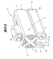
- Fig. 2
- den Seitenkanalverdichter in einer Perspektivdarstellung;
- Fig. 3
- in perspektivischer Darstellung den Seitenkanalverdichter mit angeflanschtem Elektromotor und Kühlluftgebläse so- wie einer Steuerelektronik unter Fortlassung der stirnseiti- gen Abdeckung und einer Luftführungs-Halbschale;
- Fig. 4
- in perspektivischer Darstellung ein, einen Ansaugkanal und einen Ausblaskanal zusammenfassendes Gehäuse mit einem auswechselbaren Umschalteinsatz;
- Fig. 5
- in perspektivischer Rückansicht das geschnittene Gehäuse mit einem gesondert dargestellten, gegenüber dem Um- schalteinsatz gemäß
Fig. 4 geänderten Umschalteinsatz; - Fig. 6
- eine der
Fig. 4 entsprechende Darstellung, jedoch bei Bestü- ckung mit dem Umschalteinsatz gemäßFig. 5 ; - Fig. 7
- den Seitenkanalverdichter in Perspektive, eine zweite Aus- führungsform betreffend.
- Dargestellt und beschrieben ist ein Seitenkanalverdichter 1, welcher in der dargestellten Ausführungsform als zweiflutiger Verdichter ausgebildet ist. Entsprechend sind zwei Seitenkanäle vorgesehen, die mit einem nicht dargestellten doppelseitig beschaufelten Laufrad zusammenwirken. Das Laufrad der Seitenkanäle wird angetrieben über einen Elektromotor 2. Dieser ist an dem Seitenkanalverdichter angeflanscht. Die Motordrehwelle ist drehfest mit dem Gebläserad verbunden, wobei Gebläseachse und Motorachse eine gemeinsame Achse x bilden. Der Motor ist außenseitig mit axial ausgerichteten Kühlrippen 3 versehen. Diese erstrecken sich über die gesamte Länge des Motors bis hin zu den Seitenkanälen, dies bei gleichbleibender axialer Kontur zur störungsfreien Umströmung Auf der dem Seitenkanalverdichter 1 abgewandten Seite des Elektromotors 2 ist ein Kühlluftgebläse 4 an dem Elektromotor 2 angeflanscht. Deren Lüfterrad 5 steht drehfest mit der Motorwelle in Verbindung, demzufolge das Kühlluftgebläse 4 direkt über den Elektromotor 2 angetrieben wird.
- Auf dem Elektromotor 2 bzw. dem Motorgehäuse ist ein Elektroanschlussgehäuse 6 montiert. Dieses beinhaltet zugleich die Elektronik zur Steuerung des Elektromotors 2 bzw. des Seitenkanalverdichters 1.
- Die mit den Kühlrippen 3 versehene Außenwandung des Elektromotors 2 sowie das Kühlluftgebläse 4 sind überdeckt von Luftführungsschalen 7. Diese sind gebildet als Kunststoffprofile, die an den Kühlrippen 3 angeklipst sind. Hierdurch sind die Luftführungsschalen 7 zum Motor 2 entkoppelt und bieten eine entsprechende Schalldämpfung der gesamten Vorrichtung.
- Die Luftführungsschalen 7 erstrecken sich von dem Seitenkanalverdichter ausgehend über die gesamte Länge des Elektromotors 2, das Kühlluftgebläse 4 umfassend. Hierdurch ist eine Luftströmungsführung entlang des Elektromotors 2 erreicht, so dass der durch das Kühlluftgebläse 4 aufgebaute Kühlluftstrom entlang dem Motorgehäuse geführt wird. Zugleich wird auch der Verdichter über diesen Luftstrom gekühlt. Motor 2, Verdichter und Elektronik sind wärmeleitend in Längsrichtung verbunden, was weiter zu einem Temperaturausgleich beiträgt.
- Stirnseitig, d. h. zugeordnet dem Kühlluftgebläse 4 ist der durch die Luftführungsschalen 7 definierte Kühlluft-Strömungskanal von einer gitterartigen und entsprechend luftdurchlässigen Stirnwand 8 überdeckt.
- Unterflurseitig des Elektromotors 2 erstreckt sich ein im Querschnitt annähernd rechteckiges Gehäuse 9. Dieses besteht in dem dargestellten Ausführungsbeispiel aus einem Aluminium-Strangpressprofil. Dieses Gehäuse 9 erstreckt sich über die gesamte Länge der durch das Kühlluftgebläse 4, den Elektromotor 2 und den Seitenkanalverdichter 1 gebildeten Einheit. Die quer hierzu betrachtete Breite entspricht in dem dargestellten Ausführungsbeispiel der quer zur Achse x gemessenen Breite der auf dem Gehäuse 9 aufsitzenden Einheit inklusive der aufgesetzten Luftführungsschalen 7 (vgl.
Fig.1 ). - Das Gehäuse 9 dient entsprechend als Sockel 10 für den Elektromotor 2 und dem Seitenkanalverdichter 1.
- Das Gehäuse 9 formt im Querschnitt gemäß der Darstellung in
Fig. 1 zwei gesonderte Kanäle 11 und 12. Diese sind gebildet durch eine mittige, senkrecht ausgerichtete Trennwand 13, die materialeinheitlich, einstückig mit der Gehäusewandung geformt ist. Durch die mittige Trennwand 13 sind zwei im Querschnitt gleich große Kanäle 11 und 12 geschaffen, welche Kanäle 11 und 12 ausgerichtet entlang der Achse x über die gesamte Länge des Gehäuses 9 verlaufen. Möglich ist auch eine außenmittige Anordnung zur Bildung unterschiedlich große Kanalquerschnitte. - Endseitig, zugeordnet dem Seitenkanalverdichter 1 ist das Gehäuse 9 verschlossen, dies weiter unter strikter Trennung der Kanäle 11 und 12.
- Die Kanäle 11 und 12 nehmen einen Ansaugkanal 14 und einen Ausblaskanal 15 zum Betrieb des Seitenkanalverdichters 1 auf. Ansaugkanal 14 und Ausblaskanal 15 sind rohrartiger Gestalt und erstrecken sich nahezu über die gesamte Länge des Gehäuses 9.
- Die dem Seitenkanalverdichter 1 abgewandte Stirnseite des Gehäuses 9 ist mit einer, Anschlussdurchbrechungen 16 aufweisenden Abdeckung 17 verschlossen.
- Zumindest der Ausblaskanal 15 ist von einer wärmedämmenden Isolierung 18 umfasst. Auch der Ansaugkanal 14 kann über eine solche Isolierung verfügen. Die dem Elektromotor 2 zugewandte Gehäusedecke 19 ist querschnittsmäßig so gestaltet, dass sich zwischen Elektromotor 2 und Gehäuse 9 ein sich in Axialrichtung erstreckender Luftführungsschlitz 20 einstellt. Durch diesen wird im Betrieb über das Kühlluftgebläse 4 weitere Kühlluft gesogen.
- Die in dem als Schalldämpfer wirkenden Gehäuse 9 aufgenommenen Ansaug- und Ausblaskanäle stehen strömungstechnisch mit den Lufteintritts- und Luftaustrittskanälen der Seitenkanäle in Verbindung. Hierzu ist in der Gehäusedecke 19, zugeordnet dem Seitenkanalverdichter 1 ein Anschlussbereich 21 geschaffen, in welchem eine Umlenkung der anströmenden bzw. abströmenden Luft um 90° aus einer senkrecht zur Achse x ausgerichteten Strömung in eine in Achsrichtung gerichtete Strömung erfolgt.
- Ist, wie in dem dargestellten Ausführungsbeispiel vorgesehen, der Seitenkanalverdichter 1 zweiflutig gestaltet, d. h. mit zwei Seitenkanälen versehen, so sind entsprechend auch zwei Lufteintrittskanäle und zwei Luftaustrittskanäle, die jeweils in Verbindung zu den Ansaug- und Ausblaskanälen stehen, ausgeformt. Durch Einsetzen eines Umschalteinsatzes 22 in dem Anschlussbereich 21 ist die wahlweise Konfiguration des Seitenkanalverdichters 1 entweder als zweiflutiger Verdichter oder als zweistufiger Verdichter und darüber hinaus auch durch entsprechende Absperrungen als einflutige Verdichter möglich.
- Für jede Konfiguration ist ein Umschalteinsatz 22 bzw. 22' vorgesehen. In
Fig. 4 ist ein Umschalteinsatz 22 dargestellt zum zweiflutigen Betrieb des Seitenkanalverdichters 1. Dieser Umschalteinsatz 22 ist als Kunststoffteil im Spritzgussverfahren gefertigt und weist eine im Grundriss quadratische Deckplatte 23 auf. Diese ist anschlagbegrenzt einsetzbar in eine angepasste, die Kanäle 11 und 12 des Gehäuses 9 im Bereich der Gehäusedecke 19 übergreifende Aussparung 24 im Anschlussbereich 21. Unterseitig der Deckplatte 23 erstreckt sich senkrecht nach unten eine Verschlusswand 25. Diese greift in einen entsprechend angepassten Ausschnitt 26 der Gehäusetrennwand 13 ein, zum dichtenden Verschluss dieses Ausschnittes 26 und somit zur Sicherstellung der strömungstechnischen Trennung von Ansaugkanal 14 und Ausblaskanal 15. - In der Deckplatte 23 sind jeweils zugeordnet den nicht dargestellten Lufteintritts- und Luftaustrittskanälen der Seitenkanäle Eintrittsöffnungen 27 und Austrittsöffnungen 28 ausgeformt, wobei die Eintrittsöffnungen 27 dem Ansaugkanal 14 und die Austrittsöffnungen 28 dem Ausblaskanal 15 zugeordnet sind.
- Mittels dieses Umschalteinsatzes 22 werden beide Seitenkanäle unabhängig voneinander betrieben, dies unter Anströmen über einen gemeinsamen Ansaugkanal 14 und Abströmen über einen gemeinsamen Ausblaskanal 15.
- Zum zweistufigen Betrieb des Seitenkanalverdichters 1 ist der Luftaustrittskanal des ersten Seitenkanals mit dem Lufteintrittskanal des zweiten Seitenkanals kurzzuschließen. Hierzu kommt der in den
Fig. 5 und6 dargestellte Umschalteinsatz 22' zum Einsatz. Auch dieser verfügt zunächst über eine Deckplatte 23 und eine senkrecht hierzu nach unten gerichtete Verschlusswand 25. In der Deckplatte 23 ist eine Eintrittsöffnung 27 für einen ersten Seitenkanal und eine Austrittsöffnung 28 für den zweiten Seitenkanal vorgesehen, welche Öffnungen direkt mit dem Ansaugkanal 14 bzw. dem Ausblaskanal 15 in Verbindung stehen. - Die Austrittsöffnung 28 des ersten Seitenkanals und die Eintrittsöffnung 27 des zweiten Seitenkanals sind bei diesem Umschalteinsatz 22' über einen in dem Umschalteinsatz 22' ausgeformten Verbindungskanal 29 kurzgeschlossen. Dieser ist wannenartig unterseitig der Deckplatte 23, die Verschlusswand 25 durchsetzend ausgeformt.
- Bei Seitenkanalverdichtern, die mehr als zwei Seitenkanäle, so weiter beispielsweise vier Seitenkanäle, aufweisen, liegt entsprechend eine größere Auswahl unterschiedlich Umschalteinsätze 22 bzw. 22' vor, so weiter beispielsweise zum vierflutigen, einstufigen Betrieb oder zum zweiflutigen, zweistufigen oder darüber hinaus zum einflutigen vierstufigen Betrieb des Seitenkanalverdichters 1.
- Der Umschalteinsatz 22 bzw. 22' liegt dichtend in der Aussparung 24 und weiter abdichtend in dem Ausschnitt 26 ein, wobei die Abdichtung beispielsweise durch plastisch verformbare Kanten an dem als Kunststoffteil gebildeten Umschalteinsatz 22 bzw. 22' erreicht sein kann. Darüber hinaus auch durch Kleben oder durch Anordnung einer Dichtwulst oder dgl.
- Das Gehäuse 9 und die darüber angeordnete Einheit aus Elektromotor 2 und Seitenkanalverdichter 1 sind des Weiteren wärmeleitend verbunden, so dass der durch den Ansaugkanal 14 geführte kalte Saugluftstrom zur Gehäusekühlung genutzt werden kann. Die dem gegenüber heiße Abluft im Ausblaskanal 15 ist thermisch durch die Isolierung 18 entkoppelt.
-
Fig. 7 zeigt eine zweite Ausführungsform des Seitenkanalverdichters 1, in welcher das Gehäuse 9 nicht unterflurseitig angeordnet ist, sondern vielmehr unter Zwischenschaltung eines Adapters 30 auf dem Seitenkanalverdichter aufsitzt, dies unter Einschluss eines rechten Winkels zur Achse x.
Claims (6)
- Seitenkanalverdichter (1) mit zwei Seitenkanälen, mit einem Ansaugkanal (14) und einem Ausblaskanal (15), wobei der Ansaugkanal (14) und der Ausblaskanal (15) in einem gemeinsamen Gehäuse (9) zusammengefasst sind, mit einer gemeinsamen, die Kanäle (11,12) sondernden Trennwand (13), die Ansaug- und Ausblaskanäle (14,15) parallel geführt sind und ein auswechselbarer Umschalteinsatz (22, 22') vorgesehen ist, wobei weiter jedenfalls der Ausblaskanal (15) eine Isolierung (18) aufweist, der Umschalteinsatz (22, 22') einem Anschlussbereich (21) an den Seitenkanalverdichter (1) zugeordnet ist und der Umschalteinsatz eine Deckplatte (23) mit einer in der Deckplatte (23) vorgesehenen Eintrittsöffnung (27) für einen ersten Seitenkanal und einer in der Deckplatte vorgeschenen Austrittsöffnung (28) für den zweiten Seitenkanal aufweist, dadurch gekennzeichnet, dass die Deckplatte (23) eine senkrecht hierzu gerichtete Verschlusswand (25) aufweist.
- Seitenkanalverdichter (1) nach Anspruch 1, dadurch gekennzeichnet, dass das Gehäuse (9) als Sockel (10) für den Seitenkanalverdichter (1) einschließlich des zugehörigen Motors (2) und der Steuerelektronik dient.
- Seitenkanalverdichter (1) nach Anspruch 1 oder 2, dadurch gekennzeichnet, dass in der Gehäusedecke (19) des endseitig, zugeordnet dem Seitenkanalverdichter, geschlossenen und sich über die gesamte Länge der durch ein Kühlluftgebläse (4), den Elektromotor (2) und den Seitenkanalverdichter (1) gebildeten Einheit erstreckenden Gehäuses (9), zugeordnet dem Seitenkanalverdichter (1), ein Anschlussbereich (21) geschaffen ist, in welchem eine Umlenkung der anströmenden bzw. abströmenden Luft um 90° aus einer senkrecht zur Achse (x) der Kanäle (11,12) ausgerichteten Strömung in eine in Achsrichtung gerichtete Strömung erfolgt.
- Seitenkanalverdichter nach einem der Ansprüche 1 bis 3, dadurch gekennzeichnet, dass die Kanäle (14, 15) einerseits, der Seitenkanalverdichter (1) mit angeflanschtem Motor (2) andererseits und darüber hinaus die Steuerelektronik etagenartig übereinander angeordnet sind.
- Seitenkanalverdichter nach einem der Ansprüche 1 bis 1, dadurch gekennzeichnet, dass das die Kanäle (14, 15) zusammenfassende Gehäuse (9) aus einem Metallwerkstoff besteht und der Umschalteinsatz (22,22') aus einem Kunststoffwerkstoff.
- Seitenkanalverdichter nach einem der Ansprüche 1 bis 5, dadurch gekennzeichnet, dass axial an dem Elektromotor (2) angeflanscht ein Kühlluftgebläse (4) vorgesehen ist.
Priority Applications (1)
| Application Number | Priority Date | Filing Date | Title |
|---|---|---|---|
| EP10150253.2A EP2166232B1 (de) | 2007-04-13 | 2008-04-11 | Seitenkanalverdichter |
Applications Claiming Priority (2)
| Application Number | Priority Date | Filing Date | Title |
|---|---|---|---|
| DE102007017915A DE102007017915A1 (de) | 2007-04-13 | 2007-04-13 | Seitenkanalverdichter |
| PCT/EP2008/054427 WO2008125630A1 (de) | 2007-04-13 | 2008-04-11 | Seitenkanalverdichter |
Related Child Applications (2)
| Application Number | Title | Priority Date | Filing Date |
|---|---|---|---|
| EP10150253.2A Division EP2166232B1 (de) | 2007-04-13 | 2008-04-11 | Seitenkanalverdichter |
| EP10150253.2 Division-Into | 2010-01-07 |
Publications (2)
| Publication Number | Publication Date |
|---|---|
| EP2142805A1 EP2142805A1 (de) | 2010-01-13 |
| EP2142805B1 true EP2142805B1 (de) | 2011-08-24 |
Family
ID=39539517
Family Applications (2)
| Application Number | Title | Priority Date | Filing Date |
|---|---|---|---|
| EP10150253.2A Active EP2166232B1 (de) | 2007-04-13 | 2008-04-11 | Seitenkanalverdichter |
| EP08736138A Active EP2142805B1 (de) | 2007-04-13 | 2008-04-11 | Seitenkanalverdichter |
Family Applications Before (1)
| Application Number | Title | Priority Date | Filing Date |
|---|---|---|---|
| EP10150253.2A Active EP2166232B1 (de) | 2007-04-13 | 2008-04-11 | Seitenkanalverdichter |
Country Status (4)
| Country | Link |
|---|---|
| EP (2) | EP2166232B1 (de) |
| AT (1) | ATE521809T1 (de) |
| DE (1) | DE102007017915A1 (de) |
| WO (1) | WO2008125630A1 (de) |
Families Citing this family (6)
| Publication number | Priority date | Publication date | Assignee | Title |
|---|---|---|---|---|
| DE102010041139B4 (de) * | 2010-09-21 | 2018-03-29 | Eberspächer Climate Control Systems GmbH & Co. KG | Seitenkanalgebläse für ein Fahrzeugheizgerät |
| DE102011004512A1 (de) | 2011-02-22 | 2012-08-23 | Gardner Denver Deutschland Gmbh | Seitenkanal-Maschinen-Anordnung |
| DE102012101185B4 (de) | 2011-08-03 | 2025-07-10 | Gebr. Becker Gmbh | Filterteil |
| DE102015107721A1 (de) | 2015-05-18 | 2016-11-24 | Gebr. Becker Gmbh | Ölgeschmierte Drehschieber-Vakuumpumpe |
| BE1023523B1 (nl) | 2015-09-25 | 2017-04-19 | Atlas Copco Airpower, N.V. | Werkwijze voor het koelen van een compressor of vacuümpomp en een compressor of vacuümpomp die een dergelijke werkwijze toepast |
| WO2017049368A2 (en) * | 2015-09-25 | 2017-03-30 | Atlas Copco Airpower,Naamloze Vennootschap | Method for cooling a compressor or vacuum pump and a compressor or vacuum pump applying such a method |
Family Cites Families (8)
| Publication number | Priority date | Publication date | Assignee | Title |
|---|---|---|---|---|
| FR2043926A5 (de) * | 1969-05-02 | 1971-02-19 | Manoury Leon | |
| DE2223762A1 (de) * | 1972-05-16 | 1973-11-29 | Elektror Karl W Mueller | Druck- und volumenregler fuer motorisch angetriebene verdichter fuer gase oder foerdereinrichtungen von fluessigkeiten |
| DE2433094C3 (de) * | 1974-07-10 | 1981-05-27 | Elektror Karl W. Müller GmbH & Co, 7300 Esslingen | Seitenkanalverdichter |
| US5049770A (en) * | 1990-03-26 | 1991-09-17 | General Motors Corporation | Electric motor-driven impeller-type air pump |
| DE69119854T2 (de) * | 1990-09-14 | 1996-10-10 | Hitachi Ltd | Seitenkanalgebläse |
| KR970005981B1 (ko) | 1991-06-18 | 1997-04-22 | 가부시기가이샤 히다찌세이사뀨쇼 | 와류블로워 |
| AU7489496A (en) * | 1995-09-15 | 1997-04-01 | Siemens Aktiengesellschaft | Housing for a sound absorber which can be connected to a compressor |
| US7033137B2 (en) * | 2004-03-19 | 2006-04-25 | Ametek, Inc. | Vortex blower having helmholtz resonators and a baffle assembly |
-
2007
- 2007-04-13 DE DE102007017915A patent/DE102007017915A1/de not_active Withdrawn
-
2008
- 2008-04-11 EP EP10150253.2A patent/EP2166232B1/de active Active
- 2008-04-11 AT AT08736138T patent/ATE521809T1/de active
- 2008-04-11 WO PCT/EP2008/054427 patent/WO2008125630A1/de not_active Ceased
- 2008-04-11 EP EP08736138A patent/EP2142805B1/de active Active
Also Published As
| Publication number | Publication date |
|---|---|
| DE102007017915A1 (de) | 2008-10-23 |
| EP2166232B1 (de) | 2015-08-12 |
| EP2142805A1 (de) | 2010-01-13 |
| WO2008125630A1 (de) | 2008-10-23 |
| EP2166232A1 (de) | 2010-03-24 |
| ATE521809T1 (de) | 2011-09-15 |
Similar Documents
| Publication | Publication Date | Title |
|---|---|---|
| EP2142805B1 (de) | Seitenkanalverdichter | |
| DE112015002457B4 (de) | Klimaanlage für ein Fahrzeug und Verfahren zum Steuern dafür | |
| DE69620669T2 (de) | Lärmdämpfungsgerät eines Lüfters | |
| DE102008025386A1 (de) | Klimaanlage für Fahrzeuge | |
| EP1703618B1 (de) | Luftgekühlter Elektromotor | |
| DE102013106209A1 (de) | Wärmeübertrageranordnung zur Wärmeaufnahme und Klimatisierungssystem eines Kraftfahrzeuges | |
| DE112013001895T5 (de) | Öffnungs-/Schließvorrichtung für einen Luftdurchlass | |
| EP2000337B1 (de) | Gebläseanordnung zur Belüftung eines Fahrzeugs | |
| DE19745535B4 (de) | Klimaanlage für ein Fahrzeug | |
| EP3194774A1 (de) | MEHRSTUFIGER KOLBENKOMPRESSOR MIT EINER ÄUßEREN KÜHLLUFTFÜHRUNG | |
| EP1995463A2 (de) | Mehrstufige Verdichtereinheit mit Kühleinrichtung | |
| DE112015003764T5 (de) | Klimaanlage für ein Fahrzeug | |
| DE102007001877A1 (de) | Klimaanlage | |
| EP4232758B1 (de) | Lüftungsvorrichtung | |
| DE102009040545A1 (de) | Zentrifugalgebläse | |
| DE602006000387T2 (de) | Doppelgebläseanordnung für Kraftfahrzeuge | |
| DE112017000930B4 (de) | Luftkonditioniereinheit für ein fahrzeug | |
| DE102005016820B4 (de) | Großmotor | |
| EP2080970B1 (de) | Kühl- und/oder Gefriergerät | |
| EP1384606B1 (de) | Gebläseanordnung und Verfahren zur Belüftung eines Fahrzeugs | |
| DE102004010632A1 (de) | Kraftfahrzeug mit doppeltem Kühler | |
| DE10234345A1 (de) | Gebläseanordnung und Verfahren zur Belüftung eines Fahrzeuges | |
| EP2080910B1 (de) | Gebläse, insbesondere Fahrzeuggebläse | |
| DE10330541A1 (de) | Drehschieber-Vakuumpumpe bzw. -Verdichter | |
| DE102008010182A1 (de) | Gehäuse für eine Gasfördereinrichtung |
Legal Events
| Date | Code | Title | Description |
|---|---|---|---|
| PUAI | Public reference made under article 153(3) epc to a published international application that has entered the european phase |
Free format text: ORIGINAL CODE: 0009012 |
|
| 17P | Request for examination filed |
Effective date: 20091030 |
|
| AK | Designated contracting states |
Kind code of ref document: A1 Designated state(s): AT BE BG CH CY CZ DE DK EE ES FI FR GB GR HR HU IE IS IT LI LT LU LV MC MT NL NO PL PT RO SE SI SK TR |
|
| 17Q | First examination report despatched |
Effective date: 20100204 |
|
| DAX | Request for extension of the european patent (deleted) | ||
| GRAP | Despatch of communication of intention to grant a patent |
Free format text: ORIGINAL CODE: EPIDOSNIGR1 |
|
| GRAS | Grant fee paid |
Free format text: ORIGINAL CODE: EPIDOSNIGR3 |
|
| GRAA | (expected) grant |
Free format text: ORIGINAL CODE: 0009210 |
|
| AK | Designated contracting states |
Kind code of ref document: B1 Designated state(s): AT BE BG CH CY CZ DE DK EE ES FI FR GB GR HR HU IE IS IT LI LT LU LV MC MT NL NO PL PT RO SE SI SK TR |
|
| REG | Reference to a national code |
Ref country code: GB Ref legal event code: FG4D Free format text: NOT ENGLISH |
|
| REG | Reference to a national code |
Ref country code: CH Ref legal event code: EP |
|
| REG | Reference to a national code |
Ref country code: IE Ref legal event code: FG4D Free format text: LANGUAGE OF EP DOCUMENT: GERMAN |
|
| REG | Reference to a national code |
Ref country code: DE Ref legal event code: R096 Ref document number: 502008004600 Country of ref document: DE Effective date: 20111020 |
|
| REG | Reference to a national code |
Ref country code: NL Ref legal event code: T3 |
|
| LTIE | Lt: invalidation of european patent or patent extension |
Effective date: 20110824 |
|
| PG25 | Lapsed in a contracting state [announced via postgrant information from national office to epo] |
Ref country code: NO Free format text: LAPSE BECAUSE OF FAILURE TO SUBMIT A TRANSLATION OF THE DESCRIPTION OR TO PAY THE FEE WITHIN THE PRESCRIBED TIME-LIMIT Effective date: 20111124 Ref country code: LT Free format text: LAPSE BECAUSE OF FAILURE TO SUBMIT A TRANSLATION OF THE DESCRIPTION OR TO PAY THE FEE WITHIN THE PRESCRIBED TIME-LIMIT Effective date: 20110824 Ref country code: FI Free format text: LAPSE BECAUSE OF FAILURE TO SUBMIT A TRANSLATION OF THE DESCRIPTION OR TO PAY THE FEE WITHIN THE PRESCRIBED TIME-LIMIT Effective date: 20110824 Ref country code: SE Free format text: LAPSE BECAUSE OF FAILURE TO SUBMIT A TRANSLATION OF THE DESCRIPTION OR TO PAY THE FEE WITHIN THE PRESCRIBED TIME-LIMIT Effective date: 20110824 Ref country code: HR Free format text: LAPSE BECAUSE OF FAILURE TO SUBMIT A TRANSLATION OF THE DESCRIPTION OR TO PAY THE FEE WITHIN THE PRESCRIBED TIME-LIMIT Effective date: 20110824 Ref country code: PT Free format text: LAPSE BECAUSE OF FAILURE TO SUBMIT A TRANSLATION OF THE DESCRIPTION OR TO PAY THE FEE WITHIN THE PRESCRIBED TIME-LIMIT Effective date: 20111226 Ref country code: IS Free format text: LAPSE BECAUSE OF FAILURE TO SUBMIT A TRANSLATION OF THE DESCRIPTION OR TO PAY THE FEE WITHIN THE PRESCRIBED TIME-LIMIT Effective date: 20111224 |
|
| PG25 | Lapsed in a contracting state [announced via postgrant information from national office to epo] |
Ref country code: SI Free format text: LAPSE BECAUSE OF FAILURE TO SUBMIT A TRANSLATION OF THE DESCRIPTION OR TO PAY THE FEE WITHIN THE PRESCRIBED TIME-LIMIT Effective date: 20110824 Ref country code: LV Free format text: LAPSE BECAUSE OF FAILURE TO SUBMIT A TRANSLATION OF THE DESCRIPTION OR TO PAY THE FEE WITHIN THE PRESCRIBED TIME-LIMIT Effective date: 20110824 Ref country code: GR Free format text: LAPSE BECAUSE OF FAILURE TO SUBMIT A TRANSLATION OF THE DESCRIPTION OR TO PAY THE FEE WITHIN THE PRESCRIBED TIME-LIMIT Effective date: 20111125 Ref country code: PL Free format text: LAPSE BECAUSE OF FAILURE TO SUBMIT A TRANSLATION OF THE DESCRIPTION OR TO PAY THE FEE WITHIN THE PRESCRIBED TIME-LIMIT Effective date: 20110824 Ref country code: CY Free format text: LAPSE BECAUSE OF FAILURE TO SUBMIT A TRANSLATION OF THE DESCRIPTION OR TO PAY THE FEE WITHIN THE PRESCRIBED TIME-LIMIT Effective date: 20110824 |
|
| REG | Reference to a national code |
Ref country code: IE Ref legal event code: FD4D |
|
| PG25 | Lapsed in a contracting state [announced via postgrant information from national office to epo] |
Ref country code: SK Free format text: LAPSE BECAUSE OF FAILURE TO SUBMIT A TRANSLATION OF THE DESCRIPTION OR TO PAY THE FEE WITHIN THE PRESCRIBED TIME-LIMIT Effective date: 20110824 Ref country code: CZ Free format text: LAPSE BECAUSE OF FAILURE TO SUBMIT A TRANSLATION OF THE DESCRIPTION OR TO PAY THE FEE WITHIN THE PRESCRIBED TIME-LIMIT Effective date: 20110824 Ref country code: IE Free format text: LAPSE BECAUSE OF FAILURE TO SUBMIT A TRANSLATION OF THE DESCRIPTION OR TO PAY THE FEE WITHIN THE PRESCRIBED TIME-LIMIT Effective date: 20110824 |
|
| PG25 | Lapsed in a contracting state [announced via postgrant information from national office to epo] |
Ref country code: EE Free format text: LAPSE BECAUSE OF FAILURE TO SUBMIT A TRANSLATION OF THE DESCRIPTION OR TO PAY THE FEE WITHIN THE PRESCRIBED TIME-LIMIT Effective date: 20110824 Ref country code: RO Free format text: LAPSE BECAUSE OF FAILURE TO SUBMIT A TRANSLATION OF THE DESCRIPTION OR TO PAY THE FEE WITHIN THE PRESCRIBED TIME-LIMIT Effective date: 20110824 |
|
| PG25 | Lapsed in a contracting state [announced via postgrant information from national office to epo] |
Ref country code: DK Free format text: LAPSE BECAUSE OF FAILURE TO SUBMIT A TRANSLATION OF THE DESCRIPTION OR TO PAY THE FEE WITHIN THE PRESCRIBED TIME-LIMIT Effective date: 20110824 |
|
| PLBE | No opposition filed within time limit |
Free format text: ORIGINAL CODE: 0009261 |
|
| STAA | Information on the status of an ep patent application or granted ep patent |
Free format text: STATUS: NO OPPOSITION FILED WITHIN TIME LIMIT |
|
| 26N | No opposition filed |
Effective date: 20120525 |
|
| REG | Reference to a national code |
Ref country code: DE Ref legal event code: R097 Ref document number: 502008004600 Country of ref document: DE Effective date: 20120525 |
|
| BERE | Be: lapsed |
Owner name: GEBR. BECKER G.M.B.H. Effective date: 20120430 |
|
| PG25 | Lapsed in a contracting state [announced via postgrant information from national office to epo] |
Ref country code: MC Free format text: LAPSE BECAUSE OF NON-PAYMENT OF DUE FEES Effective date: 20120430 |
|
| REG | Reference to a national code |
Ref country code: CH Ref legal event code: PL |
|
| PG25 | Lapsed in a contracting state [announced via postgrant information from national office to epo] |
Ref country code: LI Free format text: LAPSE BECAUSE OF NON-PAYMENT OF DUE FEES Effective date: 20120430 Ref country code: CH Free format text: LAPSE BECAUSE OF NON-PAYMENT OF DUE FEES Effective date: 20120430 Ref country code: BE Free format text: LAPSE BECAUSE OF NON-PAYMENT OF DUE FEES Effective date: 20120430 |
|
| PG25 | Lapsed in a contracting state [announced via postgrant information from national office to epo] |
Ref country code: ES Free format text: LAPSE BECAUSE OF FAILURE TO SUBMIT A TRANSLATION OF THE DESCRIPTION OR TO PAY THE FEE WITHIN THE PRESCRIBED TIME-LIMIT Effective date: 20111205 |
|
| PG25 | Lapsed in a contracting state [announced via postgrant information from national office to epo] |
Ref country code: BG Free format text: LAPSE BECAUSE OF FAILURE TO SUBMIT A TRANSLATION OF THE DESCRIPTION OR TO PAY THE FEE WITHIN THE PRESCRIBED TIME-LIMIT Effective date: 20111124 |
|
| PG25 | Lapsed in a contracting state [announced via postgrant information from national office to epo] |
Ref country code: MT Free format text: LAPSE BECAUSE OF FAILURE TO SUBMIT A TRANSLATION OF THE DESCRIPTION OR TO PAY THE FEE WITHIN THE PRESCRIBED TIME-LIMIT Effective date: 20110824 |
|
| PG25 | Lapsed in a contracting state [announced via postgrant information from national office to epo] |
Ref country code: TR Free format text: LAPSE BECAUSE OF FAILURE TO SUBMIT A TRANSLATION OF THE DESCRIPTION OR TO PAY THE FEE WITHIN THE PRESCRIBED TIME-LIMIT Effective date: 20110824 |
|
| PG25 | Lapsed in a contracting state [announced via postgrant information from national office to epo] |
Ref country code: LU Free format text: LAPSE BECAUSE OF NON-PAYMENT OF DUE FEES Effective date: 20120411 |
|
| REG | Reference to a national code |
Ref country code: AT Ref legal event code: MM01 Ref document number: 521809 Country of ref document: AT Kind code of ref document: T Effective date: 20130411 |
|
| PG25 | Lapsed in a contracting state [announced via postgrant information from national office to epo] |
Ref country code: HU Free format text: LAPSE BECAUSE OF FAILURE TO SUBMIT A TRANSLATION OF THE DESCRIPTION OR TO PAY THE FEE WITHIN THE PRESCRIBED TIME-LIMIT Effective date: 20080411 |
|
| PG25 | Lapsed in a contracting state [announced via postgrant information from national office to epo] |
Ref country code: AT Free format text: LAPSE BECAUSE OF NON-PAYMENT OF DUE FEES Effective date: 20130411 |
|
| REG | Reference to a national code |
Ref country code: FR Ref legal event code: PLFP Year of fee payment: 9 |
|
| REG | Reference to a national code |
Ref country code: FR Ref legal event code: PLFP Year of fee payment: 10 |
|
| REG | Reference to a national code |
Ref country code: FR Ref legal event code: PLFP Year of fee payment: 11 |
|
| PGFP | Annual fee paid to national office [announced via postgrant information from national office to epo] |
Ref country code: FR Payment date: 20190410 Year of fee payment: 12 |
|
| PGFP | Annual fee paid to national office [announced via postgrant information from national office to epo] |
Ref country code: GB Payment date: 20190410 Year of fee payment: 12 |
|
| REG | Reference to a national code |
Ref country code: NL Ref legal event code: MM Effective date: 20190501 |
|
| PG25 | Lapsed in a contracting state [announced via postgrant information from national office to epo] |
Ref country code: NL Free format text: LAPSE BECAUSE OF NON-PAYMENT OF DUE FEES Effective date: 20190501 |
|
| PG25 | Lapsed in a contracting state [announced via postgrant information from national office to epo] |
Ref country code: FR Free format text: LAPSE BECAUSE OF NON-PAYMENT OF DUE FEES Effective date: 20200430 |
|
| GBPC | Gb: european patent ceased through non-payment of renewal fee |
Effective date: 20200411 |
|
| PG25 | Lapsed in a contracting state [announced via postgrant information from national office to epo] |
Ref country code: GB Free format text: LAPSE BECAUSE OF NON-PAYMENT OF DUE FEES Effective date: 20200411 |
|
| P01 | Opt-out of the competence of the unified patent court (upc) registered |
Effective date: 20230523 |
|
| PGFP | Annual fee paid to national office [announced via postgrant information from national office to epo] |
Ref country code: DE Payment date: 20250416 Year of fee payment: 18 |
|
| PGFP | Annual fee paid to national office [announced via postgrant information from national office to epo] |
Ref country code: IT Payment date: 20250417 Year of fee payment: 18 |