EP2143184B1 - Procédé de déclenchement sélectif d'interrupteurs de puissance - Google Patents
Procédé de déclenchement sélectif d'interrupteurs de puissance Download PDFInfo
- Publication number
- EP2143184B1 EP2143184B1 EP08736632.4A EP08736632A EP2143184B1 EP 2143184 B1 EP2143184 B1 EP 2143184B1 EP 08736632 A EP08736632 A EP 08736632A EP 2143184 B1 EP2143184 B1 EP 2143184B1
- Authority
- EP
- European Patent Office
- Prior art keywords
- circuit
- breaker
- upstream
- short
- downstream
- Prior art date
- Legal status (The legal status is an assumption and is not a legal conclusion. Google has not performed a legal analysis and makes no representation as to the accuracy of the status listed.)
- Not-in-force
Links
- 238000000034 method Methods 0.000 title claims description 14
- 238000011144 upstream manufacturing Methods 0.000 claims description 24
- 230000001419 dependent effect Effects 0.000 claims description 6
- 230000004913 activation Effects 0.000 claims description 4
- 230000015572 biosynthetic process Effects 0.000 claims 1
- 240000006829 Ficus sundaica Species 0.000 description 1
- 206010000210 abortion Diseases 0.000 description 1
- 230000006978 adaptation Effects 0.000 description 1
- 230000002950 deficient Effects 0.000 description 1
- 238000001514 detection method Methods 0.000 description 1
- 238000012544 monitoring process Methods 0.000 description 1
Images

Classifications
-
- H—ELECTRICITY
- H02—GENERATION; CONVERSION OR DISTRIBUTION OF ELECTRIC POWER
- H02H—EMERGENCY PROTECTIVE CIRCUIT ARRANGEMENTS
- H02H7/00—Emergency protective circuit arrangements specially adapted for specific types of electric machines or apparatus or for sectionalised protection of cable or line systems, and effecting automatic switching in the event of an undesired change from normal working conditions
- H02H7/26—Sectionalised protection of cable or line systems, e.g. for disconnecting a section on which a short-circuit, earth fault, or arc discharge has occured
- H02H7/30—Staggered disconnection
-
- H—ELECTRICITY
- H02—GENERATION; CONVERSION OR DISTRIBUTION OF ELECTRIC POWER
- H02H—EMERGENCY PROTECTIVE CIRCUIT ARRANGEMENTS
- H02H1/00—Details of emergency protective circuit arrangements
- H02H1/0007—Details of emergency protective circuit arrangements concerning the detecting means
- H02H1/0015—Using arc detectors
Definitions
- the invention relates to a method for the selective release of an upstream and at least one subordinate circuit breaker according to the preamble of claim 1.
- circuit breakers in the event of a short circuit. This means that in each case the circuit breaker triggers, which is closest to the short circuit seen from the power supply, so that no more consumers are unavoidably affected by the shutdown.
- the mutually before and downstream circuit breakers are subject to a current and time graduation; In each case, the circuit breakers close to the supply point have longer switch-off times than the downstream ones. This ensures that the upstream circuit breakers only switch off when they are closest to the short circuit or in emergencies where a downstream circuit breaker does not trip although it should trip.
- the current-time characteristics of the circuit breakers are coordinated so that they trigger in the event of a short circuit in the feed direction at ever higher currents and for ever longer periods.
- WO 2006/108860 A1 is a method and an arrangement for increasing and ensuring the selectivity of a switching device in a group of switching devices and a use of the arrangement when switching in circuits known.
- a method for increasing and ensuring the selectivity of a switching device in a group of switching devices wherein the switching device group at least two circuits are associated with a first, upstream switch and at least a second, downstream switch, the following measures are performed: it is the impedance of the circuit Determining and analyzing, for impedance determination, the elements of the circuit present in the circuit of the upstream switch, such as bus bars, lines or the like, are taken into account and the impedance analysis improves the selectivity.
- a microprocessor is used for selectivity, wherein the microprocessor arranged in the upstream switch is.
- the object of the invention is to provide a simplified method for selective release, which is particularly applicable to the very short turn-off of the low-voltage circuit breakers.
- the solution provides that the switching arc is present for the upstream circuit breaker when the output side ohmic resistance of the short-circuit loop formed by the upstream circuit breaker has an exponential time course.
- the upstream circuit breaker can determine each case of itself, whether a downstream circuit breaker generates a switching arc and thus whether it already shuts off. In this case, it no longer comes to a then unwanted shutdown by the upstream circuit breaker.
- no additional circuit complexity and no communication between the circuit breakers with each other is required for this solution.
- the upstream circuit breaker has a back-up function and he this back-up function and the output side impedance monitors that only after activation of the back-up function and / or if the output-side impedance is within a predetermined impedance range, the downstream occurrence of a switching arc is monitored for a predetermined time and triggers the upstream circuit breaker, if in the predetermined time no switching arc occurs.
- a better adaptation of the method is achieved if the predetermined time, from the short circuit onset to the detection of a downstream switching arc, is current-dependent.
- FIG. 1 shows a schematic representation of a circuit arrangement with multiple circuit breakers in the form of circuit breakers LS, of which in the FIG. 1 only three circuit breakers LS1, LS2, LSn are shown.
- the circuit breakers LS are current-limiting low-voltage circuit breakers, which have very short and dependent on the amount of short-circuit current stop times.
- the Interrupt U serves to simplify the representation of the circuit arrangement; it says that between the circuit breakers LS2 and LSn shown, even more circuit breakers LS can be present.
- a power supply 1 is shown, to which a power grid 2 and a transformer 3 belong.
- the power supply 1 follows the (near-feed) circuit breaker LS1, which is upstream of the circuit breakers LS2, LSn. Accordingly, the two power switches LS2, LSn downstream of the power switch LS1. "Upstream” and “downstream” are defined as viewed from the power supply 1, respectively.
- FIG. 1 further shows that the circuit breaker LS2 closest to the fault location F2.5 is already in the process of opening and thus disconnecting the short-circuit loop formed by the short-circuit 4 from the power supply 1.
- the opening switching contacts of the circuit breaker LS2 pull in FIG. 1 shown switching arc 5, which is deleted in a further opening of the switch contacts and consequently extinguished again when completely open switch contacts.
- the circuit breaker LS1 has a back-up function, i. it also opens slightly (together with the circuit-breaker LS2), when the short-circuit 4 is seen from the power supply 1 before its threshold 6 and the short-circuit current has exceeded a minimum value. Due to the back-up function of the circuit breaker LS1, the flowing current I is already limited.
- the short circuit 4 is not present but behind the threshold 6, so that the back-up function of the circuit breaker LS1 is not active.
- the short-circuit 4 and the threshold 6 within a range 6a, which schematically indicates the protection or effective range of the power supply circuit breaker LS1, ie in which the output-side impedance R (s. FIG. 2 ) significantly changes when a short circuit 4 occurs.
- the upstream power switch LS1 monitors (monitors) its back-up function (eg by means of photodiodes or motion sensors) and the output-side impedance, ie the impedance present from the power switch LS1 in the direction of the power switches LS2, LSn. It has an ohmic component (ohmic resistance R in FIG. 2 ) as well as an imaginary part. Due to the short-circuit 4, the output-side impedance is reduced, since a short-circuiting loop is produced by the short-circuit 4 within the circuit arrangement. The circuit breaker LS1 monitors here whether the output-side impedance is smaller than a predetermined threshold value.
- the monitoring can also check whether the impedance is in each case within a predetermined impedance range.
- the power switch LS1 checks the output-side ohmic resistor R for exponential characteristics.
- FIG. 2 shows the ohmic portion (resistance R) of the impedance as a function of time t for the circuit according to FIG. 1 .
- the course of the output ohmic resistance R is due to the switching arc 5 exponential (logarithmic division of the ordinate or R axis in FIG. 2 ) and then aborts at 9 ms, with the unaffected alternating current I having its zero crossing at 10 ms each.
- the circuit breaker LS1 checks whether the characteristic of the ohmic resistor R is exponential and additionally extends away from the zero crossing up to a predetermined time value (in this case 1 ms), which is shown in FIG FIG. 2 the case is.
- FIG. 1 detects the circuit breaker LS1 on the basis of the exponential curve of the ohmic resistance R and the distance of more than 1 ms from the zero crossing that a switching arc 5 is present and therefore he does not need to open (turn off) itself, as a downstream circuit breaker (here the circuit breaker LS2) already in the process of opening.
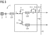
- FIG. 3 is the circuit arrangement of FIG. 1 shown with several possible shorts 4. The differences are that the shorts 4 should be present at different fault locations F.
- the circuit breaker LS2 is not yet open, so that in each case the back-up function of the circuit breaker LS1 is activated for the present below the threshold 6 possible short circuits, since the short-circuit current is large enough.
- the circuit breaker LS1 triggers for the short circuits 4 at the fault locations F1, F3 after the predetermined time, since these short circuits between the upstream and downstream circuit breakers LS1 and LS2, LSn are, and consequently none of the downstream circuit breaker LS1, LSn turns off.
- the circuit breaker LS1 In the case of the short circuits 4 at the fault locations F2.1, F2.2, F2.3, the circuit breaker LS1, after detecting the activation of its back-up function or after recognizing that the outgoing-side impedance is smaller than a predetermined threshold value, checks the time switch Course of the impedance, ie the ohmic resistance R. This has here an exponential but not by a switching arc 5 of a downstream circuit breaker LS2, LSn conditional on exponential history. He recognizes this by the fact that this exponential curve is not a given time value (here 1 ms) away from the zero crossing (since this is the case only with switching arcs 5).
- the circuit breaker LS2 responsible here does not pull a switching arc 5, ie it is not about to open, the circuit breaker LS1 opens (completely) after a predetermined current-dependent time has elapsed. Such a situation can occur, for example, in that the circuit breaker LS2 is defective.
- the circuit breaker LS1 is dependent on the activation of its back-up function, since the impedance measured by the circuit breaker LS1 is no longer in its impedance and thus effective range (ie the fault location F2.3 lies in the FIGS. 1 and 3 outside the area 6a).
Landscapes
- Keying Circuit Devices (AREA)
- Emergency Protection Circuit Devices (AREA)
Claims (4)
- Procédé de déclenchement sélectif d'un disjoncteur monté en amont (LS1) et d'au moins un disjoncteur (LS2, LSn) monté en aval de celui-ci,
le disjoncteur monté en amont (LS1) surveillant si l'au moins un disjoncteur monté en aval (LS2, LSn) est déjà en train de s'ouvrir, en formant un arc de coupure (5), suite à un court-circuit (4) survenu en arrière du disjoncteur monté en aval (LS2, LSn), et
le disjoncteur monté en amont (LS1) lui-même ne déclenchant pas lorsqu'il détecte l'arc de coupure (5) côté sortie,
caractérisé en ce que l'arc de coupure (5) existe, pour le disjoncteur monté en amont (LS1), lorsque la résistance ohmique (R) de la boucle de court-circuit formée par le court-circuit (4), côté sortie du point de vue du disjoncteur monté en amont (LS1), présente une courbe exponentielle dans le temps. - Procédé selon la revendication 1,
caractérisé en ce que cette courbe exponentielle passe à chaque fois plus loin du passage par zéro du courant alternatif (I) que ne l'est une valeur temporelle prédéfinie. - Procédé selon la revendication 1 ou 2,
caractérisé en ce que le disjoncteur monté en amont (LS1) présente une fonction de secours et surveille cette fonction de secours ainsi que l'impédance côté sortie,
en ce que la survenue, côté sortie, d'un arc de coupure (5) n'est surveillée pour une durée prédéfinie qu'après activation de la fonction de secours et/ou lorsque l'impédance côté sortie se trouve dans un domaine d'impédance prédéfini et le disjoncteur monté en amont (LS1) déclenche lorsqu'aucun arc de coupure (5) ne se produit dans la durée prédéfinie. - Procédé selon la revendication 3, caractérisé en ce que la durée prédéfinie est fonction du courant.
Applications Claiming Priority (2)
| Application Number | Priority Date | Filing Date | Title |
|---|---|---|---|
| DE200710021270 DE102007021270A1 (de) | 2007-05-03 | 2007-05-03 | Verfahren zum selektiven Auslösen von Leistungsschaltern |
| PCT/EP2008/055310 WO2008135479A1 (fr) | 2007-05-03 | 2008-04-30 | Procédé de déclenchement sélectif d'interrupteurs de puissance |
Publications (2)
| Publication Number | Publication Date |
|---|---|
| EP2143184A1 EP2143184A1 (fr) | 2010-01-13 |
| EP2143184B1 true EP2143184B1 (fr) | 2016-06-15 |
Family
ID=39707947
Family Applications (1)
| Application Number | Title | Priority Date | Filing Date |
|---|---|---|---|
| EP08736632.4A Not-in-force EP2143184B1 (fr) | 2007-05-03 | 2008-04-30 | Procédé de déclenchement sélectif d'interrupteurs de puissance |
Country Status (3)
| Country | Link |
|---|---|
| EP (1) | EP2143184B1 (fr) |
| DE (1) | DE102007021270A1 (fr) |
| WO (1) | WO2008135479A1 (fr) |
Families Citing this family (4)
| Publication number | Priority date | Publication date | Assignee | Title |
|---|---|---|---|---|
| DE102010042609A1 (de) * | 2010-10-19 | 2012-04-19 | Siemens Aktiengesellschaft | Verfahren für eine Anordnung zur Stromverteilung mit einer Einspeisung und nachfolgend mindestens zwei Schaltern mit selektiven Eigenschaften |
| DE102011082339A1 (de) * | 2011-09-08 | 2013-03-14 | Siemens Aktiengesellschaft | Anordnung zur Stromverteilung mit zwei miteinander verbundenen Schaltern, insbesondere Leistungsschaltern für Niederspannungen |
| DE102016209443B4 (de) * | 2016-05-31 | 2021-06-10 | Siemens Aktiengesellschaft | Störlichtbogenerkennungseinheit |
| DE102022202653A1 (de) * | 2022-03-17 | 2023-09-21 | Siemens Aktiengesellschaft | Verfahren zum Backup-Schutz |
Family Cites Families (2)
| Publication number | Priority date | Publication date | Assignee | Title |
|---|---|---|---|---|
| FR2791823B1 (fr) * | 1999-03-30 | 2001-05-11 | Electricite De France | Dispositif et procede de protection d'une ligne d'un reseau de lignes d'alimentation en energie electrique |
| EP1869746A1 (fr) * | 2005-04-15 | 2007-12-26 | Siemens Aktiengesellschaft | Procede et systeme pour augmenter et garantir la selectivite d'un dispositif de commutation dans un groupe de dispositifs de commutation et utilisation dudit systeme lors de la commutation dans des circuits electriques |
-
2007
- 2007-05-03 DE DE200710021270 patent/DE102007021270A1/de not_active Withdrawn
-
2008
- 2008-04-30 WO PCT/EP2008/055310 patent/WO2008135479A1/fr not_active Ceased
- 2008-04-30 EP EP08736632.4A patent/EP2143184B1/fr not_active Not-in-force
Also Published As
| Publication number | Publication date |
|---|---|
| WO2008135479A1 (fr) | 2008-11-13 |
| DE102007021270A1 (de) | 2008-11-06 |
| EP2143184A1 (fr) | 2010-01-13 |
Similar Documents
| Publication | Publication Date | Title |
|---|---|---|
| EP2291895B1 (fr) | Procédé de déclenchement sélectif de disjoncteurs en cas de court-circuit | |
| DE102014204038A1 (de) | Verfahren und Vorrichtungen zur selektiven Isolationsüberwachung in ungeerdeten IT-Stromversorgungssystemen | |
| DE102014005524B4 (de) | Unterbrechung eines Stromes | |
| EP1386381A1 (fr) | Disjoncteur a interrupteur electronique et circuit de derivation | |
| EP3555982B1 (fr) | Détecteur de surintensité et de court-circuit | |
| DE102010063419A1 (de) | Verfahren zum Detektieren von Störlichtbogenereignissen durch einen Fehlerzähler und Vorrichtung | |
| EP2549612A2 (fr) | Procédé de blocage d'un interrupteur | |
| AT503541A1 (de) | Schalteinrichtung | |
| EP2143184B1 (fr) | Procédé de déclenchement sélectif d'interrupteurs de puissance | |
| DE10032655A1 (de) | Elektrischer Überstromauslöser für einen Niederspannungs-Leistungsschalter | |
| DE69832654T2 (de) | Selektiver elektronischer Auslöser, Lastschalter mit einem solchen Auslöser und ein selektives Auslöseverfahren | |
| DE102011120466B4 (de) | Elektronischer Schutzschalter und Verfahren zur Betätigung des Schutzschalters | |
| DE69122078T2 (de) | Leistungseinführungssystem | |
| DE102010042609A1 (de) | Verfahren für eine Anordnung zur Stromverteilung mit einer Einspeisung und nachfolgend mindestens zwei Schaltern mit selektiven Eigenschaften | |
| DE102011005563B4 (de) | Verfahren und Vorrichtung zur Umschaltung von Stromeinspeisungen | |
| EP3347959B1 (fr) | Dispositif de coupure sûre côté réseau, indépendamment d'appareils de distribution et de fusibles auxiliaires, de moyens de protection contre les surtensions en cas d'états de fonctionnement critiques | |
| DE10117372B4 (de) | Schutzeinrichtung, Schutzanordnung und Schutzverfahren für eine elektrische Leitung | |
| EP2548214B1 (fr) | Disjoncteur à courant de défaut | |
| EP0848471A2 (fr) | Dispositif de protection contre les courants de défaut | |
| EP2672595B1 (fr) | Agencement de circuit et procédé destinés à la coupure du courant continu | |
| DE102011082342A1 (de) | Anordnung zur Stromverteilung mit zwei miteinander verbundenen Schaltern, insbesondere Leistungsschaltern für Niederspannungen | |
| DE19927030A1 (de) | Leistungsschalter mit einem elektronischen, mikroprozessorgesteuerten Auslöser und einer Bypass-Schaltung | |
| DE102011080826A1 (de) | Verfahren zum Ermitteln der Lichtbogenleistung eines Schalters, Verfahren zum Auslösen eines Schalters anhand der Lichtbogenleistung und Verfahren zur Ermittlung der Belastung der Kontakte eines Schalters anhand der Lichtbogenenergie | |
| DE102011082339A1 (de) | Anordnung zur Stromverteilung mit zwei miteinander verbundenen Schaltern, insbesondere Leistungsschaltern für Niederspannungen | |
| DE10062280A1 (de) | Sicherheitsschaltung für eine elektrische und/oder elektronische Steuerungsschaltung eines elektrischen Gerätes |
Legal Events
| Date | Code | Title | Description |
|---|---|---|---|
| PUAI | Public reference made under article 153(3) epc to a published international application that has entered the european phase |
Free format text: ORIGINAL CODE: 0009012 |
|
| 17P | Request for examination filed |
Effective date: 20091023 |
|
| AK | Designated contracting states |
Kind code of ref document: A1 Designated state(s): AT BE BG CH CY CZ DE DK EE ES FI FR GB GR HR HU IE IS IT LI LT LU LV MC MT NL NO PL PT RO SE SI SK TR |
|
| DAX | Request for extension of the european patent (deleted) | ||
| RAP1 | Party data changed (applicant data changed or rights of an application transferred) |
Owner name: SIEMENS AKTIENGESELLSCHAFT |
|
| 17Q | First examination report despatched |
Effective date: 20150323 |
|
| GRAP | Despatch of communication of intention to grant a patent |
Free format text: ORIGINAL CODE: EPIDOSNIGR1 |
|
| RIC1 | Information provided on ipc code assigned before grant |
Ipc: H02H 7/26 20060101AFI20151207BHEP Ipc: H02H 7/30 20060101ALI20151207BHEP |
|
| INTG | Intention to grant announced |
Effective date: 20160107 |
|
| GRAS | Grant fee paid |
Free format text: ORIGINAL CODE: EPIDOSNIGR3 |
|
| GRAA | (expected) grant |
Free format text: ORIGINAL CODE: 0009210 |
|
| AK | Designated contracting states |
Kind code of ref document: B1 Designated state(s): AT BE BG CH CY CZ DE DK EE ES FI FR GB GR HR HU IE IS IT LI LT LU LV MC MT NL NO PL PT RO SE SI SK TR |
|
| REG | Reference to a national code |
Ref country code: CH Ref legal event code: EP Ref country code: GB Ref legal event code: FG4D Free format text: NOT ENGLISH |
|
| REG | Reference to a national code |
Ref country code: IE Ref legal event code: FG4D Free format text: LANGUAGE OF EP DOCUMENT: GERMAN |
|
| REG | Reference to a national code |
Ref country code: AT Ref legal event code: REF Ref document number: 806940 Country of ref document: AT Kind code of ref document: T Effective date: 20160715 |
|
| REG | Reference to a national code |
Ref country code: DE Ref legal event code: R096 Ref document number: 502008014304 Country of ref document: DE |
|
| REG | Reference to a national code |
Ref country code: LT Ref legal event code: MG4D |
|
| REG | Reference to a national code |
Ref country code: NL Ref legal event code: MP Effective date: 20160615 |
|
| PG25 | Lapsed in a contracting state [announced via postgrant information from national office to epo] |
Ref country code: NO Free format text: LAPSE BECAUSE OF FAILURE TO SUBMIT A TRANSLATION OF THE DESCRIPTION OR TO PAY THE FEE WITHIN THE PRESCRIBED TIME-LIMIT Effective date: 20160915 Ref country code: LT Free format text: LAPSE BECAUSE OF FAILURE TO SUBMIT A TRANSLATION OF THE DESCRIPTION OR TO PAY THE FEE WITHIN THE PRESCRIBED TIME-LIMIT Effective date: 20160615 Ref country code: FI Free format text: LAPSE BECAUSE OF FAILURE TO SUBMIT A TRANSLATION OF THE DESCRIPTION OR TO PAY THE FEE WITHIN THE PRESCRIBED TIME-LIMIT Effective date: 20160615 |
|
| PG25 | Lapsed in a contracting state [announced via postgrant information from national office to epo] |
Ref country code: GR Free format text: LAPSE BECAUSE OF FAILURE TO SUBMIT A TRANSLATION OF THE DESCRIPTION OR TO PAY THE FEE WITHIN THE PRESCRIBED TIME-LIMIT Effective date: 20160916 Ref country code: NL Free format text: LAPSE BECAUSE OF FAILURE TO SUBMIT A TRANSLATION OF THE DESCRIPTION OR TO PAY THE FEE WITHIN THE PRESCRIBED TIME-LIMIT Effective date: 20160615 Ref country code: LV Free format text: LAPSE BECAUSE OF FAILURE TO SUBMIT A TRANSLATION OF THE DESCRIPTION OR TO PAY THE FEE WITHIN THE PRESCRIBED TIME-LIMIT Effective date: 20160615 Ref country code: HR Free format text: LAPSE BECAUSE OF FAILURE TO SUBMIT A TRANSLATION OF THE DESCRIPTION OR TO PAY THE FEE WITHIN THE PRESCRIBED TIME-LIMIT Effective date: 20160615 Ref country code: SE Free format text: LAPSE BECAUSE OF FAILURE TO SUBMIT A TRANSLATION OF THE DESCRIPTION OR TO PAY THE FEE WITHIN THE PRESCRIBED TIME-LIMIT Effective date: 20160615 |
|
| PG25 | Lapsed in a contracting state [announced via postgrant information from national office to epo] |
Ref country code: EE Free format text: LAPSE BECAUSE OF FAILURE TO SUBMIT A TRANSLATION OF THE DESCRIPTION OR TO PAY THE FEE WITHIN THE PRESCRIBED TIME-LIMIT Effective date: 20160615 Ref country code: CZ Free format text: LAPSE BECAUSE OF FAILURE TO SUBMIT A TRANSLATION OF THE DESCRIPTION OR TO PAY THE FEE WITHIN THE PRESCRIBED TIME-LIMIT Effective date: 20160615 Ref country code: SK Free format text: LAPSE BECAUSE OF FAILURE TO SUBMIT A TRANSLATION OF THE DESCRIPTION OR TO PAY THE FEE WITHIN THE PRESCRIBED TIME-LIMIT Effective date: 20160615 Ref country code: RO Free format text: LAPSE BECAUSE OF FAILURE TO SUBMIT A TRANSLATION OF THE DESCRIPTION OR TO PAY THE FEE WITHIN THE PRESCRIBED TIME-LIMIT Effective date: 20160615 Ref country code: IS Free format text: LAPSE BECAUSE OF FAILURE TO SUBMIT A TRANSLATION OF THE DESCRIPTION OR TO PAY THE FEE WITHIN THE PRESCRIBED TIME-LIMIT Effective date: 20161015 |
|
| PG25 | Lapsed in a contracting state [announced via postgrant information from national office to epo] |
Ref country code: PT Free format text: LAPSE BECAUSE OF FAILURE TO SUBMIT A TRANSLATION OF THE DESCRIPTION OR TO PAY THE FEE WITHIN THE PRESCRIBED TIME-LIMIT Effective date: 20161017 Ref country code: PL Free format text: LAPSE BECAUSE OF FAILURE TO SUBMIT A TRANSLATION OF THE DESCRIPTION OR TO PAY THE FEE WITHIN THE PRESCRIBED TIME-LIMIT Effective date: 20160615 Ref country code: ES Free format text: LAPSE BECAUSE OF FAILURE TO SUBMIT A TRANSLATION OF THE DESCRIPTION OR TO PAY THE FEE WITHIN THE PRESCRIBED TIME-LIMIT Effective date: 20160615 |
|
| REG | Reference to a national code |
Ref country code: DE Ref legal event code: R097 Ref document number: 502008014304 Country of ref document: DE |
|
| PLBE | No opposition filed within time limit |
Free format text: ORIGINAL CODE: 0009261 |
|
| STAA | Information on the status of an ep patent application or granted ep patent |
Free format text: STATUS: NO OPPOSITION FILED WITHIN TIME LIMIT |
|
| REG | Reference to a national code |
Ref country code: FR Ref legal event code: PLFP Year of fee payment: 10 |
|
| 26N | No opposition filed |
Effective date: 20170316 |
|
| PG25 | Lapsed in a contracting state [announced via postgrant information from national office to epo] |
Ref country code: DK Free format text: LAPSE BECAUSE OF FAILURE TO SUBMIT A TRANSLATION OF THE DESCRIPTION OR TO PAY THE FEE WITHIN THE PRESCRIBED TIME-LIMIT Effective date: 20160615 |
|
| PG25 | Lapsed in a contracting state [announced via postgrant information from national office to epo] |
Ref country code: SI Free format text: LAPSE BECAUSE OF FAILURE TO SUBMIT A TRANSLATION OF THE DESCRIPTION OR TO PAY THE FEE WITHIN THE PRESCRIBED TIME-LIMIT Effective date: 20160615 |
|
| REG | Reference to a national code |
Ref country code: CH Ref legal event code: NV Representative=s name: SIEMENS SCHWEIZ AG, CH Ref country code: CH Ref legal event code: PCOW Free format text: NEW ADDRESS: WERNER-VON-SIEMENS-STRASSE 1, 80333 MUENCHEN (DE) |
|
| REG | Reference to a national code |
Ref country code: CH Ref legal event code: PL |
|
| GBPC | Gb: european patent ceased through non-payment of renewal fee |
Effective date: 20170430 |
|
| REG | Reference to a national code |
Ref country code: IE Ref legal event code: MM4A |
|
| PG25 | Lapsed in a contracting state [announced via postgrant information from national office to epo] |
Ref country code: MC Free format text: LAPSE BECAUSE OF FAILURE TO SUBMIT A TRANSLATION OF THE DESCRIPTION OR TO PAY THE FEE WITHIN THE PRESCRIBED TIME-LIMIT Effective date: 20160615 |
|
| PG25 | Lapsed in a contracting state [announced via postgrant information from national office to epo] |
Ref country code: GB Free format text: LAPSE BECAUSE OF NON-PAYMENT OF DUE FEES Effective date: 20170430 Ref country code: CH Free format text: LAPSE BECAUSE OF NON-PAYMENT OF DUE FEES Effective date: 20170430 Ref country code: LI Free format text: LAPSE BECAUSE OF NON-PAYMENT OF DUE FEES Effective date: 20170430 Ref country code: LU Free format text: LAPSE BECAUSE OF NON-PAYMENT OF DUE FEES Effective date: 20170430 |
|
| REG | Reference to a national code |
Ref country code: BE Ref legal event code: MM Effective date: 20170430 |
|
| REG | Reference to a national code |
Ref country code: FR Ref legal event code: PLFP Year of fee payment: 11 |
|
| PG25 | Lapsed in a contracting state [announced via postgrant information from national office to epo] |
Ref country code: IE Free format text: LAPSE BECAUSE OF NON-PAYMENT OF DUE FEES Effective date: 20170430 |
|
| PG25 | Lapsed in a contracting state [announced via postgrant information from national office to epo] |
Ref country code: BE Free format text: LAPSE BECAUSE OF NON-PAYMENT OF DUE FEES Effective date: 20170430 |
|
| REG | Reference to a national code |
Ref country code: AT Ref legal event code: MM01 Ref document number: 806940 Country of ref document: AT Kind code of ref document: T Effective date: 20170430 |
|
| PG25 | Lapsed in a contracting state [announced via postgrant information from national office to epo] |
Ref country code: AT Free format text: LAPSE BECAUSE OF NON-PAYMENT OF DUE FEES Effective date: 20170430 |
|
| PGFP | Annual fee paid to national office [announced via postgrant information from national office to epo] |
Ref country code: IT Payment date: 20180423 Year of fee payment: 11 Ref country code: FR Payment date: 20180412 Year of fee payment: 11 |
|
| PG25 | Lapsed in a contracting state [announced via postgrant information from national office to epo] |
Ref country code: MT Free format text: LAPSE BECAUSE OF FAILURE TO SUBMIT A TRANSLATION OF THE DESCRIPTION OR TO PAY THE FEE WITHIN THE PRESCRIBED TIME-LIMIT Effective date: 20160615 |
|
| PG25 | Lapsed in a contracting state [announced via postgrant information from national office to epo] |
Ref country code: HU Free format text: LAPSE BECAUSE OF FAILURE TO SUBMIT A TRANSLATION OF THE DESCRIPTION OR TO PAY THE FEE WITHIN THE PRESCRIBED TIME-LIMIT; INVALID AB INITIO Effective date: 20080430 |
|
| PGFP | Annual fee paid to national office [announced via postgrant information from national office to epo] |
Ref country code: DE Payment date: 20190617 Year of fee payment: 12 |
|
| PG25 | Lapsed in a contracting state [announced via postgrant information from national office to epo] |
Ref country code: BG Free format text: LAPSE BECAUSE OF FAILURE TO SUBMIT A TRANSLATION OF THE DESCRIPTION OR TO PAY THE FEE WITHIN THE PRESCRIBED TIME-LIMIT Effective date: 20160615 |
|
| PG25 | Lapsed in a contracting state [announced via postgrant information from national office to epo] |
Ref country code: CY Free format text: LAPSE BECAUSE OF NON-PAYMENT OF DUE FEES Effective date: 20160615 |
|
| PG25 | Lapsed in a contracting state [announced via postgrant information from national office to epo] |
Ref country code: TR Free format text: LAPSE BECAUSE OF FAILURE TO SUBMIT A TRANSLATION OF THE DESCRIPTION OR TO PAY THE FEE WITHIN THE PRESCRIBED TIME-LIMIT Effective date: 20160615 |
|
| PG25 | Lapsed in a contracting state [announced via postgrant information from national office to epo] |
Ref country code: IT Free format text: LAPSE BECAUSE OF NON-PAYMENT OF DUE FEES Effective date: 20190430 |
|
| PG25 | Lapsed in a contracting state [announced via postgrant information from national office to epo] |
Ref country code: FR Free format text: LAPSE BECAUSE OF NON-PAYMENT OF DUE FEES Effective date: 20190430 |
|
| REG | Reference to a national code |
Ref country code: DE Ref legal event code: R119 Ref document number: 502008014304 Country of ref document: DE |
|
| PG25 | Lapsed in a contracting state [announced via postgrant information from national office to epo] |
Ref country code: DE Free format text: LAPSE BECAUSE OF NON-PAYMENT OF DUE FEES Effective date: 20201103 |