EP2143306B1 - Elektrode für plasmaerzeuger - Google Patents
Elektrode für plasmaerzeuger Download PDFInfo
- Publication number
- EP2143306B1 EP2143306B1 EP08718192A EP08718192A EP2143306B1 EP 2143306 B1 EP2143306 B1 EP 2143306B1 EP 08718192 A EP08718192 A EP 08718192A EP 08718192 A EP08718192 A EP 08718192A EP 2143306 B1 EP2143306 B1 EP 2143306B1
- Authority
- EP
- European Patent Office
- Prior art keywords
- electrode
- slot
- electrode according
- plasma
- closed
- Prior art date
- Legal status (The legal status is an assumption and is not a legal conclusion. Google has not performed a legal analysis and makes no representation as to the accuracy of the status listed.)
- Not-in-force
Links
- 210000002381 plasma Anatomy 0.000 claims abstract description 39
- 239000002184 metal Substances 0.000 claims abstract description 14
- 230000005284 excitation Effects 0.000 claims abstract description 4
- 239000004020 conductor Substances 0.000 claims description 11
- 239000007789 gas Substances 0.000 claims description 10
- 238000000034 method Methods 0.000 claims description 6
- 238000007599 discharging Methods 0.000 claims 1
- 230000005684 electric field Effects 0.000 description 4
- 230000001419 dependent effect Effects 0.000 description 2
- 238000005234 chemical deposition Methods 0.000 description 1
- 238000005202 decontamination Methods 0.000 description 1
- 230000003588 decontaminative effect Effects 0.000 description 1
- 230000000694 effects Effects 0.000 description 1
- 230000005670 electromagnetic radiation Effects 0.000 description 1
- 238000005530 etching Methods 0.000 description 1
- 235000013305 food Nutrition 0.000 description 1
- 239000000463 material Substances 0.000 description 1
- 230000000149 penetrating effect Effects 0.000 description 1
- 229920000642 polymer Polymers 0.000 description 1
- 230000000135 prohibitive effect Effects 0.000 description 1
- 230000005855 radiation Effects 0.000 description 1
- 238000004062 sedimentation Methods 0.000 description 1
- 238000013022 venting Methods 0.000 description 1
Images

Classifications
-
- H—ELECTRICITY
- H05—ELECTRIC TECHNIQUES NOT OTHERWISE PROVIDED FOR
- H05H—PLASMA TECHNIQUE; PRODUCTION OF ACCELERATED ELECTRICALLY-CHARGED PARTICLES OR OF NEUTRONS; PRODUCTION OR ACCELERATION OF NEUTRAL MOLECULAR OR ATOMIC BEAMS
- H05H1/00—Generating plasma; Handling plasma
- H05H1/24—Generating plasma
- H05H1/46—Generating plasma using applied electromagnetic fields, e.g. high frequency or microwave energy
-
- H—ELECTRICITY
- H05—ELECTRIC TECHNIQUES NOT OTHERWISE PROVIDED FOR
- H05H—PLASMA TECHNIQUE; PRODUCTION OF ACCELERATED ELECTRICALLY-CHARGED PARTICLES OR OF NEUTRONS; PRODUCTION OR ACCELERATION OF NEUTRAL MOLECULAR OR ATOMIC BEAMS
- H05H1/00—Generating plasma; Handling plasma
- H05H1/24—Generating plasma
- H05H1/46—Generating plasma using applied electromagnetic fields, e.g. high frequency or microwave energy
- H05H1/461—Microwave discharges
- H05H1/463—Microwave discharges using antennas or applicators
-
- H—ELECTRICITY
- H05—ELECTRIC TECHNIQUES NOT OTHERWISE PROVIDED FOR
- H05H—PLASMA TECHNIQUE; PRODUCTION OF ACCELERATED ELECTRICALLY-CHARGED PARTICLES OR OF NEUTRONS; PRODUCTION OR ACCELERATION OF NEUTRAL MOLECULAR OR ATOMIC BEAMS
- H05H2240/00—Testing
- H05H2240/10—Testing at atmospheric pressure
-
- H—ELECTRICITY
- H05—ELECTRIC TECHNIQUES NOT OTHERWISE PROVIDED FOR
- H05H—PLASMA TECHNIQUE; PRODUCTION OF ACCELERATED ELECTRICALLY-CHARGED PARTICLES OR OF NEUTRONS; PRODUCTION OR ACCELERATION OF NEUTRAL MOLECULAR OR ATOMIC BEAMS
- H05H2245/00—Applications of plasma devices
- H05H2245/30—Medical applications
- H05H2245/34—Skin treatments, e.g. disinfection or wound treatment
-
- H—ELECTRICITY
- H05—ELECTRIC TECHNIQUES NOT OTHERWISE PROVIDED FOR
- H05H—PLASMA TECHNIQUE; PRODUCTION OF ACCELERATED ELECTRICALLY-CHARGED PARTICLES OR OF NEUTRONS; PRODUCTION OR ACCELERATION OF NEUTRAL MOLECULAR OR ATOMIC BEAMS
- H05H2277/00—Applications of particle accelerators
- H05H2277/10—Medical devices
- H05H2277/11—Radiotherapy
Definitions
- the invention relates to an electrode for a plasma generator for producing plasmas at atmospheric pressure or atmospheric pressures by excitation with microwaves.
- Plasmas are used in many sedimentation, etching and layering processes.
- vacuum-operated plasma reactors Apart from the costs associated with vacuum-operated plasma reactors, the use of vacuum is often prohibitive in this area, so the use of plasma at atmospheric pressure is a prerequisite. Also, treatment of vacuum sensitive materials such as certain polymers or sensitive foods is possible with low temperature plasmas at atmospheric or near atmospheric pressure.
- the invention has for its object to provide an electrode for a plasma generator, which ignites safely especially in the near-atmospheric pressure range at low power and is able to generate a plasma with sufficiently high density, so that a penetrating gas flow is activated with high efficiency.
- the electrode consists of a metal strip, in the longitudinal direction of which at least one slot is introduced having a length which is one or more times a quarter of the wavelength of the open circuit voltage of the microwave, so that form at least two partial electrodes, wherein the voltage supply to the sub-electrodes takes place in the region of the closed slot end or the closed slot ends.
- the structure of the electrode exploits frequency-dependent, resonant properties of the structure and generates at a defined location a high electric field strength, at which the ignition of the plasma is made possible.
- the strong field is typically formed by at least two electrodes physically close to each other. If electric power in the form of microwaves is introduced into the structure at a suitable point, a high alternating potential difference arises at the end of the slot. Due to the short distance between the opposing electrodes, the resulting field strength is very high. At the point of the highest electric field, the ignition of a plasma at atmospheric pressure or at atmospheric pressure is possible with sufficiently high feed power. After ignition, only a fraction of the required ignition power is required to operate.
- the frequency of the feed-in power depends on the physical dimensions of the electrode. In particular, the length of the slot has a significant influence on the frequency and is approximately the multiple of the quarter wavelength.
- the feed takes place in the case of a unilaterally open slot, for example by a coaxial line, wherein the Inner conductor is guided on one side of the slot to the point in which there is approximately in idle adjustment.
- the electrode is bent in this case U-shaped or circular.
- the feed takes place in the latter case, for example, by a coaxial line, wherein the inner conductor branches in a T-shape and is guided on both sides in the region of the two slot ends to the electrode.
- the electrode is preferably powered by a free-running oscillator circuit, the electrode itself being the frequency-determining element.
- the oscillator circuit can be constructed integrated with the electrode.
- the electrode may be preferred for medical treatment purposes, especially the treatment of human skin, as well be used for modifying the surface energy of workpieces or for plasma-chemical deposition of layers.
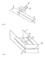
- Fig. 1 shows an example of a resonator of a plasma generator.
- a slot 2 is introduced in a metal strip 1, which serves as an electrode.
- the slot 2 separates the sheet metal strip 1 into two sub-electrodes 3, which generate a high electric field strength during operation with a high-frequency voltage which is conducted via the inner conductor 4 of a coaxial line 5 to the sheet metal strip 1.
- the slot 2 is typically ⁇ / 4 long. In a real running design for a supply voltage with a frequency of 2 GHz, this resulted in a slot 2 of 37.5 mm. Its width was 0.1 mm.
- the inner conductor 4 of the coaxial line 5 is guided in the region of the slot end to the outside edge of the metal strip 1, to a point at the resonance is generated with an oscillator.
- the outer conductor 6 of the coaxial line 5 is guided on the opposite side of the metal strip 1 at its outer edge.
- Fig. 2 shows an electrode of a U-shaped bent sheet metal strip 1 with a slot 2.
- the slot 2 in this case ⁇ / 2 long.
- the inner conductor 4 of the coaxial line 5 is branched in a T-shape and guided on the two opposite sides of the sheet metal strip 1 in the region of the slot end.
- the outer conductor 6 is connected to the opposite sides of the sheet metal strip 1.
- the highest field strength arises in this embodiment in the middle of the slot 2, that is at the leading edge of the sheet metal strip 1. After the ignition of the plasma at this point, the plasma expands at least over the entire region of the front edge of the sheet metal strip 1.
- Fig. 3 schematically shows the structure of a completed by a housing 7 resonator.
- the housing 7 (shown here in the quasi-open state) has a reflective effect and thus prevents electromagnetic radiation to the outside.
- a gas feed line 8 is provided in the rear housing wall and a slot-shaped gas outlet 9 is provided in the front wall.
Landscapes
- Physics & Mathematics (AREA)
- Engineering & Computer Science (AREA)
- Plasma & Fusion (AREA)
- Electromagnetism (AREA)
- Spectroscopy & Molecular Physics (AREA)
- Plasma Technology (AREA)
- Apparatus For Disinfection Or Sterilisation (AREA)
Description
- Die Erfindung betrifft eine Elektrode für einen Plasmaerzeuger zur Erzeugung von Plasmen bei Atmosphärendruck oder atmosphärennahen Drücken durch Anregung mit Mikrowellen.
- Plasmen werden bei vielen Sedimentations-, Ätz- und Schichtbildungsprozessen eingesetzt.
- Jüngste Bestrebungen gehen dahin, geeignete Niedertemperaturplasmen auch unter Nichtvakuum-Bedingungen zu erzeugen. Derartige Reaktoren arbeiten mit Corona-Entladungen oder Glimmentladungen. Eine Übersicht über solche Plasmaerzeuger findet sich in Laroussi, Nonthermal Decontamination of Biological Media by Atmospheric-Pressure Plasmas: Review, Analysis, and Prospects, IEEE Transactions on Plasma Science, Vol. 30, No. 4, August 2002, S. 1409-1415 oder auch in Schütze et al., The Atmospheric-Pressure Plasma Jet: A Review and Comparison to Other Plasma Sources, a.a.O., Vol. 26, No. 6, December 1998. Die hier beschriebenen Plasmareaktoren sollen u. a. für biologische und medizinische Zwecke eingesetzt werden. Abgesehen von den Kosten, die bei Plasmareaktoren entstehen, die unter Vakuum arbeiten, verbietet sich in diesem Bereich oftmals die Anwendung von Unterdruck, so dass hier die Anwendung von Plasma bei Atmosphärendruck eine Voraussetzung ist. Auch eine Behandlung von vakuumempfindlichen Materialien wie bestimmte Polymere oder von empfindlichen Lebensmitteln wird mit Niedertemperaturplasmen bei atmosphärischem oder atmosphärennahem Druck möglich.
- Ein weiteres Beispiel eines Mikrowellen-Plasmaerzeugersbei Atmosphärendruck ist in JAEHO et Al. ; "2.45 GHz microwave-excited atmospheric pressure air microplasmas based on microstripo technology" - Applied Physics Letters - BD 86, Nr.19, 9. Mai 2005, seiten 191504/1-3.
- Für die Plasmaerzeuger müssen Stromversorgungen mit hoher Leistung bereitgehalten werden, wobei die hohe Leistung nur zur Zündung benötigt wird.
- Für den Elektrodenabstand muss immer ein Kompromiss zwischen dem Zündverhalten und dem stabilen Plasmabetrieb geschlossen werden. Für die Zündung optimale kleine Elektrodenabstände führen zu sehr kleinen Plasmavolumina und hoher Punktbelastung der Elektroden. Größere Elektrodenabstände führen zu extrem hohen Zündspannungen und instabilem Plasmaverhalten.
- Der Erfindung liegt die Aufgabe zugrunde, eine Elektrode für einen Plasmaerzeuger anzugeben, die insbesondere im atmosphärennahen Druckbereich bei kleinen Leistungen sicher zündet und ein Plasma mit genügend hoher Dichte zu generieren vermag, sodass ein durchdringender Gasstrom mit hoher Effizienz aktiviert wird.
- Erfindungsgemäß wird die Aufgabe gelöst durch eine Elektrode mit den Merkmalen des Anspruchs 1. Zweckmäßige Ausgestaltungen sind Gegenstand der Unteransprüche.
- Danach besteht die Elektrode aus einem Blechstreifen, in dessen Längsrichtung mindestens ein Schlitz mit einer Länge eingebracht ist, die das Ein- oder Mehrfache eines Viertels der Wellenlänge der Leerlaufspannung der Mikrowelle beträgt, so dass sich mindestens zwei Teilelektroden bilden, wobei die Spannungszuleitung an die Teilelektroden im Bereich des geschlossenen Schlitzendes oder der geschlossenen Schlitzenden erfolgt.
- Bei der erfindungsgemäßen Elektrode gibt es unter Berücksichtigung der Anregungsfrequenz im Leerlauf einen geometrischen Punkt hoher Feldstärke, an dem das Plasma zündet. Bei gezündetem Plasma verändert sich durch die Plasmaimpedanz die Feldverteilung in der Elektrodenstruktur und das Plasma wandert an einen anderen Ort bzw. verbreitert sich innerhalb des Elektrodenschlitzes und breitet sich in einem größeren Volumen aus.
- Die Struktur der Elektrode nutzt frequenzabhängige, resonante Eigenschaften des Aufbaues aus und generiert an definierter Stelle eine hohe elektrische Feldstärke, an der die Zündung des Plasmas ermöglicht wird. Das starke Feld entsteht typischerweise an mindestens zwei Elektroden die sich physikalisch nah gegenüber stehen. Wird nun elektrische Leistung in Form von Mikrowellen an geeigneter Stelle in die Struktur eingebracht, entsteht am Ende des Schlitzes eine hohe alternierende Potentialdifferenz. Durch den geringen Abstand der sich gegenüberstehenden Elektroden ist die resultierende Feldstärke sehr hoch. An der Stelle des höchsten elektrischen Feldes ist, bei genügend hoher Speiseleistung, die Zündung eines Plasmas bei Atmosphärendruck bzw. bei atmosphärennahem Druck möglich. Nach erfolgter Zündung ist zum Betrieb nur ein Bruchteil der erforderlichen Zündleistung nötig. Die Frequenz der Einspeiseleistung ist abhängig von den physikalischen Dimensionen der Elektrode. Besonders die Länge des Schlitzes hat maßgeblichen Einfluss auf die Frequenz und beträgt in etwa das Vielfache der Viertelwellenlänge.
- Die Einspeisung erfolgt im Fall eines einseitig offenen Schlitzes zum Beispiel durch eine Koaxialleitung, wobei der Innenleiter an einer Seite des Schlitzes an die Stelle geführt ist, bei der im Leerlauf in etwa Anpassung herrscht.
- Auch Aufbauten mit beidseitig geschlossenem Schlitz sind nach diesem Prinzip möglich. Das höchste elektrische Feld und somit auch das Plasma entstehen dann in der Mitte des Schlitzes. Zweckmäßig ist die Elektrode in diesem Fall U-förmig oder kreisförmig gebogen.
- Die Einspeisung erfolgt im letztgenannten Fall zum Beispiel durch eine Koaxialleitung, wobei der Innenleiter sich T-förmig verzweigt und auf beiden Seiten im Bereich der beiden Schlitzenden an die Elektrode geführt ist.
- Zum Beispiel für die Behandlung von Prozessgasen ist die Elektrode zweckmäßig von einem Abschirmgehäuse umgeben, in dem sich eine Öffnung zum Zuführen und eine weitere Öffnung zum Herausführen der vom Plasma aktivierten Prozessgase befindet. Die Öffnungen sollten eine solche Größe haben, dass die Abstrahlung von Mikrowellenenergie im zulässigen Bereich bleibt.
- Die Elektrode wird in bevorzugter Weise von einer freilaufenden Oszillatorschaltung versorgt, wobei die Elektrode selbst das die Frequenz bestimmende Element darstellt. Die Oszillatorschaltung kann mit der Elektrode integriert aufgebaut werden.
- Die Elektrode kann bevorzugt für medizinische Behandlungszwecke, insbesondere die Behandlung menschlicher Haut, aber auch zur Modifizierung der Oberflächenenergie von Werkstücken oder zur plasmachemischen Abscheidung von Schichten eingesetzt werden.
- Die Erfindung soll nachstehend anhand zweier Ausführungsbeispiele näher erläutert werden. In den zugehörigen Zeichnungen zeigen
- Fig. 1
- ein Beispiel für eine erfindungsgemäße Elektrode eines Resonators,
- Fig. 2
- ein Beispiel für eine geschlossene Bauform einer Elektrode eines Resonators und
- Fig. 3
- den Resonator gemäß
Fig. 2 in ein Gehäuse eingebet- tet. -
Fig. 1 zeigt ein Beispiel für einen Resonator eines Plasmaerzeugers. In einen Blechstreifen 1, der als Elektrode dient, ist ein Schlitz 2 eingebracht. Der Schlitz 2 trennt den Blechstreifen 1 in zwei Teilelektroden 3 auf, die beim Betrieb mit einer hochfrequenten Spannung, die über den Innenleiter 4 einer Koaxialleitung 5 an den Blechstreifen 1 geführt wird, eine hohe elektrische Feldstärke erzeugen. Der Schlitz 2 ist typischerweise λ/4 lang. Bei einer real ausgeführten Ausführung für eine Versorgungsspannung mit einer Frequenz von 2 GHz ergab sich damit ein Schlitz 2 von 37,5 mm. Seine Breite betrug 0,1 mm. Der Innenleiter 4 der Koaxialleitung 5 ist im Bereich des Schlitzendes an den Außerrand des Blechstreifens 1 geführt, an einen Punkt, an dem Resonanz mit einem Oszillator erzeugt wird. Der Außenleiter 6 der Koaxialleitung 5 ist an der gegenüberliegenden Seite des Blechstreifens 1 an dessen Außenrand geführt. - Nach Anlegen der Versorgungsspannung entsteht am Schlitzende eine hohe Feldstärke, die zum Zünden eines Plasmas bei Atmosphärendruck reicht. Nach dem Zünden bewegt sich das Plasma in den Schlitz 2 hinein und vergrößert sein Volumen, wobei es ein stabiles Verhalten zeigt.
-
Fig. 2 zeigt eine Elektrode aus einem U-förmig gebogenen Blechstreifen 1 mit einem Schlitz 2. Der Schlitz 2 ist in diesem Fall λ/2 lang. Der Innenleiter 4 der Koaxialleitung 5 wird T-förmig verzweigt und an die zwei sich gegenüberstehenden Seiten des Blechstreifens 1 im Bereich des Schlitzendes geführt. Der Außenleiter 6 wird mit den gegenüberliegenden Seiten des Blechstreifens 1 verbunden. Die höchste Feldstärke entsteht bei dieser Ausführungsform in der Mitte des Schlitzes 2, das heißt an der Vorderkante des Blechstreifens 1. Nach dem Zünden des Plasmas an dieser Stelle dehnt sich das Plasma mindestens auf den gesamten Bereich der Vorderkante des Blechstreifens 1 aus. -
Fig. 3 zeigt schematisch den Aufbau eines durch ein Gehäuse 7 komplettierten Resonators. Das Gehäuse 7 (hier im quasi geöffneten Zustand dargestellt) wirkt reflektierend und unterbindet so eine elektromagnetische Abstrahlung nach außen. Um mit diesem Plasmaerzeuger ein Prozessgas zu behandeln, ist in der hinteren Gehäusewand eine Gaszuleitung 8 und in der Vorderwand eine schlitzförmige Gasausleitung 9 vorgesehen. -
- 1
- Blechstreifen
- 2
- Schlitz
- 3
- Teilelektrode
- 4
- Innenleiter
- 5
- Koaxialleitung
- 6
- Außenleiter
- 7
- Gehäuse
- 8
- Gaszuleitung
- 9
- Gasausleitung
Claims (11)
- Elektrode für einen Plasmaerzeuger zur Erzeugung von Plasmen bei Atmosphärendruck oder atmosphärennahen Drücken durch Anregung mit Mikrowellen,
dadurch gekennzeichnet, dass
sie aus einem Blechstreifen (1) besteht, in dessen Längsrichtung mindestens ein Schlitz (2) mit einer Länge eingebracht ist, die das Ein- oder Mehrfache eines Viertels der Wellenlänge der Leerlaufspannung der Mikrowelle beträgt, so dass sich mindestens zwei Teilelektroden (3) bilden, wobei die Spannungszuleitung an die Teilelektroden (3) im Bereich des geschlossenen Schlitzendes oder der geschlossenen Schlitzenden erfolgt. - Elektrode nach Anspruch 1,
dadurch gekennzeichnet, dass
der Schlitz (2) an seinem einen Ende geschlossen, am anderen Ende offen ist. - Elektrode nach Anspruch 1,
dadurch gekennzeichnet, dass
der Schlitz (2) an beiden Seiten geschlossen ist. - Elektrode nach Anspruch 3,
dadurch gekennzeichnet, dass
sie U-förmig gebogen ist. - Elektrode nach Anspruch 3,
dadurch gekennzeichnet, dass
sie kreisförmig gebogen ist. - Elektrode nach Anspruch 1 oder 2,
dadurch gekennzeichnet, dass
sie durch eine koaxiale Einspeisung (5) versorgt wird, wobei der Innenleiter (4) an einer Seite des Schlitzes (2) an die Stelle geführt ist, bei der im Leerlauf in etwa Anpassung herrscht. - Elektrode nach einem der Ansprüche 3 bis 5,
dadurch gekennzeichnet, dass
sie durch eine koaxiale Einspeisung (5) versorgt wird, wobei der Innenleiter (4) sich T-förmig verzweigt und auf beiden Seiten im Bereich der beiden Schlitzenden an die Elektrode geführt ist. - Elektrode nach einem der vorhergehenden Ansprüche,
dadurch gekennzeichnet, dass
sie von einem Abschirmgehäuse (7) umgeben ist. - Elektrode nach Anspruch 8,
dadurch gekennzeichnet, dass
sich in dem Abschirmgehäuse (7) eine Öffnung zum Zuführen von Prozessgasen und eine weitere Öffnung zum Herausführen der vom Plasma aktivierten Prozessgase befindet. - Elektrode nach einem der vorhergehenden Ansprüche,
dadurch gekennzeichnet, dass
sie von einer freilaufenden Oszillatorschaltung versorgt ist, wobei die Elektrode selbst das die Frequenz bestimmende Element darstellt. - Elektrode nach einem der vorhergehenden Ansprüche,
dadurch gekennzeichnet, dass
sie zusammen mit einer Oszillatorschaltung integriert ist.
Applications Claiming Priority (2)
| Application Number | Priority Date | Filing Date | Title |
|---|---|---|---|
| DE102007020419A DE102007020419A1 (de) | 2007-04-27 | 2007-04-27 | Elektrode für Plasmaerzeuger |
| PCT/EP2008/053507 WO2008131997A1 (de) | 2007-04-27 | 2008-03-25 | Elektrode für plasmaerzeuger |
Publications (2)
| Publication Number | Publication Date |
|---|---|
| EP2143306A1 EP2143306A1 (de) | 2010-01-13 |
| EP2143306B1 true EP2143306B1 (de) | 2011-08-17 |
Family
ID=39534997
Family Applications (1)
| Application Number | Title | Priority Date | Filing Date |
|---|---|---|---|
| EP08718192A Not-in-force EP2143306B1 (de) | 2007-04-27 | 2008-03-25 | Elektrode für plasmaerzeuger |
Country Status (7)
| Country | Link |
|---|---|
| US (1) | US8339047B2 (de) |
| EP (1) | EP2143306B1 (de) |
| JP (1) | JP5683262B2 (de) |
| KR (1) | KR101555385B1 (de) |
| AT (1) | ATE521217T1 (de) |
| DE (1) | DE102007020419A1 (de) |
| WO (1) | WO2008131997A1 (de) |
Families Citing this family (2)
| Publication number | Priority date | Publication date | Assignee | Title |
|---|---|---|---|---|
| FR3042091B1 (fr) * | 2015-10-05 | 2017-10-27 | Sairem Soc Pour L'application Ind De La Rech En Electronique Et Micro Ondes | Dispositif elementaire d’application d’une energie micro-onde avec applicateur coaxial |
| KR102190524B1 (ko) * | 2020-02-24 | 2020-12-14 | 이엠코어텍 주식회사 | 저전압 플라즈마 이오나이저 |
Family Cites Families (21)
| Publication number | Priority date | Publication date | Assignee | Title |
|---|---|---|---|---|
| US3848196A (en) * | 1973-11-08 | 1974-11-12 | Rca Corp | Broadband trapatt diode amplifier |
| JPS6011417B2 (ja) * | 1979-10-23 | 1985-03-26 | 株式会社東芝 | ホロ−カソ−ド放電装置 |
| JPS6087200U (ja) * | 1983-11-15 | 1985-06-15 | 新日本無線株式会社 | マイクロ波プラズマ発生装置 |
| JPS62115700A (ja) * | 1985-11-15 | 1987-05-27 | キヤノン株式会社 | 気相励起装置 |
| JPH01109699A (ja) * | 1987-10-23 | 1989-04-26 | Japan Synthetic Rubber Co Ltd | プラズマ処理装置 |
| DE3830430A1 (de) * | 1987-09-11 | 1989-03-23 | Japan Synthetic Rubber Co Ltd | Verfahren zur herstellung von ueberzuegen |
| JPH0719674B2 (ja) * | 1992-06-24 | 1995-03-06 | 徳芳 佐藤 | マイクロ波放電反応装置の電極装置 |
| US5537004A (en) * | 1993-03-06 | 1996-07-16 | Tokyo Electron Limited | Low frequency electron cyclotron resonance plasma processor |
| US5838111A (en) * | 1996-02-27 | 1998-11-17 | Matsushita Electric Industrial Co., Ltd. | Plasma generator with antennas attached to top electrodes |
| US6518703B1 (en) * | 1998-03-16 | 2003-02-11 | Matsushita Electrical Industrial Co., Ltd. | Electrodeless discharge energy supply apparatus and electrodeless discharge lamp device using surface wave transmission line |
| US6350417B1 (en) * | 1998-11-05 | 2002-02-26 | Sharper Image Corporation | Electrode self-cleaning mechanism for electro-kinetic air transporter-conditioner devices |
| JP2000299199A (ja) * | 1999-04-13 | 2000-10-24 | Plasma System Corp | プラズマ発生装置およびプラズマ処理装置 |
| DE19955671B4 (de) * | 1999-11-19 | 2004-07-22 | Muegge Electronic Gmbh | Vorrichtung zur Erzeugung von Plasma |
| US6576202B1 (en) * | 2000-04-21 | 2003-06-10 | Kin-Chung Ray Chiu | Highly efficient compact capacitance coupled plasma reactor/generator and method |
| US6759808B2 (en) * | 2001-10-26 | 2004-07-06 | Board Of Trustees Of Michigan State University | Microwave stripline applicators |
| WO2004062326A2 (en) * | 2002-12-30 | 2004-07-22 | Northeastern University | Low power plasma generator |
| DE10335523B4 (de) * | 2003-07-31 | 2009-04-30 | Koch, Berthold, Dr.-Ing. | Vorrichtung zur Plasmaerregung mit Mikrowellen |
| JP4631046B2 (ja) * | 2004-10-01 | 2011-02-16 | 国立大学法人 東京大学 | マイクロ波励起プラズマ装置及びシステム |
| JP4035568B2 (ja) * | 2004-11-29 | 2008-01-23 | 株式会社エーイーティー | 大気圧大面積プラズマ発生装置 |
| US8216433B2 (en) * | 2006-03-07 | 2012-07-10 | University Of The Ryukyus | Plasma generator and method of generating plasma using the same |
| JP4967784B2 (ja) * | 2007-04-25 | 2012-07-04 | 凸版印刷株式会社 | マイクロ波プラズマ発生装置 |
-
2007
- 2007-04-27 DE DE102007020419A patent/DE102007020419A1/de not_active Withdrawn
-
2008
- 2008-03-25 KR KR1020097022500A patent/KR101555385B1/ko not_active Expired - Fee Related
- 2008-03-25 AT AT08718192T patent/ATE521217T1/de active
- 2008-03-25 WO PCT/EP2008/053507 patent/WO2008131997A1/de not_active Ceased
- 2008-03-25 US US12/451,139 patent/US8339047B2/en not_active Expired - Fee Related
- 2008-03-25 JP JP2010504600A patent/JP5683262B2/ja not_active Expired - Fee Related
- 2008-03-25 EP EP08718192A patent/EP2143306B1/de not_active Not-in-force
Also Published As
| Publication number | Publication date |
|---|---|
| EP2143306A1 (de) | 2010-01-13 |
| KR101555385B1 (ko) | 2015-09-23 |
| JP5683262B2 (ja) | 2015-03-11 |
| ATE521217T1 (de) | 2011-09-15 |
| US8339047B2 (en) | 2012-12-25 |
| US20100171425A1 (en) | 2010-07-08 |
| WO2008131997A1 (de) | 2008-11-06 |
| DE102007020419A1 (de) | 2008-11-06 |
| KR20100015978A (ko) | 2010-02-12 |
| JP2010525534A (ja) | 2010-07-22 |
Similar Documents
| Publication | Publication Date | Title |
|---|---|---|
| DE2952046C2 (de) | Verfahren und Vorrichtung zur Erzeugung einer elektrischen Entladung in einem mit Überschallgeschwindigkeit strömenden Gas | |
| EP1053660B1 (de) | Vorrichtung zur erzeugung eines freien kalten nicht-thermischen plasmastrahles | |
| DE102006019664B4 (de) | Kaltplasma-Handgerät zur Plasma-Behandlung von Oberflächen | |
| DE4340224C2 (de) | Einrichtung zum Erzeugen von Plasma mittels Mikrowellenstrahlung | |
| DE69514733T2 (de) | Koronaquelle zur Erzeugung einer Koronaentladung und Behandlung von fliesfähige Abfallstoffen mit Koronaentladung | |
| DE602004007126T2 (de) | Vorrichtung und verfahren zur bildung eines plasmas | |
| DE19513250C2 (de) | Verfahren und Vorrichtung zur kontinuierlichen Entfernung von Stickoxiden in Abgasen von Verbrennungsmaschinen | |
| EP2849204A1 (de) | Plasmaerzeugungsvorrichtung | |
| EP1290926B1 (de) | Hochfrequenz-plasmaquelle | |
| DE202016008999U1 (de) | Vorrichtung zur Erzeugung eines Plasmas aufweisend einen piezoelektrischer Transformator | |
| EP2143306B1 (de) | Elektrode für plasmaerzeuger | |
| EP1819208B1 (de) | Vorrichtung und Verfahren zur Erzeugung angeregter und/oder ionisierter Teilchen in einem Plasma | |
| EP2502469B1 (de) | Vorrichtung und verfahren zur erzeugung eines plasmas mittels eines wanderwellenresonators | |
| EP1129466B1 (de) | Vorrichtung und verfahren zur erzeugung eines lokalen plasmas durch mikrostrukturelektrodenentladungen mit mikrowellen | |
| EP2751826B1 (de) | Vorrichtung zur erzeugung von thermodynamisch kaltem mikrowellenplasma | |
| DE4337119C2 (de) | VHF-Plasmaquelle | |
| EP1836718B1 (de) | Mikroplasmaarray | |
| DE2917995C2 (de) | Verfahren zur Erzeugung eines laseraktiven Zustandes in einer Gasströmung | |
| EP1252647B1 (de) | Einkoppelanordnung für mikrowellenenergie mit impedanzanpassung | |
| AT504487B1 (de) | Vorrichtung zur erzeugung von plasma oder radikalen mittels mikrowellen | |
| DE19955671B4 (de) | Vorrichtung zur Erzeugung von Plasma | |
| DE4242324A1 (de) | Verfahren und Einrichtung zur Behandlung der Innenwand eines Hohlkörpers mittels eines Mikrowellenplasmas | |
| DE102010043940B4 (de) | Mikrowellen-ICP-Resonator | |
| DE102020100872A1 (de) | Resonator und Leistungsoszillator zum Aufbau einer integrierten Plasmaquelle sowie deren Verwendung | |
| DE3842756A1 (de) | Hochfrequenz-ionenstrahlquelle |
Legal Events
| Date | Code | Title | Description |
|---|---|---|---|
| PUAI | Public reference made under article 153(3) epc to a published international application that has entered the european phase |
Free format text: ORIGINAL CODE: 0009012 |
|
| 17P | Request for examination filed |
Effective date: 20091124 |
|
| AK | Designated contracting states |
Kind code of ref document: A1 Designated state(s): AT BE BG CH CY CZ DE DK EE ES FI FR GB GR HR HU IE IS IT LI LT LU LV MC MT NL NO PL PT RO SE SI SK TR |
|
| DAX | Request for extension of the european patent (deleted) | ||
| GRAP | Despatch of communication of intention to grant a patent |
Free format text: ORIGINAL CODE: EPIDOSNIGR1 |
|
| GRAS | Grant fee paid |
Free format text: ORIGINAL CODE: EPIDOSNIGR3 |
|
| GRAA | (expected) grant |
Free format text: ORIGINAL CODE: 0009210 |
|
| RIN1 | Information on inventor provided before grant (corrected) |
Inventor name: KUEHN, SILVIO Inventor name: GESCHE, ROLAND Inventor name: ANDREI, ANDREEA, CRISTINA Inventor name: BUCHHOLZ, STEPHAN |
|
| AK | Designated contracting states |
Kind code of ref document: B1 Designated state(s): AT BE BG CH CY CZ DE DK EE ES FI FR GB GR HR HU IE IS IT LI LT LU LV MC MT NL NO PL PT RO SE SI SK TR |
|
| REG | Reference to a national code |
Ref country code: GB Ref legal event code: FG4D Free format text: NOT ENGLISH |
|
| REG | Reference to a national code |
Ref country code: CH Ref legal event code: EP |
|
| REG | Reference to a national code |
Ref country code: IE Ref legal event code: FG4D Free format text: LANGUAGE OF EP DOCUMENT: GERMAN |
|
| REG | Reference to a national code |
Ref country code: DE Ref legal event code: R096 Ref document number: 502008004526 Country of ref document: DE Effective date: 20111117 |
|
| REG | Reference to a national code |
Ref country code: CH Ref legal event code: NV Representative=s name: PATENTANWAELTE SCHAAD, BALASS, MENZL & PARTNER AG |
|
| REG | Reference to a national code |
Ref country code: NL Ref legal event code: VDEP Effective date: 20110817 |
|
| LTIE | Lt: invalidation of european patent or patent extension |
Effective date: 20110817 |
|
| PG25 | Lapsed in a contracting state [announced via postgrant information from national office to epo] |
Ref country code: LT Free format text: LAPSE BECAUSE OF FAILURE TO SUBMIT A TRANSLATION OF THE DESCRIPTION OR TO PAY THE FEE WITHIN THE PRESCRIBED TIME-LIMIT Effective date: 20110817 Ref country code: NO Free format text: LAPSE BECAUSE OF FAILURE TO SUBMIT A TRANSLATION OF THE DESCRIPTION OR TO PAY THE FEE WITHIN THE PRESCRIBED TIME-LIMIT Effective date: 20111117 Ref country code: PT Free format text: LAPSE BECAUSE OF FAILURE TO SUBMIT A TRANSLATION OF THE DESCRIPTION OR TO PAY THE FEE WITHIN THE PRESCRIBED TIME-LIMIT Effective date: 20111219 Ref country code: SE Free format text: LAPSE BECAUSE OF FAILURE TO SUBMIT A TRANSLATION OF THE DESCRIPTION OR TO PAY THE FEE WITHIN THE PRESCRIBED TIME-LIMIT Effective date: 20110817 Ref country code: NL Free format text: LAPSE BECAUSE OF FAILURE TO SUBMIT A TRANSLATION OF THE DESCRIPTION OR TO PAY THE FEE WITHIN THE PRESCRIBED TIME-LIMIT Effective date: 20110817 Ref country code: IS Free format text: LAPSE BECAUSE OF FAILURE TO SUBMIT A TRANSLATION OF THE DESCRIPTION OR TO PAY THE FEE WITHIN THE PRESCRIBED TIME-LIMIT Effective date: 20111217 Ref country code: FI Free format text: LAPSE BECAUSE OF FAILURE TO SUBMIT A TRANSLATION OF THE DESCRIPTION OR TO PAY THE FEE WITHIN THE PRESCRIBED TIME-LIMIT Effective date: 20110817 |
|
| PG25 | Lapsed in a contracting state [announced via postgrant information from national office to epo] |
Ref country code: SI Free format text: LAPSE BECAUSE OF FAILURE TO SUBMIT A TRANSLATION OF THE DESCRIPTION OR TO PAY THE FEE WITHIN THE PRESCRIBED TIME-LIMIT Effective date: 20110817 Ref country code: GR Free format text: LAPSE BECAUSE OF FAILURE TO SUBMIT A TRANSLATION OF THE DESCRIPTION OR TO PAY THE FEE WITHIN THE PRESCRIBED TIME-LIMIT Effective date: 20111118 Ref country code: PL Free format text: LAPSE BECAUSE OF FAILURE TO SUBMIT A TRANSLATION OF THE DESCRIPTION OR TO PAY THE FEE WITHIN THE PRESCRIBED TIME-LIMIT Effective date: 20110817 Ref country code: CY Free format text: LAPSE BECAUSE OF FAILURE TO SUBMIT A TRANSLATION OF THE DESCRIPTION OR TO PAY THE FEE WITHIN THE PRESCRIBED TIME-LIMIT Effective date: 20110817 Ref country code: LV Free format text: LAPSE BECAUSE OF FAILURE TO SUBMIT A TRANSLATION OF THE DESCRIPTION OR TO PAY THE FEE WITHIN THE PRESCRIBED TIME-LIMIT Effective date: 20110817 |
|
| REG | Reference to a national code |
Ref country code: IE Ref legal event code: FD4D |
|
| PG25 | Lapsed in a contracting state [announced via postgrant information from national office to epo] |
Ref country code: SK Free format text: LAPSE BECAUSE OF FAILURE TO SUBMIT A TRANSLATION OF THE DESCRIPTION OR TO PAY THE FEE WITHIN THE PRESCRIBED TIME-LIMIT Effective date: 20110817 Ref country code: IE Free format text: LAPSE BECAUSE OF FAILURE TO SUBMIT A TRANSLATION OF THE DESCRIPTION OR TO PAY THE FEE WITHIN THE PRESCRIBED TIME-LIMIT Effective date: 20110817 Ref country code: CZ Free format text: LAPSE BECAUSE OF FAILURE TO SUBMIT A TRANSLATION OF THE DESCRIPTION OR TO PAY THE FEE WITHIN THE PRESCRIBED TIME-LIMIT Effective date: 20110817 |
|
| PG25 | Lapsed in a contracting state [announced via postgrant information from national office to epo] |
Ref country code: IT Free format text: LAPSE BECAUSE OF FAILURE TO SUBMIT A TRANSLATION OF THE DESCRIPTION OR TO PAY THE FEE WITHIN THE PRESCRIBED TIME-LIMIT Effective date: 20110817 Ref country code: EE Free format text: LAPSE BECAUSE OF FAILURE TO SUBMIT A TRANSLATION OF THE DESCRIPTION OR TO PAY THE FEE WITHIN THE PRESCRIBED TIME-LIMIT Effective date: 20110817 Ref country code: RO Free format text: LAPSE BECAUSE OF FAILURE TO SUBMIT A TRANSLATION OF THE DESCRIPTION OR TO PAY THE FEE WITHIN THE PRESCRIBED TIME-LIMIT Effective date: 20110817 |
|
| PLBE | No opposition filed within time limit |
Free format text: ORIGINAL CODE: 0009261 |
|
| STAA | Information on the status of an ep patent application or granted ep patent |
Free format text: STATUS: NO OPPOSITION FILED WITHIN TIME LIMIT |
|
| PG25 | Lapsed in a contracting state [announced via postgrant information from national office to epo] |
Ref country code: DK Free format text: LAPSE BECAUSE OF FAILURE TO SUBMIT A TRANSLATION OF THE DESCRIPTION OR TO PAY THE FEE WITHIN THE PRESCRIBED TIME-LIMIT Effective date: 20110817 |
|
| 26N | No opposition filed |
Effective date: 20120521 |
|
| PG25 | Lapsed in a contracting state [announced via postgrant information from national office to epo] |
Ref country code: HR Free format text: LAPSE BECAUSE OF FAILURE TO SUBMIT A TRANSLATION OF THE DESCRIPTION OR TO PAY THE FEE WITHIN THE PRESCRIBED TIME-LIMIT Effective date: 20120328 |
|
| REG | Reference to a national code |
Ref country code: DE Ref legal event code: R097 Ref document number: 502008004526 Country of ref document: DE Effective date: 20120521 |
|
| BERE | Be: lapsed |
Owner name: FORSCHUNGSVERBUND BERLIN E.V. Effective date: 20120331 |
|
| PG25 | Lapsed in a contracting state [announced via postgrant information from national office to epo] |
Ref country code: MC Free format text: LAPSE BECAUSE OF NON-PAYMENT OF DUE FEES Effective date: 20120331 |
|
| GBPC | Gb: european patent ceased through non-payment of renewal fee |
Effective date: 20120325 |
|
| PG25 | Lapsed in a contracting state [announced via postgrant information from national office to epo] |
Ref country code: BE Free format text: LAPSE BECAUSE OF NON-PAYMENT OF DUE FEES Effective date: 20120331 Ref country code: GB Free format text: LAPSE BECAUSE OF NON-PAYMENT OF DUE FEES Effective date: 20120325 |
|
| PG25 | Lapsed in a contracting state [announced via postgrant information from national office to epo] |
Ref country code: ES Free format text: LAPSE BECAUSE OF FAILURE TO SUBMIT A TRANSLATION OF THE DESCRIPTION OR TO PAY THE FEE WITHIN THE PRESCRIBED TIME-LIMIT Effective date: 20111128 |
|
| PG25 | Lapsed in a contracting state [announced via postgrant information from national office to epo] |
Ref country code: BG Free format text: LAPSE BECAUSE OF FAILURE TO SUBMIT A TRANSLATION OF THE DESCRIPTION OR TO PAY THE FEE WITHIN THE PRESCRIBED TIME-LIMIT Effective date: 20111117 |
|
| PG25 | Lapsed in a contracting state [announced via postgrant information from national office to epo] |
Ref country code: MT Free format text: LAPSE BECAUSE OF FAILURE TO SUBMIT A TRANSLATION OF THE DESCRIPTION OR TO PAY THE FEE WITHIN THE PRESCRIBED TIME-LIMIT Effective date: 20110817 |
|
| PG25 | Lapsed in a contracting state [announced via postgrant information from national office to epo] |
Ref country code: HR Free format text: LAPSE BECAUSE OF FAILURE TO SUBMIT A TRANSLATION OF THE DESCRIPTION OR TO PAY THE FEE WITHIN THE PRESCRIBED TIME-LIMIT Effective date: 20110817 |
|
| PG25 | Lapsed in a contracting state [announced via postgrant information from national office to epo] |
Ref country code: TR Free format text: LAPSE BECAUSE OF FAILURE TO SUBMIT A TRANSLATION OF THE DESCRIPTION OR TO PAY THE FEE WITHIN THE PRESCRIBED TIME-LIMIT Effective date: 20110817 |
|
| REG | Reference to a national code |
Ref country code: AT Ref legal event code: MM01 Ref document number: 521217 Country of ref document: AT Kind code of ref document: T Effective date: 20130325 |
|
| PG25 | Lapsed in a contracting state [announced via postgrant information from national office to epo] |
Ref country code: LU Free format text: LAPSE BECAUSE OF NON-PAYMENT OF DUE FEES Effective date: 20120325 |
|
| PG25 | Lapsed in a contracting state [announced via postgrant information from national office to epo] |
Ref country code: HU Free format text: LAPSE BECAUSE OF FAILURE TO SUBMIT A TRANSLATION OF THE DESCRIPTION OR TO PAY THE FEE WITHIN THE PRESCRIBED TIME-LIMIT Effective date: 20080325 |
|
| PG25 | Lapsed in a contracting state [announced via postgrant information from national office to epo] |
Ref country code: AT Free format text: LAPSE BECAUSE OF NON-PAYMENT OF DUE FEES Effective date: 20130325 |
|
| REG | Reference to a national code |
Ref country code: FR Ref legal event code: PLFP Year of fee payment: 8 |
|
| REG | Reference to a national code |
Ref country code: FR Ref legal event code: PLFP Year of fee payment: 9 |
|
| REG | Reference to a national code |
Ref country code: FR Ref legal event code: PLFP Year of fee payment: 10 |
|
| PGFP | Annual fee paid to national office [announced via postgrant information from national office to epo] |
Ref country code: FR Payment date: 20170323 Year of fee payment: 10 Ref country code: CH Payment date: 20170327 Year of fee payment: 10 |
|
| PGFP | Annual fee paid to national office [announced via postgrant information from national office to epo] |
Ref country code: DE Payment date: 20170328 Year of fee payment: 10 |
|
| REG | Reference to a national code |
Ref country code: DE Ref legal event code: R119 Ref document number: 502008004526 Country of ref document: DE |
|
| REG | Reference to a national code |
Ref country code: CH Ref legal event code: PL |
|
| PG25 | Lapsed in a contracting state [announced via postgrant information from national office to epo] |
Ref country code: DE Free format text: LAPSE BECAUSE OF NON-PAYMENT OF DUE FEES Effective date: 20181002 |
|
| PG25 | Lapsed in a contracting state [announced via postgrant information from national office to epo] |
Ref country code: LI Free format text: LAPSE BECAUSE OF NON-PAYMENT OF DUE FEES Effective date: 20180331 Ref country code: CH Free format text: LAPSE BECAUSE OF NON-PAYMENT OF DUE FEES Effective date: 20180331 |
|
| PG25 | Lapsed in a contracting state [announced via postgrant information from national office to epo] |
Ref country code: FR Free format text: LAPSE BECAUSE OF NON-PAYMENT OF DUE FEES Effective date: 20180331 |