EP2143407A1 - Rollstuhlstruktur - Google Patents
Rollstuhlstruktur Download PDFInfo
- Publication number
- EP2143407A1 EP2143407A1 EP08012317A EP08012317A EP2143407A1 EP 2143407 A1 EP2143407 A1 EP 2143407A1 EP 08012317 A EP08012317 A EP 08012317A EP 08012317 A EP08012317 A EP 08012317A EP 2143407 A1 EP2143407 A1 EP 2143407A1
- Authority
- EP
- European Patent Office
- Prior art keywords
- seat
- integrated control
- assembly
- control seat
- bolt
- Prior art date
- Legal status (The legal status is an assumption and is not a legal conclusion. Google has not performed a legal analysis and makes no representation as to the accuracy of the status listed.)
- Granted
Links
Images



Classifications
-
- A—HUMAN NECESSITIES
- A61—MEDICAL OR VETERINARY SCIENCE; HYGIENE
- A61G—TRANSPORT, PERSONAL CONVEYANCES OR ACCOMMODATION SPECIALLY ADAPTED FOR PATIENTS OR DISABLED PERSONS; OPERATING TABLES OR CHAIRS; CHAIRS FOR DENTISTRY; FUNERAL DEVICES
- A61G5/00—Chairs or personal conveyances specially adapted for patients or disabled persons, e.g. wheelchairs
- A61G5/04—Chairs or personal conveyances specially adapted for patients or disabled persons, e.g. wheelchairs motor-driven
- A61G5/047—Chairs or personal conveyances specially adapted for patients or disabled persons, e.g. wheelchairs motor-driven by a modular detachable drive system
Definitions
- the present invention relates generally to a wheelchair, and more particularly to an innovative one.
- the auxiliary drive unit is composed of wheel body, drive motor, fuel cell and an integrated control seat; the auxiliary drive unit is mounted at rear side of the wheelchair for driving the wheelchair; the integrated control seat of the auxiliary drive unit is assembled onto the handle of the wheelchair, and also provided with a starting switch and acceleration lever for startup/closing and speed control of the drive unit.
- the coupling portion is often designed according to the specification and shape of the wheelchair handle, so the integrated control seat could only be assembled onto the customized wheelchair handle. Yet, there are currently available with various specifications and shapes of the wheelchair handles, along with different sizes of hands and operating habits of the users.
- an auxiliary drive unit When the user is intended to install an auxiliary drive unit on the wheelchair, he/she may find it difficult for assembly and positioning since the integrated control seat cannot be mated with the wheelchair handle. To this end, this auxiliary drive unit cannot be widely applied.
- the shortcoming of the typical auxiliary drive unit lies in inconvenient assembly and disassembly of the drive unit and the wheelchair, making it necessary for further improvement to meet the customer demands.
- the inventor has provided the present invention of practicability after deliberate design and evaluation based on years of experience in the production, development and design of related products.
- FIGS. 1 ⁇ 8 depict preferred embodiments of wheelchair structure of the present invention, which, however, are provided for only explanatory objective for patent claims.
- Said wheelchair structure comprising:
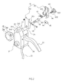
- the adjustable clamp 25 is screwed at the middle section via a pivot bolt 60; and a torsion spring 61 is assembled at the pivot bolt 60; at inner side of the exterior of internal and external plywood 251, 252, a corresponding arched flange 253 is arranged to form the clamping port 26, of which the interior of the internal plywood 251 is fastened onto the integrated control seat 20 via a bolt 62; the adjustable clamp 25 also comprises a packing locator 63; the packing locator 63 has a screw bolt 632 with rotary knob 631 so that a rotating cylinder 65 with tapped hole 64 is screwed onto the interior of the external plywood 252, and a long through-hole 66 is opened on the inner wall of the internal plywood 251; then, the screw bolt 632 is allowed to penetrate the long through-hole 66, and the tapped hole 64 of the rotating cylinder 65 is abutted into the trough 622 of the bolt head 621 at inner end of the internal plywood 251.
- a protruding seat 241 is formed on the assembly end 24 of the integrated control seat 20; the protruding seat 241 is defined to form an internal wall 242 and external wall 243; the protruding seat 241 is transversely provided with a through-hole 244, so that the inner wall of the internal plywood 251 of aforementioned adjustable clamp 25 is abutted onto the internal wall 242 of the protruding seat 241; the control member 28 is comprised of a rotary knob 282 with a threaded hole 281, and then the bolt 62 is used to penetrate the internal plywood 251 of the adjustable clamp 25, through-hole 244 of the protruding seat 241 and the threaded hole 281 of rotary knob 282, enabling the bolt head 621 of the bolt 62 to be abutted onto the internal plywood 251 of the adjustable clamp 25; the stud of the bolt 62 is screwed onto the threaded hole 281 of the rotary knob 28
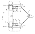
- the assembly end 41 of the assembly frame 40 could be embedded into the lateral guide inlet 52 of the connecting slot 51, then forcibly pushed forwards the single-sided oblique guide surface 581 to cross the retaining portion 58 of the pin 56; next, the assembly end 41 of the assembly frame 40 is limited securely between the internal retaining wall 53 of the connecting slot 51 and the retaining portion 58 of the pin 56; conversely, when the pin 56 is pulled upwards by the pulling portion 59, the retaining portion 58 is disengaged from the connecting slot 51, so the assembly end 41 of the assembly frame 40 could be released from the connecting slot 51.
- a reducing through-hole 551 is arranged at top of the groove 55 of the accommodating seat 54, so that the top of the pin 56 penetrates the reducing through-hole 551 to form the pulling portion 59; rings 70 are arranged on the pulling portion 59; then, the rings 70 at left and right sides of the pin 56 of the wheel body 13 of wheelchair body 10 are linked by a connector 71 (strip, rope, chain, rod) for simultaneous motion.
- a connector 71 strip, rope, chain, rod
- the second function of the integrated control seat 20 is to change the swinging angle of the integrated control seat 20 via the design of the swinging portion 63, so as to adjust the spacing between the acceleration lever 22 and handle 11 for manual operation; referring to FIG. 4 , the rotary knob 282 of the control member 28 could be rotated clockwise or counterclockwise to control the positioning or adjustment state of the integrated control seat 20; when the rotary knob 282 is loosened, the internal wall 242 of the protruding seat 241 and the internal plywood 251 of the adjustable clamp 25 will become loosened, so the swinging angle of the integrated control seat 20 can be adjusted; conversely, when the rotary knob 282 is tightened, the internal wall 242 of the protruding seat 241 and the internal plywood 251 of the adjustable clamp 25 will become tightened for positioning the integrated control seat 20.
- the integrated control seat 20 can be applied to wheelchair handles of different shapes.
- the adjustable clamp 25 of the integrated control seat 20 is adapted onto the cross-bar section of the handle 11; referring also to FIG. 5 , the adjustable clamp 25 of the integrated control seat 20 is adapted onto the curved section of the handle 11B.
- the assembly frame 40 is provided with adjustment member 42 that can define the protruding length of two assembly ends 41 in line with the extended width of the wheelchair body 10;
- the assembly end 41 of the assembly frame 40 when the assembly end 41 of the assembly frame 40 enters transversely into the lateral guide inlet 52 of the connecting slot 51, the assembly end 41 will slide along the single-sided oblique guide surface 581, so that the retaining portion 58 will push upwards the elastic member 57 and make it accumulate elastic force under the transverse force applied by the assembly end 41; as such, the assembly end 41 can smoothly slide into the connecting slot 51; when the assembly end 41 passes through the retaining portion 58, the elastic member 57 will release the elastic force, then the retaining portion 58 will slide down and protrude from the groove 55; the assembly end 41 is just positioned between the internal retaining wall 53 and retaining portion 58.
- the pulling portion 59 is fitted with a ring 70; and the rings 70 at left and right sides of the pin 56 of the wheel body 13 are linked by a connector 71 (strip, rope, chain, rod) for simultaneous motion.
- a connector 71 strip, rope, chain, rod
- the connector 71 could be pulled so that the pulling portion 59 at top of the pin 56 can protrude simultaneously from the reducing through-hole 551, allowing the retaining portion 58 to recess into the groove 55 and then disengage the assembly end 41 of the assembly frame 40.
Landscapes
- Health & Medical Sciences (AREA)
- Life Sciences & Earth Sciences (AREA)
- Animal Behavior & Ethology (AREA)
- General Health & Medical Sciences (AREA)
- Public Health (AREA)
- Veterinary Medicine (AREA)
- Chair Legs, Seat Parts, And Backrests (AREA)
- Motorcycle And Bicycle Frame (AREA)
- Handcart (AREA)
Priority Applications (3)
| Application Number | Priority Date | Filing Date | Title |
|---|---|---|---|
| AT08012317T ATE527974T1 (de) | 2008-07-08 | 2008-07-08 | Rollstuhlstruktur |
| ES08012317T ES2375297T3 (es) | 2008-07-08 | 2008-07-08 | Estructura de silla de ruedas. |
| EP08012317A EP2143407B1 (de) | 2008-07-08 | 2008-07-08 | Rollstuhlstruktur |
Applications Claiming Priority (1)
| Application Number | Priority Date | Filing Date | Title |
|---|---|---|---|
| EP08012317A EP2143407B1 (de) | 2008-07-08 | 2008-07-08 | Rollstuhlstruktur |
Publications (2)
| Publication Number | Publication Date |
|---|---|
| EP2143407A1 true EP2143407A1 (de) | 2010-01-13 |
| EP2143407B1 EP2143407B1 (de) | 2011-10-12 |
Family
ID=40120079
Family Applications (1)
| Application Number | Title | Priority Date | Filing Date |
|---|---|---|---|
| EP08012317A Active EP2143407B1 (de) | 2008-07-08 | 2008-07-08 | Rollstuhlstruktur |
Country Status (3)
| Country | Link |
|---|---|
| EP (1) | EP2143407B1 (de) |
| AT (1) | ATE527974T1 (de) |
| ES (1) | ES2375297T3 (de) |
Cited By (4)
| Publication number | Priority date | Publication date | Assignee | Title |
|---|---|---|---|---|
| GB2481404A (en) * | 2010-06-22 | 2011-12-28 | Wus Tech Co Ltd | Wheelchair with detachable drive means and frame |
| CN102349846A (zh) * | 2011-09-14 | 2012-02-15 | 迈柯唯医疗设备(苏州)有限公司 | 一种医用小车转动把手的角度锁紧调节机构及其应用公式 |
| WO2018054693A1 (de) * | 2016-09-23 | 2018-03-29 | Otto Bock Mobility Solution Gmbh | Chassis für eine mobilitätshilfe und für einen elektrorollstuhl |
| CN110143229A (zh) * | 2019-05-22 | 2019-08-20 | 济南正恒聚氨酯材料有限公司 | 一种保温板搬运装置 |
Citations (2)
| Publication number | Priority date | Publication date | Assignee | Title |
|---|---|---|---|---|
| GB2281727A (en) * | 1993-09-14 | 1995-03-15 | Fisher & Paykel | Wheelchair power system with quick-release drive units |
| DE20003481U1 (de) * | 1999-04-23 | 2000-06-21 | Rehatechnik Heymer GmbH, 59821 Arnsberg | Einrichtung zum lösbaren Befestigen einer Antriebseinheit an einem Rollstuhl |
-
2008
- 2008-07-08 ES ES08012317T patent/ES2375297T3/es active Active
- 2008-07-08 AT AT08012317T patent/ATE527974T1/de not_active IP Right Cessation
- 2008-07-08 EP EP08012317A patent/EP2143407B1/de active Active
Patent Citations (2)
| Publication number | Priority date | Publication date | Assignee | Title |
|---|---|---|---|---|
| GB2281727A (en) * | 1993-09-14 | 1995-03-15 | Fisher & Paykel | Wheelchair power system with quick-release drive units |
| DE20003481U1 (de) * | 1999-04-23 | 2000-06-21 | Rehatechnik Heymer GmbH, 59821 Arnsberg | Einrichtung zum lösbaren Befestigen einer Antriebseinheit an einem Rollstuhl |
Cited By (7)
| Publication number | Priority date | Publication date | Assignee | Title |
|---|---|---|---|---|
| GB2481404A (en) * | 2010-06-22 | 2011-12-28 | Wus Tech Co Ltd | Wheelchair with detachable drive means and frame |
| CN102349846A (zh) * | 2011-09-14 | 2012-02-15 | 迈柯唯医疗设备(苏州)有限公司 | 一种医用小车转动把手的角度锁紧调节机构及其应用公式 |
| CN102349846B (zh) * | 2011-09-14 | 2013-03-27 | 迈柯唯医疗设备(苏州)有限公司 | 一种医用小车转动把手的角度锁紧调节机构 |
| WO2018054693A1 (de) * | 2016-09-23 | 2018-03-29 | Otto Bock Mobility Solution Gmbh | Chassis für eine mobilitätshilfe und für einen elektrorollstuhl |
| US11000433B2 (en) | 2016-09-23 | 2021-05-11 | Otto Bock Mobility Solutions Gmbh | Chassis for a mobility aid and for an electric wheelchair |
| CN110143229A (zh) * | 2019-05-22 | 2019-08-20 | 济南正恒聚氨酯材料有限公司 | 一种保温板搬运装置 |
| CN110143229B (zh) * | 2019-05-22 | 2024-06-07 | 济南正恒聚氨酯材料有限公司 | 一种保温板搬运装置 |
Also Published As
| Publication number | Publication date |
|---|---|
| ATE527974T1 (de) | 2011-10-15 |
| EP2143407B1 (de) | 2011-10-12 |
| ES2375297T3 (es) | 2012-02-28 |
Similar Documents
| Publication | Publication Date | Title |
|---|---|---|
| US7886854B2 (en) | Wheelchair | |
| US8550437B2 (en) | Tool with working and positioning devices | |
| US7628052B2 (en) | Hand crimping tool interchangeable and interactive jaws | |
| US8307735B2 (en) | Bicycle stem | |
| EP2143407B1 (de) | Rollstuhlstruktur | |
| TWI515529B (zh) | 開關機構、具有開關機構之電子裝置及機殼的開蓋方法 | |
| US6698698B1 (en) | Telescopic tube | |
| EP1240982A3 (de) | Auslösevorrichtung mit Wahlfunktion | |
| EP1967324B8 (de) | Universeller Schließmechanismus für eine Klemme | |
| FI64067B (fi) | Verktyg foer aotdragning av spaennband | |
| US6755285B1 (en) | Wheeled walker brake lever mounting structure | |
| EP2070669A3 (de) | Elektrowerkzeug mit Grundplatteklemme | |
| US20100058914A1 (en) | Knife connector | |
| US20050217749A1 (en) | Cable tie tool having variable trigger linkage | |
| EP2336016A1 (de) | Manueller fahrzeugantrieb | |
| CN113948885A (zh) | 连接器装置 | |
| US7534946B1 (en) | Planetary string winder tool for musical instrument | |
| US6412372B1 (en) | Open-end wrench with resilient opening fun easy repositioning | |
| US6622587B1 (en) | Wheeled walker brake lever mounting arrangement | |
| CN115890554A (zh) | 链条快扣拆卸器 | |
| US6978704B2 (en) | Locking pliers | |
| EP1771325B8 (de) | Stelleinrichtung für eine feststellbremse | |
| US7188550B2 (en) | Open end adjustable spanner | |
| CN2608236Y (zh) | 手提电动工具的辅助把手装置 | |
| US20030066380A1 (en) | Adjustable steering assembly for an electric scooter |
Legal Events
| Date | Code | Title | Description |
|---|---|---|---|
| PUAI | Public reference made under article 153(3) epc to a published international application that has entered the european phase |
Free format text: ORIGINAL CODE: 0009012 |
|
| 17P | Request for examination filed |
Effective date: 20080811 |
|
| AK | Designated contracting states |
Kind code of ref document: A1 Designated state(s): AT BE BG CH CY CZ DE DK EE ES FI FR GB GR HR HU IE IS IT LI LT LU LV MC MT NL NO PL PT RO SE SI SK TR |
|
| AX | Request for extension of the european patent |
Extension state: AL BA MK RS |
|
| AKX | Designation fees paid |
Designated state(s): AT BE BG CH CY CZ DE DK EE ES FI FR GB GR HR HU IE IS IT LI LT LU LV MC MT NL NO PL PT RO SE SI SK TR |
|
| GRAP | Despatch of communication of intention to grant a patent |
Free format text: ORIGINAL CODE: EPIDOSNIGR1 |
|
| GRAS | Grant fee paid |
Free format text: ORIGINAL CODE: EPIDOSNIGR3 |
|
| GRAA | (expected) grant |
Free format text: ORIGINAL CODE: 0009210 |
|
| AK | Designated contracting states |
Kind code of ref document: B1 Designated state(s): AT BE BG CH CY CZ DE DK EE ES FI FR GB GR HR HU IE IS IT LI LT LU LV MC MT NL NO PL PT RO SE SI SK TR |
|
| REG | Reference to a national code |
Ref country code: GB Ref legal event code: FG4D |
|
| REG | Reference to a national code |
Ref country code: CH Ref legal event code: EP |
|
| REG | Reference to a national code |
Ref country code: IE Ref legal event code: FG4D |
|
| REG | Reference to a national code |
Ref country code: DE Ref legal event code: R096 Ref document number: 602008010312 Country of ref document: DE Effective date: 20111229 |
|
| REG | Reference to a national code |
Ref country code: NL Ref legal event code: VDEP Effective date: 20111012 |
|
| REG | Reference to a national code |
Ref country code: ES Ref legal event code: FG2A Ref document number: 2375297 Country of ref document: ES Kind code of ref document: T3 Effective date: 20120228 |
|
| LTIE | Lt: invalidation of european patent or patent extension |
Effective date: 20111012 |
|
| REG | Reference to a national code |
Ref country code: AT Ref legal event code: MK05 Ref document number: 527974 Country of ref document: AT Kind code of ref document: T Effective date: 20111012 |
|
| PG25 | Lapsed in a contracting state [announced via postgrant information from national office to epo] |
Ref country code: LT Free format text: LAPSE BECAUSE OF FAILURE TO SUBMIT A TRANSLATION OF THE DESCRIPTION OR TO PAY THE FEE WITHIN THE PRESCRIBED TIME-LIMIT Effective date: 20111012 Ref country code: NO Free format text: LAPSE BECAUSE OF FAILURE TO SUBMIT A TRANSLATION OF THE DESCRIPTION OR TO PAY THE FEE WITHIN THE PRESCRIBED TIME-LIMIT Effective date: 20120112 Ref country code: IS Free format text: LAPSE BECAUSE OF FAILURE TO SUBMIT A TRANSLATION OF THE DESCRIPTION OR TO PAY THE FEE WITHIN THE PRESCRIBED TIME-LIMIT Effective date: 20120212 |
|
| PG25 | Lapsed in a contracting state [announced via postgrant information from national office to epo] |
Ref country code: NL Free format text: LAPSE BECAUSE OF FAILURE TO SUBMIT A TRANSLATION OF THE DESCRIPTION OR TO PAY THE FEE WITHIN THE PRESCRIBED TIME-LIMIT Effective date: 20111012 Ref country code: HR Free format text: LAPSE BECAUSE OF FAILURE TO SUBMIT A TRANSLATION OF THE DESCRIPTION OR TO PAY THE FEE WITHIN THE PRESCRIBED TIME-LIMIT Effective date: 20111012 Ref country code: GR Free format text: LAPSE BECAUSE OF FAILURE TO SUBMIT A TRANSLATION OF THE DESCRIPTION OR TO PAY THE FEE WITHIN THE PRESCRIBED TIME-LIMIT Effective date: 20120113 Ref country code: PT Free format text: LAPSE BECAUSE OF FAILURE TO SUBMIT A TRANSLATION OF THE DESCRIPTION OR TO PAY THE FEE WITHIN THE PRESCRIBED TIME-LIMIT Effective date: 20120213 Ref country code: LV Free format text: LAPSE BECAUSE OF FAILURE TO SUBMIT A TRANSLATION OF THE DESCRIPTION OR TO PAY THE FEE WITHIN THE PRESCRIBED TIME-LIMIT Effective date: 20111012 Ref country code: SI Free format text: LAPSE BECAUSE OF FAILURE TO SUBMIT A TRANSLATION OF THE DESCRIPTION OR TO PAY THE FEE WITHIN THE PRESCRIBED TIME-LIMIT Effective date: 20111012 Ref country code: SE Free format text: LAPSE BECAUSE OF FAILURE TO SUBMIT A TRANSLATION OF THE DESCRIPTION OR TO PAY THE FEE WITHIN THE PRESCRIBED TIME-LIMIT Effective date: 20111012 |
|
| PG25 | Lapsed in a contracting state [announced via postgrant information from national office to epo] |
Ref country code: CY Free format text: LAPSE BECAUSE OF FAILURE TO SUBMIT A TRANSLATION OF THE DESCRIPTION OR TO PAY THE FEE WITHIN THE PRESCRIBED TIME-LIMIT Effective date: 20111012 |
|
| PG25 | Lapsed in a contracting state [announced via postgrant information from national office to epo] |
Ref country code: SK Free format text: LAPSE BECAUSE OF FAILURE TO SUBMIT A TRANSLATION OF THE DESCRIPTION OR TO PAY THE FEE WITHIN THE PRESCRIBED TIME-LIMIT Effective date: 20111012 Ref country code: CZ Free format text: LAPSE BECAUSE OF FAILURE TO SUBMIT A TRANSLATION OF THE DESCRIPTION OR TO PAY THE FEE WITHIN THE PRESCRIBED TIME-LIMIT Effective date: 20111012 Ref country code: DK Free format text: LAPSE BECAUSE OF FAILURE TO SUBMIT A TRANSLATION OF THE DESCRIPTION OR TO PAY THE FEE WITHIN THE PRESCRIBED TIME-LIMIT Effective date: 20111012 Ref country code: EE Free format text: LAPSE BECAUSE OF FAILURE TO SUBMIT A TRANSLATION OF THE DESCRIPTION OR TO PAY THE FEE WITHIN THE PRESCRIBED TIME-LIMIT Effective date: 20111012 Ref country code: BG Free format text: LAPSE BECAUSE OF FAILURE TO SUBMIT A TRANSLATION OF THE DESCRIPTION OR TO PAY THE FEE WITHIN THE PRESCRIBED TIME-LIMIT Effective date: 20120112 |
|
| PLBE | No opposition filed within time limit |
Free format text: ORIGINAL CODE: 0009261 |
|
| STAA | Information on the status of an ep patent application or granted ep patent |
Free format text: STATUS: NO OPPOSITION FILED WITHIN TIME LIMIT |
|
| PG25 | Lapsed in a contracting state [announced via postgrant information from national office to epo] |
Ref country code: PL Free format text: LAPSE BECAUSE OF FAILURE TO SUBMIT A TRANSLATION OF THE DESCRIPTION OR TO PAY THE FEE WITHIN THE PRESCRIBED TIME-LIMIT Effective date: 20111012 Ref country code: IT Free format text: LAPSE BECAUSE OF FAILURE TO SUBMIT A TRANSLATION OF THE DESCRIPTION OR TO PAY THE FEE WITHIN THE PRESCRIBED TIME-LIMIT Effective date: 20111012 Ref country code: RO Free format text: LAPSE BECAUSE OF FAILURE TO SUBMIT A TRANSLATION OF THE DESCRIPTION OR TO PAY THE FEE WITHIN THE PRESCRIBED TIME-LIMIT Effective date: 20111012 |
|
| 26N | No opposition filed |
Effective date: 20120713 |
|
| REG | Reference to a national code |
Ref country code: DE Ref legal event code: R097 Ref document number: 602008010312 Country of ref document: DE Effective date: 20120713 |
|
| PG25 | Lapsed in a contracting state [announced via postgrant information from national office to epo] |
Ref country code: AT Free format text: LAPSE BECAUSE OF FAILURE TO SUBMIT A TRANSLATION OF THE DESCRIPTION OR TO PAY THE FEE WITHIN THE PRESCRIBED TIME-LIMIT Effective date: 20111012 |
|
| PG25 | Lapsed in a contracting state [announced via postgrant information from national office to epo] |
Ref country code: MC Free format text: LAPSE BECAUSE OF NON-PAYMENT OF DUE FEES Effective date: 20120731 |
|
| REG | Reference to a national code |
Ref country code: CH Ref legal event code: PL |
|
| REG | Reference to a national code |
Ref country code: FR Ref legal event code: ST Effective date: 20130329 |
|
| PG25 | Lapsed in a contracting state [announced via postgrant information from national office to epo] |
Ref country code: CH Free format text: LAPSE BECAUSE OF NON-PAYMENT OF DUE FEES Effective date: 20120731 Ref country code: LI Free format text: LAPSE BECAUSE OF NON-PAYMENT OF DUE FEES Effective date: 20120731 Ref country code: FR Free format text: LAPSE BECAUSE OF NON-PAYMENT OF DUE FEES Effective date: 20120731 |
|
| REG | Reference to a national code |
Ref country code: IE Ref legal event code: MM4A |
|
| PG25 | Lapsed in a contracting state [announced via postgrant information from national office to epo] |
Ref country code: FI Free format text: LAPSE BECAUSE OF FAILURE TO SUBMIT A TRANSLATION OF THE DESCRIPTION OR TO PAY THE FEE WITHIN THE PRESCRIBED TIME-LIMIT Effective date: 20111012 |
|
| PG25 | Lapsed in a contracting state [announced via postgrant information from national office to epo] |
Ref country code: MT Free format text: LAPSE BECAUSE OF FAILURE TO SUBMIT A TRANSLATION OF THE DESCRIPTION OR TO PAY THE FEE WITHIN THE PRESCRIBED TIME-LIMIT Effective date: 20111012 Ref country code: IE Free format text: LAPSE BECAUSE OF NON-PAYMENT OF DUE FEES Effective date: 20120708 |
|
| PG25 | Lapsed in a contracting state [announced via postgrant information from national office to epo] |
Ref country code: TR Free format text: LAPSE BECAUSE OF FAILURE TO SUBMIT A TRANSLATION OF THE DESCRIPTION OR TO PAY THE FEE WITHIN THE PRESCRIBED TIME-LIMIT Effective date: 20111012 |
|
| PG25 | Lapsed in a contracting state [announced via postgrant information from national office to epo] |
Ref country code: LU Free format text: LAPSE BECAUSE OF NON-PAYMENT OF DUE FEES Effective date: 20120708 |
|
| PG25 | Lapsed in a contracting state [announced via postgrant information from national office to epo] |
Ref country code: HU Free format text: LAPSE BECAUSE OF FAILURE TO SUBMIT A TRANSLATION OF THE DESCRIPTION OR TO PAY THE FEE WITHIN THE PRESCRIBED TIME-LIMIT Effective date: 20080708 |
|
| PGFP | Annual fee paid to national office [announced via postgrant information from national office to epo] |
Ref country code: PT Payment date: 20190606 Year of fee payment: 16 |
|
| PGFP | Annual fee paid to national office [announced via postgrant information from national office to epo] |
Ref country code: DE Payment date: 20190926 Year of fee payment: 12 |
|
| REG | Reference to a national code |
Ref country code: DE Ref legal event code: R119 Ref document number: 602008010312 Country of ref document: DE |
|
| PG25 | Lapsed in a contracting state [announced via postgrant information from national office to epo] |
Ref country code: DE Free format text: LAPSE BECAUSE OF NON-PAYMENT OF DUE FEES Effective date: 20210202 |
|
| REG | Reference to a national code |
Ref country code: ES Ref legal event code: FD2A Effective date: 20211229 |
|
| PG25 | Lapsed in a contracting state [announced via postgrant information from national office to epo] |
Ref country code: ES Free format text: LAPSE BECAUSE OF NON-PAYMENT OF DUE FEES Effective date: 20200709 |
|
| PGFP | Annual fee paid to national office [announced via postgrant information from national office to epo] |
Ref country code: GB Payment date: 20250506 Year of fee payment: 18 |
|
| PGFP | Annual fee paid to national office [announced via postgrant information from national office to epo] |
Ref country code: BE Payment date: 20250728 Year of fee payment: 18 |