EP2143840A2 - Procédé et dispositif de fabrication d'une nappe de fils - Google Patents
Procédé et dispositif de fabrication d'une nappe de fils Download PDFInfo
- Publication number
- EP2143840A2 EP2143840A2 EP20090165030 EP09165030A EP2143840A2 EP 2143840 A2 EP2143840 A2 EP 2143840A2 EP 20090165030 EP20090165030 EP 20090165030 EP 09165030 A EP09165030 A EP 09165030A EP 2143840 A2 EP2143840 A2 EP 2143840A2
- Authority
- EP
- European Patent Office
- Prior art keywords
- threads
- fsn
- alignment
- winding surface
- individual
- Prior art date
- Legal status (The legal status is an assumption and is not a legal conclusion. Google has not performed a legal analysis and makes no representation as to the accuracy of the status listed.)
- Withdrawn
Links
- 238000000034 method Methods 0.000 title claims abstract description 28
- 239000000835 fiber Substances 0.000 title claims abstract description 9
- 238000004804 winding Methods 0.000 claims abstract description 86
- 238000012545 processing Methods 0.000 claims abstract description 11
- 238000004519 manufacturing process Methods 0.000 claims abstract description 10
- 239000004744 fabric Substances 0.000 claims description 27
- 239000000463 material Substances 0.000 claims description 16
- 239000000758 substrate Substances 0.000 claims description 12
- 238000006073 displacement reaction Methods 0.000 claims 1
- 235000014676 Phragmites communis Nutrition 0.000 abstract 1
- 238000003860 storage Methods 0.000 description 7
- 238000013461 design Methods 0.000 description 6
- 238000010586 diagram Methods 0.000 description 4
- 230000008859 change Effects 0.000 description 3
- 238000011161 development Methods 0.000 description 3
- 238000009434 installation Methods 0.000 description 3
- 230000035699 permeability Effects 0.000 description 3
- 230000008569 process Effects 0.000 description 3
- 239000004753 textile Substances 0.000 description 3
- 230000008901 benefit Effects 0.000 description 2
- 230000000295 complement effect Effects 0.000 description 2
- 230000003750 conditioning effect Effects 0.000 description 2
- 238000010276 construction Methods 0.000 description 2
- 241000792859 Enema Species 0.000 description 1
- 229920005830 Polyurethane Foam Polymers 0.000 description 1
- 230000015572 biosynthetic process Effects 0.000 description 1
- 238000009826 distribution Methods 0.000 description 1
- 238000001035 drying Methods 0.000 description 1
- 239000007920 enema Substances 0.000 description 1
- 229940095399 enema Drugs 0.000 description 1
- 238000005516 engineering process Methods 0.000 description 1
- 239000012530 fluid Substances 0.000 description 1
- 230000000704 physical effect Effects 0.000 description 1
- 239000011496 polyurethane foam Substances 0.000 description 1
- 238000012876 topography Methods 0.000 description 1
- 238000012549 training Methods 0.000 description 1
- 238000005406 washing Methods 0.000 description 1
Images


Classifications
-
- D—TEXTILES; PAPER
- D21—PAPER-MAKING; PRODUCTION OF CELLULOSE
- D21F—PAPER-MAKING MACHINES; METHODS OF PRODUCING PAPER THEREON
- D21F7/00—Other details of machines for making continuous webs of paper
- D21F7/08—Felts
- D21F7/083—Multi-layer felts
-
- D—TEXTILES; PAPER
- D21—PAPER-MAKING; PRODUCTION OF CELLULOSE
- D21F—PAPER-MAKING MACHINES; METHODS OF PRODUCING PAPER THEREON
- D21F1/00—Wet end of machines for making continuous webs of paper
- D21F1/0027—Screen-cloths
Definitions
- the invention relates to a method and apparatus for producing at least one scrim from at least one group of threads comprehensive layer of a covering for a web-making and / or web-processing machine, in which the individual threads of a unidirectionally oriented yarn sheet by means of parallel guides having alignment and Guiding device in their position aligned with each other wound on an endless rotating winding surface and fixed in position to each other.
- Textile fabrics for use as clothing for machines for producing fibrous webs are known in a large number of designs from the prior art. Depending on the field of application or application, these vary with regard to the construction and the execution. These are endlessly circulating belts which extend over the machine width and serve for the formation and guidance of a fibrous web through the machine for the production of these.
- a fundamental requirement for such clothing, in particular the wet part of a machine for producing a fibrous web, is to dehydrate the fibrous web as optimally as possible and to avoid rewetting in order to minimize the energy required for the subsequent drying on the wet part.
- the invention has for its object to develop a simple and inexpensive process for producing a fabric with individually required for the use of properties.
- a method for producing a, at least one Garngelege comprising at least one yarn sheet comprehensive layer of a fabric for a web-making and / or web-processing machine, wherein the individual threads of a unidirectionally oriented yarn sheet by means of parallel guides having alignment and guide means in their Position aligned with each other wound on an endless rotating winding surface and fixed in position to each other, according to the invention is characterized in that the adjustable winding width and / or thread density of the individual yarn sheet relative to the movable winding surface as a function of alignment of the alignment and guide device with respect to the longitudinal direction Changing surface is controllable.
- the inventive method allows by means of only one device configuration, the production of unidirectionally aligned yarn sheets of a fabric layer comprehensive layers by means of winding technology, the properties of individual yarn bundles are transverse to the longitudinal direction of a fabric produced in such a targeted manner to the application requirements adjustable via the alignment and guide device.
- the properties within a group of threads transversely to the longitudinal direction as well as the combination of these properties with one another in the width direction of the fabric can be influenced in a targeted manner via the production and storage of individual yarn bundles.
- the longitudinal direction of the clothing is understood to be the direction which coincides with the direction of circulation and thus the transport direction of the material web to be supported.
- the direction across this corresponds to the width direction.
- the alignment and guide device is characterized between the inlet of the individual threads in this and the respective outlet from this by guides. These are arranged parallel to each other to achieve a unidirectionally oriented yarn sheet. In the basic function state of the respective inlet, the guide and the outlet for a single thread are arranged parallel to the longitudinal axis of the winding surface.
- the inventors have recognized that the adjustable winding width and / or thread density can be adjusted as a function of a change in position of the alignment and guide device while maintaining the parallel alignment of the individual threads in this, in particular according to a first particularly advantageous embodiment by a pivoting movement of the alignment.
- the first embodiment has the advantage of a simple and very fast adjustability, wherein the pivot axis can be arranged outside of the alignment and guide means or within this.
- the second possibility of the superimposition of adjustment movements in differently aligned directions offers the advantage of a very accurate and sensitive adjustment.
- All adjusting movements is common that by the adjusting movement conditional inclined arrangement of the guides in the direction transverse to the longitudinal axis absolute distances between two mutually adjacent to the alignment and guide device arranged outlets for the individual threads due to the offset generated thereby in the longitudinal direction to each other, resulting in a constant number of threads and thread properties in a magnification the thread density is reflected in reducing the winding width.
- the absolute reduced distance that can be adjusted transversely to the longitudinal direction results as a function of the deflection angle and the actual distance between two adjacent outlets on the alignment and guide device.
- the adjustable winding width and / or thread density can be controlled as a function of a parallel adjustment movement of the individual guides within the alignment and guide device. This requires a correspondingly configured alignment and guidance device.
- the alignment and storage of the individual threads within a group of threads can be carried out with the same or different distance transversely to the longitudinal direction of the winding surface to each other, also within a group of yarns with different distances both symmetrically and asymmetrically with respect to a longitudinally aligned center axis of the yarn sheet.
- the alignment and guide device preferably has parallel and evenly spaced guides, which are preferably also arranged in one plane. Different symmetries within a group of threads are generated via the feed of the alignment and guide device with threads and thus the supply to the individual inlets on the alignment and guide device.
- winding width and the thread density can be adjusted via the alignment of the alignment and guide device
- further features of a yarn sheet can be used in a further development Longitudinal direction of the winding surface as a function of at least one
- the individual thread at least indirectly characterizing size can be adjusted. This applies in particular to the permeability generated by the thread scrim, the tightness of the yarn sheet, the topography and others.
- the individual threads of a group of threads can be selected and stored in such a way that the properties caused by the choice of the threads are kept constant within a group of threads transversely to the longitudinal direction of the winding surface or can be controlled in the transverse direction.
- At least one, preferably a plurality of thread coulters can be laid parallel to one another transversely to the longitudinal direction.
- the individual yarn bundles can be spaced apart from one another or else subsequently deposited in the transverse direction.
- the type of storage depends on the set cross-section of the fabric. Thus, it is conceivable to deposit the individual sets of threads individually or in groups symmetrically or asymmetrically with respect to each other. By analogy, these statements also apply to the storage in the height direction, i. perpendicular to the winding surface.
- at least one separating layer is preferably arranged between the individual yarn sheets, which is used simultaneously for fixing the individual yarn sheets and as a carrier for this.
- the winding surface can be formed by a substrate in the form of an endless circulating belt, wherein the substrate takes over either only a pure support function during winding and after completion of the winding process and the fixation, the thread assembly is subtracted from this, or at the same time serves as a carrier for supporting and embedding the yarn sheets.
- the first-mentioned embodiment is selected, since in this case the substrate is assigned to different functions during winding and then optimally.
- fixation of the individual threads of a group of threads takes place in this case directly to an already required for the winding component.
- the fixation can take place by means of a fleece layer covering the individual yarn sheet.
- the fixation is preferably carried out thermally, wherein the fixing layer contains melt fibers. This is characterized by a high strength and can be produced in a simple manner with little equipment.
- the fixation is mechanical.
- the layers which are produced according to the invention and which contain at least one group of threads can be completed with one or more layers as desired with one or more layers.
- the device for producing at least one Garngelege comprising at least one yarn sheet comprehensive layer of a covering for a web-making and / or web-processing machine, comprising a guide arrangement for supporting a forming an endless rotating winding surface substrate, a parallel guides having alignment and guide device, which is formed in a basic function position and arranged opposite the winding surface, that the guides are aligned parallel to the longitudinal direction of the winding surface is characterized in that the distance between the adjacent outlets of the alignment and Guide device preferably transversely, ie considered perpendicular to the longitudinal direction of the winding surface, is adjustable. This adjustability can be realized in a first particularly advantageous embodiment in that the alignment and guide device can be moved out of the basic function position.
- This movement can be done by pivoting about an aligned perpendicular to the winding surface pivot axis or a targeted adjustment of the alignment and guide direction on three axes.
- the structure of the alignment and guide device is kept relatively simple and the individual guides and the arrangement of the inlets and outlets and the guides connecting them within the alignment and guide device are invariable.
- the variation of the winding width via the adjustment of the distances of the outlets can be carried out, wherein the guides within the alignment and guide means, for example, are adjustable in parallel.
- the alignment and guide device can be stored stationary, but the adjustment is very complex.
- the alignment and guide direction and the winding surface are preferably displaceable relative to each other in the direction transverse to the longitudinal direction with repeated use of the same alignment and guide device.
- the individual thread groups are stored one after the other. It is also conceivable embodiment with a plurality of aligned transversely to the longitudinal direction of the winding surface alignment and guide means which are individually or in groups loadable and adjustable, wherein the entire width of the winding surface covering the scrim can be formed from the individual yarn bundles simultaneously.
- the alignment and guide device which is referred to as Riet or Webkamm, can be designed to be displaceable in particular in the production of fabrics in the longitudinal direction of the winding surface.
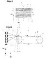
- FIG. 1 illustrates in a schematic simplified representation in a view from above of an execution of at least one scrim 3 comprehensive layer 2 of a fabric 4 for use in a web-making or web-processing machine.
- the FIG. 1 clarifies the orientation in installation position.
- the X-direction describes the longitudinal direction, which corresponds to the machine direction MD in the installed position in a web-producing or web-processing machine.
- the Y direction describes the width direction and thus the direction transverse to the machine direction CD.
- the Z direction corresponds to the height direction.
- the scrim 3 comprises at least one unidirectional arrangement of yarns F1 to Fn aligned in the longitudinal direction of the ply 2 and thus parallel to the longitudinal axis L2 of the ply 2.
- the individual yarns F1 to Fn are wound onto a movable endlessly rotating winding surface which is formed by a substrate 15 becomes.
- the substrate 15 is in the form of an endless belt forming a loop which, depending on the design, corresponds to a carrier 6 supporting the threads F1 to Fn and / or embedding it in itself or merely supporting the threads F1 to Fn during the winding process which are subsequently fixed in position relative to one another by means of a layer completely covering them, in particular a nonwoven layer.
- the individual threads F1 to Fn are designed in such a way and arranged in the width direction, ie transversely to the longitudinal direction of the fabric 4, that these regions form different properties, for example different fluid permeabilities. These properties are created by different thread densities and / or thread properties in these areas. These are in FIG. 1 the individual threads F1 to Fn are stored by way of example in bundles of threads FS1 to FS3.
- a thread family FS1 to FSn is understood to mean the unidirectional arrangement of a plurality of threads F1 to Fn.
- the individual yarn sheets FS1 and FS2 describe the arrangement of the yarns F in the lateral edge regions 16, 17 of the layer 2 of the fabric 4, while FS3 reproduces the arrangement of the yarns F in the middle region, ie transversely to the longitudinal direction between the edge regions 16, 17.
- the yarn sheets FS1 and FS2 are characterized by a larger thread density than the yarn sheet FS3 in the middle region. This is realized, for example, by a different number of threads F1 to Fn of the same thread design over a length unit and / or the arrangement of threads of different thread properties, such as geometry, dimensioning, material. In order to be able to produce regions of different properties, in particular with threads of the same design, they are varied in their density in a unidirectional arrangement.
- the single ones Threads of a group of yarns FS1 to FS3 are each aligned in the same direction and run substantially parallel to one another.
- the different yarn bundles FS1 to FS3 can be produced in a simple manner by means of a method according to the invention and a device 1 according to the invention for winding yarn arrangements on a rotating winding surface 13.
- FIG. 2 Such a device 1 is exemplary in FIG FIG. 2 shown.
- the movable winding surface 13 is formed by the outer periphery 18 of an endless belt, ie a loop, of a substrate 15, which at the same time serves as carrier 6 the layer 2 can act for the scrim 3.
- the substrate 15 is guided over the guide arrangement 9, comprising at least two deflecting rollers 19, 20, of which at least one is drivable and which can be fixed in position relative to one another or else adjustable in dependence on the circumferential length of the substrate 15.
- the scrim 3 of the layer 2 is generated by the arrangement of the individual threads F1 to Fn within the yarn sheets FS1 to FSn, which are provided via the device 5.
- the device 5 is exemplified as a creel 7, comprising a plurality of coils 7.1 to 7.n, which are arranged offset to one another in the horizontal and / or vertical direction and provide the individual threads F1 to Fn.
- the individual threads F1 to Fn which are to be understood as elongated flexible structures which may be of different designs, are aligned and adjusted via an alignment and guide device 8 for adjusting the distances between the individual threads provided via the coils 7.1 to 7.n F1 to Fn led.
- This alignment and guide device 8 is also referred to as Riet and is in front of the storage location of the threads F1 to Fn the movable winding surface 13 is arranged.
- the individual threads F1 to Fn of the thread arrangement of a yarn layer 3 are positioned in their position to each other with adjustment of the distances from each other.
- the alignment takes place in the longitudinal direction and the position assignment in the transverse direction spaced from one another, wherein over these distances in the transverse direction, the thread density is adjustable.
- FIG. 2 also indicated a coordinate system that of the yarn layer 3 and thus the position 2 in FIG. 1 equivalent.
- the X-direction illustrates the longitudinal direction of the finished fabric 4, the Y-direction the transverse direction and thus the width direction of the fabric in installation position.
- the Z direction illustrates the height direction.
- the aligning and guiding device 8 for aligning and adjusting the thread density is characterized in that it contains guide grooves 10 in which the individual threads F1 to Fn, which are provided via the spools 7.1 to 7.n, are in position relative to each other in the transverse direction, ie, width direction, the covering 4 viewed in the installation position spaced apart from each other.
- the arrangement of the individual threads F1 to Fn a yarn sheet FS1 to FSn takes place in parallel.
- the guide grooves 10 are also aligned parallel to each other and in the basic position of the alignment and guide device 8, which corresponds to the functional position maximum winding width, spaced over the entire width to each other.
- the device 8 In order to influence the width, in particular winding width of a group of yarns FS1 to FSn or subsets of a group of yarns, and thus the arrangement of the individual spaced apart in the transverse direction threads F1 to Fn, it is inventively provided to perform the device 8 adjustable.
- the adjustability takes place in such a way that the device 8 for aligning and adjusting the thread density is suitable for providing a thread arrangement of unchanged number of threads, which leads to a change in the resulting winding width.
- the alignment and guide device 8 for adjusting the thread density is included for the individual threads F1 to Fn characterized by an inlet 11 and an outlet 12, which are each connected to each other via a groove 10.
- the alignment and guide device 8 is oriented transversely to the longitudinal direction of the winding surface 13, i. Inlet and outlet 11, 12 are viewed in the longitudinal direction of the fabric 4 consecutively and arranged parallel to each other.
- the connecting grooves 10 extend parallel to the longitudinal direction of the winding surface 13.
- This adjustment is possible in the simplest case by a simple pivot bearing 21, wherein the pivot axis S21 is arranged perpendicular to a plane spanned by the X, Y direction plane.
- the alignment and guide device 8, which applies the individual threads F1 to Fn in the longitudinal direction, is thereby rotated about the pivot axis S21.
- This rotatability can also be generated by a superimposed adjusting movement of the alignment and guide device 8 in at least two directions.
- the winding width of a group of threads from the individual threads F1 to Fn, which are provided via the coils 7.1 to 7.n can be varied almost as desired and thus also the thread density per unit length in the direction transverse to the longitudinal axis of the winding surface 13th
- the alignment and guide device 8 may extend over the entire width of the winding surface 13 or preferably only a portion of this. In order to cover the entire width of a winding surface 13, preferably the device 8 is slidably arranged and supported in the width direction.
- FIGS. 3a and 3b illustrate contrasting each other in the individual functional positions of the alignment and guide device 8 resulting storage images for the individual threads F1 to Fn a yarn sheet FS1 in the form of at least one component of a yarn layer 3.
- Die FIG. 3a illustrates the basic functional condition I of the alignment and guide device 8, which runs exactly perpendicular to the longitudinal direction of the winding surface 13 under parallel arrangement of inlet 11 and outlet 12 and guide grooves 10 in the longitudinal direction.
- the resulting maximum winding width is designated h1.
- FIG. 3b an embodiment after adjustment of the alignment and guide device 8 about the pivot axis S21 at an angle to the transverse direction.
- the resulting winding width hs2 of the yarn sheet FS1 changes here while the number of yarns remains the same.
- the changed resulting winding width is designated h2.
- the thread density is increased.
- This functional state is denoted by 11.
- FIG. 4 illustrates exemplarily a layer 2 with a scrim 3 of yarn sheets FS1 to FS4, in which the distances of the individual threads F1 to Fn over the entire width, which corresponds to the winding width h2, vary by at least 10%.
- threads F1 to F7 of the first group of threads FS1 which are arranged spaced apart in the transverse direction, ie, perpendicular to the longitudinal direction, at a distance a 1 , wherein the arrangement is parallel, while for the illustrated threads F8 to F9 of the second adjacent arranged yarn bundle FS2 each have a distance a 2 is provided and further in the transverse direction of this area further threads F10 to F12 of the yarn sheet FS3 and F13 to F14 of the yarn sheet FS4 connect, which are spaced from each other at different distances.
- the dependency of the winding density on the pressure curve is reproduced in a schematic diagram in a simplified diagram below. In the diagram, the winding density is plotted over the transverse direction and the pressure curve p.
- a multiplicity of different designs of yarn layers 3 for use in clothing 4 for machines for producing and / or processing webs of material can furthermore be produced.
- a longitudinally preferably parallel thread arrangement can be arranged one above the other in one or more layers.
- a separating layer is arranged between the individual yarn layers 3.1 to 3.n. This is designated 14.
- FIG. 5a illustrates an example of a sectional view in the XZ plane of an embodiment of a fabric 4 with several superimposed layers 2.1 to 2.n with an inventive arrangement of the individual threads in the form of Fadengelegen 3.1 to 3.n.
- a first layer 2.1 containing the carrier 6 is exemplarily provided with a thread covering 3.1, over which a separating layer 14 is arranged, and on which further a further layer 2.2 is provided which contains a thread layer 3.2, which in its thread density opposite the situation 2.1 varies.
- the layer 2.2 forms, for example, the surface contacting the material web.
- the winding device 1 is controlled and operated so that different storage images can be generated.
- FIG. 5b illustrated by means of an axial section in the YZ plane in a schematically greatly simplified representation based on an embodiment of the layer 2.1, the arrangement of the yarn layer 3 with Longitudinal threads and with the longitudinal threads crossing transverse threads FQ, with only a transverse thread FQ is visible.
- at least a selection of threads F1 to F6 of the layer 2.1 are placed at different distances both symmetrically and asymmetrically to each other, wherein the distance b 1 to b 3 of two adjacent threads F1 to F6 preferably changes in the course of their yarn layer 3.1. The change can take place continuously, abruptly, periodically, regionally or the like.
- the threads F1 to F6 of the layer 2.1 are laid symmetrically or asymmetrically in several groups with each other, wherein the groups of threads of the layer 2.1 in turn are symmetrical or asymmetrical to each other.
- the different distances b1 to b5 are selected according to a pattern, but may also be selected randomly or in combination.
- the longitudinal threads of the layer 2.1 and the transverse threads FQ extend at least in regions at an angle to each other, which is in the range of ⁇ 0 and ⁇ 90 °.
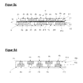
- FIG. 5c illustrates the FIG. 5c an execution with two a Garngelege 3.1, 3.2 forming adjacent thread arrangements of threads F1 to F5 and F6 to F10 with at least partially the same or approximately the same orientation and at least partially at least one different property, a complementary pairwise positioning of threads F1 to F5 and F6 to F10 to each other.
- the different property consists in the illustrated embodiment in the dimensioning of the individual threads F1 to F10. In the further embodiment, however, it may also be the thread hardness, the thread structure and the thread material or the like used.
- the permeable material comprises at least a polyurethane foam.
- a preferably full-surface permeable layer is introduced in the form of a release liner 14, and the two adjacent layers of threads at least partially under an angle which is in a range of ⁇ 0 to ⁇ 90 °.
- the angle has a value in the range of 0 °, ie, the individual layers 2.1 and 2.2 of threads F1 to F5 and F6 to F10 have an approximately same orientation.
- the scrim 3.2 of the layer 2.2 is applied to the carrier 6.
- FIG. 5d illustrates a further embodiment of a fabric 4.
- this two yarn sheets FS1 and FS2 of threads F1 to F5 and F6 to F10 are provided, which are characterized by at least partially the same or approximately the same orientation and at least partially executed at least one different property, the have a complementary pairwise positioning of threads to each other.
- the threads F1 to F5 of the thread group FS1 have the at least one different property alternately and offset from the threads F6 to F10 of the adjacent thread group FS2.
- the different property is the thread thickness in the illustrated embodiment. However, in a further embodiment, it may also be the thread hardness, the thread structure, the thread material or the like.
- the threads F1, F3, F5 of the yarn sheet FS1 of the layer 2 are characterized by a smaller thread thickness than the adjacent threads F2, F4 of the yarn sheet FS1 and F6, F8, F10 of the yarn sheet FS2.
- the adjacent threads F1 to F5 and F6 to F10 each of the same thread group FS1 and FS2 again have a contrary thread thickness. These geometries are repeated, so that in the final result a uniform thickness of the entire yarn layer 3 is given.
- the same thread thickness can also extend over several threads of the same group of threads and / or with a pattern in the same layer.
- the two adjacent yarn bundles FS1 and FS2 of yarns F1 to F5 and F6 to F10 extend at least in regions at an angle which assumes a value in the range of ⁇ 0 and ⁇ 90 °. In the illustrated embodiment, the angle is formed in the range of 0 °.
- the thread ply shown may be part of a middle layer of a press felt which has a fine nonwoven layer to the material web and a coarse nonwoven layer on the support side.
- guide assembly 10 guide 11 enema 12 outlet 13 winding surface 14 pivot bearing 15 substratum 16 border area 17 border area 18 separating layer 19 idler pulley 20 idler pulley 21 pivot bearing MD machine direction CD Direction transverse to the machine direction a1, a2 distance b1-b5 distance h1, h2 winding width F1 -Fn threads FS1-FS n yarn sheet Z1 - Zn interspaces S21 swivel axis I, II functional status
Landscapes
- Nonwoven Fabrics (AREA)
Applications Claiming Priority (1)
| Application Number | Priority Date | Filing Date | Title |
|---|---|---|---|
| DE200810040282 DE102008040282A1 (de) | 2008-07-09 | 2008-07-09 | Verfahren und Vorrichtung zur Herstellung eines Fadengeleges |
Publications (1)
| Publication Number | Publication Date |
|---|---|
| EP2143840A2 true EP2143840A2 (fr) | 2010-01-13 |
Family
ID=41134551
Family Applications (1)
| Application Number | Title | Priority Date | Filing Date |
|---|---|---|---|
| EP20090165030 Withdrawn EP2143840A2 (fr) | 2008-07-09 | 2009-07-09 | Procédé et dispositif de fabrication d'une nappe de fils |
Country Status (3)
| Country | Link |
|---|---|
| EP (1) | EP2143840A2 (fr) |
| CN (1) | CN201648701U (fr) |
| DE (1) | DE102008040282A1 (fr) |
Cited By (3)
| Publication number | Priority date | Publication date | Assignee | Title |
|---|---|---|---|---|
| WO2012016875A1 (fr) * | 2010-07-26 | 2012-02-09 | Voith Patent Gmbh | Tamis de formage et procédé de fabrication d'un tel tamis |
| CN106245402A (zh) * | 2016-09-19 | 2016-12-21 | 杭州诺邦无纺股份有限公司 | 湿法水刺专用锥形涡轮分散器及分散纤维团的方法 |
| CN112647196A (zh) * | 2020-12-29 | 2021-04-13 | 李启虎 | 一种纤维纺织机及纺织工艺 |
Families Citing this family (4)
| Publication number | Priority date | Publication date | Assignee | Title |
|---|---|---|---|---|
| DE102011117324A1 (de) | 2011-10-28 | 2013-05-02 | Wolfgang Hoeck | Führungsvorrichtung zum Führen einer Mehrzahl von Fasern sowie Vorrichtung zur Herstellung eines Faserverbundbauteils |
| DE102012020624A1 (de) * | 2012-10-19 | 2014-04-24 | Wolfgang Hoeck | Führungsvorrichtung zum Führen einer Mehrzahl von Fäden zur Herstellung eines Faserverbundbauteils |
| DE102014207017A1 (de) * | 2014-04-11 | 2015-10-15 | Bayerische Motoren Werke Aktiengesellschaft | Verfahren zur Herstellung eines Fahrzeug-Halbzeugs sowie Faser-Halbzeug und Bauteil aus einem Faserverbundwerkstoff |
| CN111074210A (zh) * | 2018-10-18 | 2020-04-28 | 大永真空科技股份有限公司 | 适用于纱线镀膜的腔体 |
Citations (1)
| Publication number | Priority date | Publication date | Assignee | Title |
|---|---|---|---|---|
| US20030192665A1 (en) | 2000-12-18 | 2003-10-16 | Tamfelt Oyj Abp | Method of making press felt, and press felt |
Family Cites Families (1)
| Publication number | Priority date | Publication date | Assignee | Title |
|---|---|---|---|---|
| DE102005030773A1 (de) | 2005-07-01 | 2007-01-11 | Voith Patent Gmbh | Papiermaschinenbespannung |
-
2008
- 2008-07-09 DE DE200810040282 patent/DE102008040282A1/de not_active Withdrawn
-
2009
- 2009-07-09 EP EP20090165030 patent/EP2143840A2/fr not_active Withdrawn
- 2009-07-09 CN CN 200920178013 patent/CN201648701U/zh not_active Expired - Fee Related
Patent Citations (1)
| Publication number | Priority date | Publication date | Assignee | Title |
|---|---|---|---|---|
| US20030192665A1 (en) | 2000-12-18 | 2003-10-16 | Tamfelt Oyj Abp | Method of making press felt, and press felt |
Cited By (3)
| Publication number | Priority date | Publication date | Assignee | Title |
|---|---|---|---|---|
| WO2012016875A1 (fr) * | 2010-07-26 | 2012-02-09 | Voith Patent Gmbh | Tamis de formage et procédé de fabrication d'un tel tamis |
| CN106245402A (zh) * | 2016-09-19 | 2016-12-21 | 杭州诺邦无纺股份有限公司 | 湿法水刺专用锥形涡轮分散器及分散纤维团的方法 |
| CN112647196A (zh) * | 2020-12-29 | 2021-04-13 | 李启虎 | 一种纤维纺织机及纺织工艺 |
Also Published As
| Publication number | Publication date |
|---|---|
| CN201648701U (zh) | 2010-11-24 |
| DE102008040282A1 (de) | 2010-01-14 |
Similar Documents
| Publication | Publication Date | Title |
|---|---|---|
| DE69814009T2 (de) | Harzimprägniertes Band zur Anwendung in Papiermaschinen und dergleichen industriellen Anwendungen | |
| DE2639466B2 (de) | Verfahren und Vorrichtung zur Herstellung eines nichtgewebten Textilmaterials | |
| DE102008040282A1 (de) | Verfahren und Vorrichtung zur Herstellung eines Fadengeleges | |
| WO2009156385A2 (fr) | Procédé de réalisation d'une structure de fils multiaxiale, couches fibreuses unidirectionnelles et leur procédé de réalisation, structure de fils multiaxiale et pièce composite comprenant une matrice | |
| EP0544167B1 (fr) | Toile pour machine à papier, en particulier toile de séchage | |
| DE69727706T2 (de) | Geflochtenes grundgewebe für eines schuhpressband | |
| DE69627234T2 (de) | Pressgewebe | |
| WO2009077216A1 (fr) | Bande transporteuse et son procédé de fabrication | |
| WO2017046128A1 (fr) | Chemise de presse et procédé de fabrication associé | |
| EP2984224B1 (fr) | Procédé de production d'une toile industrielle | |
| DE102007038931B4 (de) | Fadenlagennähwirkstoffe | |
| DE102014118217B4 (de) | Rundstrickmaschine | |
| DE102015005160B4 (de) | Verfahren und Vorrichtung zum Herstellen von Fadengelegen | |
| EP2236666A1 (fr) | Feutre de presse ayant une zone de jonction et étant doté d'une structure de support non tissée fabriquée à plat | |
| DE102007000579A1 (de) | Papiermaschinenbespannungen, insbesondere für Pressfilze, und Verfahren zu deren Herstellung | |
| DE102018120558A1 (de) | Verfahren zur Bearbeitung eines Pressmantels | |
| DE102018120559A1 (de) | Verfahren zur Bearbeitung eines Walzenbezugs | |
| EP4261345A1 (fr) | Bande transporteuse, en particulier bande de transfert pour machine à papier | |
| DE102004052414B3 (de) | Verfahren zum Herstellen einer eine biaxiale Gitterstruktur aufweisenden Kettenwirkware mit großen Gitteröffnungen | |
| EP2017206B1 (fr) | Dispositif pour la fabrication d' un voile non-tissé spunbond | |
| DE102007024507A1 (de) | Papiermaschinenbespannung | |
| DE102016113721A1 (de) | Faserflor-basiertes bahnförmiges Textil mit unidirektional erhöhter Festigkeit | |
| DE102008001064A1 (de) | Bespannung und Verfahren zu deren Herstellung | |
| EP1925726B1 (fr) | Bande de couture pour une machine destinée à la fabrication de matériau en bande, en particulier du papier ou du carton | |
| EP2806058B1 (fr) | Thermofixation intégrée |
Legal Events
| Date | Code | Title | Description |
|---|---|---|---|
| PUAI | Public reference made under article 153(3) epc to a published international application that has entered the european phase |
Free format text: ORIGINAL CODE: 0009012 |
|
| AK | Designated contracting states |
Kind code of ref document: A2 Designated state(s): AT BE BG CH CY CZ DE DK EE ES FI FR GB GR HR HU IE IS IT LI LT LU LV MC MK MT NL NO PL PT RO SE SI SK SM TR |
|
| RTI1 | Title (correction) |
Free format text: METHOD AND DEVICE FOR PRODUCING A LAYER OF YARNS |
|
| STAA | Information on the status of an ep patent application or granted ep patent |
Free format text: STATUS: THE APPLICATION IS DEEMED TO BE WITHDRAWN |
|
| 18D | Application deemed to be withdrawn |
Effective date: 20130201 |