EP2143997B1 - Kessel zum verbrennen von feinem kohlenstaub - Google Patents
Kessel zum verbrennen von feinem kohlenstaub Download PDFInfo
- Publication number
- EP2143997B1 EP2143997B1 EP08740281.4A EP08740281A EP2143997B1 EP 2143997 B1 EP2143997 B1 EP 2143997B1 EP 08740281 A EP08740281 A EP 08740281A EP 2143997 B1 EP2143997 B1 EP 2143997B1
- Authority
- EP
- European Patent Office
- Prior art keywords
- pulverized coal
- combustion air
- amount
- coal
- burners
- Prior art date
- Legal status (The legal status is an assumption and is not a legal conclusion. Google has not performed a legal analysis and makes no representation as to the accuracy of the status listed.)
- Active
Links
- 239000003245 coal Substances 0.000 title claims description 264
- 238000002485 combustion reaction Methods 0.000 claims description 89
- 230000001603 reducing effect Effects 0.000 claims description 25
- 238000003801 milling Methods 0.000 claims description 13
- 239000007789 gas Substances 0.000 claims description 8
- 239000012530 fluid Substances 0.000 claims description 5
- QVGXLLKOCUKJST-UHFFFAOYSA-N atomic oxygen Chemical compound [O] QVGXLLKOCUKJST-UHFFFAOYSA-N 0.000 claims description 4
- 238000001514 detection method Methods 0.000 claims description 4
- 239000001301 oxygen Substances 0.000 claims description 4
- 229910052760 oxygen Inorganic materials 0.000 claims description 4
- 238000003303 reheating Methods 0.000 claims 3
- 238000011144 upstream manufacturing Methods 0.000 claims 2
- 239000000446 fuel Substances 0.000 description 5
- 238000004364 calculation method Methods 0.000 description 4
- 238000002474 experimental method Methods 0.000 description 4
- 238000004519 manufacturing process Methods 0.000 description 4
- 238000012937 correction Methods 0.000 description 3
- 230000000694 effects Effects 0.000 description 3
- 238000000034 method Methods 0.000 description 3
- 239000002802 bituminous coal Substances 0.000 description 2
- 238000010586 diagram Methods 0.000 description 2
- 239000003476 subbituminous coal Substances 0.000 description 2
- 238000009838 combustion analysis Methods 0.000 description 1
- 239000000567 combustion gas Substances 0.000 description 1
- 230000007423 decrease Effects 0.000 description 1
- 230000003247 decreasing effect Effects 0.000 description 1
- 238000013461 design Methods 0.000 description 1
- 239000000428 dust Substances 0.000 description 1
- 238000010248 power generation Methods 0.000 description 1
- 238000012545 processing Methods 0.000 description 1
Images



Classifications
-
- G—PHYSICS
- G01—MEASURING; TESTING
- G01F—MEASURING VOLUME, VOLUME FLOW, MASS FLOW OR LIQUID LEVEL; METERING BY VOLUME
- G01F1/00—Measuring the volume flow or mass flow of fluid or fluent solid material wherein the fluid passes through a meter in a continuous flow
- G01F1/74—Devices for measuring flow of a fluid or flow of a fluent solid material in suspension in another fluid
-
- F—MECHANICAL ENGINEERING; LIGHTING; HEATING; WEAPONS; BLASTING
- F23—COMBUSTION APPARATUS; COMBUSTION PROCESSES
- F23C—METHODS OR APPARATUS FOR COMBUSTION USING FLUID FUEL OR SOLID FUEL SUSPENDED IN A CARRIER GAS OR AIR
- F23C99/00—Subject-matter not provided for in other groups of this subclass
-
- F—MECHANICAL ENGINEERING; LIGHTING; HEATING; WEAPONS; BLASTING
- F22—STEAM GENERATION
- F22B—METHODS OF STEAM GENERATION; STEAM BOILERS
- F22B35/00—Control systems for steam boilers
-
- F—MECHANICAL ENGINEERING; LIGHTING; HEATING; WEAPONS; BLASTING
- F22—STEAM GENERATION
- F22G—SUPERHEATING OF STEAM
- F22G5/00—Controlling superheat temperature
-
- F—MECHANICAL ENGINEERING; LIGHTING; HEATING; WEAPONS; BLASTING
- F23—COMBUSTION APPARATUS; COMBUSTION PROCESSES
- F23D—BURNERS
- F23D1/00—Burners for combustion of pulverulent fuel
-
- F—MECHANICAL ENGINEERING; LIGHTING; HEATING; WEAPONS; BLASTING
- F23—COMBUSTION APPARATUS; COMBUSTION PROCESSES
- F23K—FEEDING FUEL TO COMBUSTION APPARATUS
- F23K3/00—Feeding or distributing of lump or pulverulent fuel to combustion apparatus
- F23K3/02—Pneumatic feeding arrangements, i.e. by air blast
-
- F—MECHANICAL ENGINEERING; LIGHTING; HEATING; WEAPONS; BLASTING
- F23—COMBUSTION APPARATUS; COMBUSTION PROCESSES
- F23N—REGULATING OR CONTROLLING COMBUSTION
- F23N1/00—Regulating fuel supply
- F23N1/02—Regulating fuel supply conjointly with air supply
- F23N1/022—Regulating fuel supply conjointly with air supply using electronic means
-
- G—PHYSICS
- G01—MEASURING; TESTING
- G01F—MEASURING VOLUME, VOLUME FLOW, MASS FLOW OR LIQUID LEVEL; METERING BY VOLUME
- G01F1/00—Measuring the volume flow or mass flow of fluid or fluent solid material wherein the fluid passes through a meter in a continuous flow
- G01F1/66—Measuring the volume flow or mass flow of fluid or fluent solid material wherein the fluid passes through a meter in a continuous flow by measuring frequency, phase shift or propagation time of electromagnetic or other waves, e.g. using ultrasonic flowmeters
- G01F1/666—Measuring the volume flow or mass flow of fluid or fluent solid material wherein the fluid passes through a meter in a continuous flow by measuring frequency, phase shift or propagation time of electromagnetic or other waves, e.g. using ultrasonic flowmeters by detecting noise and sounds generated by the flowing fluid
-
- G—PHYSICS
- G01—MEASURING; TESTING
- G01F—MEASURING VOLUME, VOLUME FLOW, MASS FLOW OR LIQUID LEVEL; METERING BY VOLUME
- G01F1/00—Measuring the volume flow or mass flow of fluid or fluent solid material wherein the fluid passes through a meter in a continuous flow
- G01F1/704—Measuring the volume flow or mass flow of fluid or fluent solid material wherein the fluid passes through a meter in a continuous flow using marked regions or existing inhomogeneities within the fluid stream, e.g. statistically occurring variations in a fluid parameter
- G01F1/7046—Measuring the volume flow or mass flow of fluid or fluent solid material wherein the fluid passes through a meter in a continuous flow using marked regions or existing inhomogeneities within the fluid stream, e.g. statistically occurring variations in a fluid parameter using electrical loaded particles as tracer, e.g. ions or electrons
-
- G—PHYSICS
- G01—MEASURING; TESTING
- G01F—MEASURING VOLUME, VOLUME FLOW, MASS FLOW OR LIQUID LEVEL; METERING BY VOLUME
- G01F1/00—Measuring the volume flow or mass flow of fluid or fluent solid material wherein the fluid passes through a meter in a continuous flow
- G01F1/704—Measuring the volume flow or mass flow of fluid or fluent solid material wherein the fluid passes through a meter in a continuous flow using marked regions or existing inhomogeneities within the fluid stream, e.g. statistically occurring variations in a fluid parameter
- G01F1/708—Measuring the time taken to traverse a fixed distance
- G01F1/712—Measuring the time taken to traverse a fixed distance using auto-correlation or cross-correlation detection means
-
- G—PHYSICS
- G01—MEASURING; TESTING
- G01P—MEASURING LINEAR OR ANGULAR SPEED, ACCELERATION, DECELERATION, OR SHOCK; INDICATING PRESENCE, ABSENCE, OR DIRECTION, OF MOVEMENT
- G01P5/00—Measuring speed of fluids, e.g. of air stream; Measuring speed of bodies relative to fluids, e.g. of ship, of aircraft
- G01P5/18—Measuring speed of fluids, e.g. of air stream; Measuring speed of bodies relative to fluids, e.g. of ship, of aircraft by measuring the time taken to traverse a fixed distance
- G01P5/22—Measuring speed of fluids, e.g. of air stream; Measuring speed of bodies relative to fluids, e.g. of ship, of aircraft by measuring the time taken to traverse a fixed distance using auto-correlation or cross-correlation detection means
-
- F—MECHANICAL ENGINEERING; LIGHTING; HEATING; WEAPONS; BLASTING
- F23—COMBUSTION APPARATUS; COMBUSTION PROCESSES
- F23N—REGULATING OR CONTROLLING COMBUSTION
- F23N2239/00—Fuels
- F23N2239/02—Solid fuels
-
- F—MECHANICAL ENGINEERING; LIGHTING; HEATING; WEAPONS; BLASTING
- F23—COMBUSTION APPARATUS; COMBUSTION PROCESSES
- F23N—REGULATING OR CONTROLLING COMBUSTION
- F23N2241/00—Applications
- F23N2241/10—Generating vapour
Definitions
- the present invention relates to a pulverized coal burning boiler such as a power generation boiler apparatus and particularly to a pulverized coal burning boiler in which a plurality of coal feeding pipes are connected to a single milling means such as a roller mill so that pulverized coal generated by the milling means is distributed to the plurality of coal feeding pipes, fed to individual pulverized coal burners and burned.
- a pulverized coal burning boiler uses a two-stage burning method in which air with a smaller ratio than a theoretical air ratio is imported by a burner and low NOx combustion is performed in a reducing atmosphere in order to reduce the amount of emergence of NOx and then additional air is imported from an after air port (hereinafter abbreviated as AAP) as a post-stage in order to burn unburned contents such as CO.
- AAP after air port
- the amount of air imported into a combustion device as a whole is imported so excessively as to be about 1.2 which is more than the theoretical air ratio of 1.0.
- Patent Documents JP-A-8-270931 , US6037783A and US6656026B1 can be listed.
- a pulverized coal burning method for reducing the amount of produced NOx has been disclosed in JP-A-8-270931 .
- combustion of pulverized coal by an in-flame denitration type pulverized coal burner which forms a reducing flame region short of oxygen takes a point of view that the concentration of NOx in exhaust gas is largely affected by the temperature of the reducing flame region or the air ratio of the reducing flame region.
- Configuration is made so that a light extractor is attached to the pulverized coal burner, light of flame in the reducing flame region formed by the burner is detected by the light extractor, the detection signal is led to an emission spectrometer, the intensity of emitted light is detected, the temperature of the reducing flame region or the air ratio of the reducing flame region is calculated, and the amount of pulverized coal or the amount of air supplied to the burner is controlled based on a result of the calculation.
- This pulverized coal burning method is effective in reducing NOx but brings a state short of oxygen as a whole. As a result, there is a problem that production of an unburned component such as CO increases.
- a first object of the invention is to provide a pulverized coal burning boiler in which production of an unburned component such as CO is reduced in a pulverized coal burning boiler having a reduced excess air ratio.
- the invention is a pulverised coal burning boiler according to claim 1.
- a first means to achieve the first object is a pulverized coal burning boiler including:
- the pulverized coal burning boiler defined in the first means is characterized in that the pulverized coal supply amount measuring means are attached to the coal feeding pipes of pulverized coal burners or pulverized coal burner groups high in unburned component reducing effect in the pulverized coal burners so that the supply amounts of combustion air are adjusted individually.
- the pulverized coal burning boiler defined in the first means is characterized in that the pulverized coal burners are disposed as several stages for the furnace and the pulverized coal supply amount measuring means are attached to the coal feeding pipes of the pulverized coal burners except the pulverized coal burners disposed on the lower stage so that the supply amounts of combustion air are adjusted individually.
- the pulverized coal burning boiler defined in the first means is characterized in that the pulverized coal burners are disposed as several stages for the furnace and the pulverized coal supply amount measuring means are attached to the coal feeding pipes of the pulverized coal burners disposed on at least the uppermost stage so that the supply amounts of combustion air are adjusted individually.
- the pulverized coal burning boiler defined in the first means is characterized in that a plurality of the pulverized coal burners are disposed side by side to form a burner stage, a plurality of after air ports are disposed side by side on a downstream side of the burner stage in an exhaust gas flow direction, the amount of combustion air supplied to at least one of the pulverized coal burners is adjusted, and the amount of combustion air supplied to an after air port near to flame formed by the pulverized coal burner is adjusted.
- the pulverized coal burning boiler defined in the fifth means is characterized in that the plurality of pulverized coal burners and the plurality of after air ports are disposed so as to be separated into a vessel front and a vessel back of a furnace, when the amount of combustion air supplied to the pulverized coal burners disposed in the vessel front is adjusted, the amount of combustion air supplied to the after air ports disposed in the vessel back is adjusted, and when the amount of combustion air supplied to the pulverized coal burners disposed in the vessel back is adjusted, the amount of combustion air supplied to the after air ports disposed in the vessel front is adjusted.
- the invention is configured as described above. Because the flow rates of pulverized coal conveyed through the coal feeding pipes are measured individually so that the supply amounts of combustion air corresponding to the supply amounts of pulverized coal can be calculated and supplied so that burner air ratios set in advance can be kept, production of an unburned component such as CO can be reduced effectively even in the pulverized coal burning boiler in which the excess air ratio is reduced, for example, to 1.1.
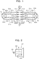
- Fig. 1 is a schematic plan configuration view of a pulverized coal burning boiler according to a first embodiment.
- four pulverized coal burners 61a to 61d are disposed in vessel front of the pulverized coal burning boiler 9 while four pulverized coal burners 61e to 61h are disposed in vessel back thereof so as to be opposite to the four pulverized coal burners 61a and 61d respectively.
- Two mills 3 are disposed in vessel front and in vessel back, respectively.
- Four coal feeding pipes 43a to 43d extended from the vessel front mill 3a are connected to the pulverized coal burners 61a to 61d respectively while four coal feeding pipes 43e to 43h extended from the vessel back mill 3b are connected to the pulverized coal burners 61e to 61h respectively.
- Pulverized coal flowmeters 51a to 51h are attached to the coal feeding pipes 43a to 43h respectively so that the flow rates of pulverized coal passing through the coal feeding pipes 43 can be measured individually.
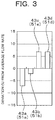
- Fig. 2 is a schematic configuration view of a pulverized coal burner 61.
- a pulverized coal nozzle 8 is disposed in the central portion of the pulverized coal burner 61.
- a combustion air supply path 63 for supplying combustion air (secondary air and tertiary air) 62 other than primary air is provided in an outer circumferential portion of the pulverized coal nozzle 8 individually in accordance with each burner 61.
- Combustion air supply amount adjusting means 64 (see Fig. 4 ), for example, of a dumper type or a slide type for adjusting the amount of supplied combustion air 62 is provided in an intermediate portion of the combustion air supply path 63. As shown in Fig.
- combustion air 62 of a low excess air ratio is supplied from the combustion air supply path 63 to thereby ignite and burn pulverized coal.
- combustion air 62 is supplied to the outer circumference of the pulverized coal nozzle 8
- the invention is not limited thereto as long as the combustion air 62 can be supplied so that pulverized coal jetted from the pulverized coal nozzle 8 into the furnace can be burned.
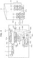
- Fig. 3 is a graph showing an example of deviations from an average flow rate in the case where pulverized coal obtained by supplying raw coal at a rate of X(t/h) to one mill 3 and milling the raw coal in the mill 3 is distributed to coal feeding pipes 43a to 43d so that the flow rates of pulverized coal are measured by pulverized coal flowmeters 51a to 51d respectively.
- 0% deviation means detection of pulverized coal at the average flow rate (X/4 in this example).
- This example shows that pulverized coal at flow rates lower than the average flow rate is conveyed to the coal feeding pipes 43a and 43b while pulverized coal at flow rates higher than the average flow rate is conveyed to the coal feeding pipes 43c and 43d.
- the deviation of the measured value is caused by a pressure loss difference based on the pipe length difference between the coal feeding pipes 43, the structure of the mill, etc. It is confirmed that the deviation varies according to the operating condition of the mill such as the rotational velocity of the rotary classifier.
- a deviation state of the flow rate of pulverized coal conveyed by each coal feeding pipe 43 is detected, the amount of supplied combustion air corresponding to the amount of supplied pulverized coal is calculated based on the deviation individually for each burner so that the air ratio set by the burner air ratio setting means can be kept, and a control signal is transmitted to each combustion air supply amount adjusting means 64 to thereby adjust the amount of combustion air supplied to each burner 61 individually.
- FIG. 4 is a view for explaining a combustion air supply amount control system therefor.
- a right half of Fig. 4 is a view showing an example of arrangement of pulverized coal burners 61 and AAPs 65 on their downstream sides in the pulverized coal burning boiler 9.
- Each of vessel front and vessel back is separated into burner stages so that a large number of pulverized coal burners 61 are arranged side by side in accordance with each burner stage.
- AAPs 65 are provided separately in both vessel front and vessel back so that the AAPs 65 are arranged side by side correspondingly to the respective pulverized coal burners 61.
- FIG. 4 A left half of Fig. 4 is a view showing a combustion air supply amount control system for the pulverized coal burners 61.
- the amounts of pulverized coal distributed and supplied from the mill 3 to the respective burners 61a and 61b as described above are measured individually by the pulverized coal flowmeters 51a and 51b, so that measured values thereof are input to a control circuit 66.
- combustion air supply amount adjusting means 64a and 64b and air flowmeters 67a and 67b are attached individually to intermediate portions of combustion air supply paths 63a and 63b provided correspondingly to the burners 61a and 61b respectively. Measured values of the amounts of air supplied to the burners 61a and 61b and measured individually by the air flowmeters 67a and 67b are also input to the control circuit 66. There is a mechanism that the control circuit 66 outputs combustion air supply amount control signals 68a and 68b to the combustion air supply amount adjusting means 64a and 64b individually.
- Fig. 5 is a block diagram showing an example of configuration of the control circuit 66. Values measured by the pulverized coal flowmeters 51a and 51b are input to the control circuit 66, so that deviation values from the average flow rate in the respective coal feeding pipes 43a and 43b are obtained by an adder 69 and dividers 70.
- a supplied coal amount 71, a burner air ratio 72, a theoretical air amount 73, combustion air amounts 74a and 74b for the respective burners, etc. are input to the control circuit 66 in advance.
- the burner air ratio 72 is set at 0.8 and the AAP air ratio is set at 0.3. Accordingly, the air ratio of the whole boiler is a low excess air ratio of 1.1.
- Combustion air supply amounts corresponding to the pulverized coal supply amounts are calculated and output as combustion air amount command values 68a and 68b based on the various set values and the deviation values of the pulverized coal amounts in the respective coal feeding pipes 43a and 43b so that the aforementioned burner air ratio can be kept.
- Various multipliers 76, subtracters 77, etc. in the control circuit 66 are used as means for calculating the command values 68a and 68b.
- Limiting items of correction amount limiters 75a and 75b provided on the output end side of the control circuit 66 are upper and lower limits of absolute values, change widths, and change ratios.
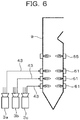
- Fig. 6 is a schematic configuration view of a pulverized coal burning boiler according to a second embodiment.
- mills 3a to 3c are disposed.
- the mills 3a, 3b and 3c are connected to upper-stage, middle-stage and lower-stage burners 61 respectively so that pulverized coal is supplied thereto.
- Fig. 7 is a view showing results of an experiment performed for specifying a burner stage large in CO reducing effect. This experiment was performed by use of a combustion analysis model having six burners in each burner stage.
- the amount of CO produced when pulverized coal (fuel) was equally distributed to burners in each burner stage was measured and regarded as a reference value (1.00) (see left columns in Fig. 7 ).
- a relative value of the amount of CO produced when deviation was given to the fuel supply amount so that the sum of deviation values (see Fig. 3 ) from the average flow rate of the six burners became 20% was shown in each central column in Fig. 7 .
- the amount of CO produced in the lower-stage burners little increased in spite of more or less deviation of the fuel supply amount whereas the amount of CO produced in the upper and middle stages increased by about 40% or more when there was deviation of the fuel supply amount.
- the increase in the amount of CO produced in the upper-stage burners was remarkable.
- this embodiment is configured so that the pulverized coal flowmeters 51, the control circuit 66, etc. are not attached to the lower stage but the pulverized coal flowmeters 51, the control circuit 66, etc. are attached to the upper and middle stages having a CO reducing effect, especially, to at least the upper stage to adjust the combustion air amount.
- the concentration p of pulverized coal passing through the coal feeding pipe 43 and the flow velocity V of the pulverized coal can be obtained as described above. Accordingly, the flow rate of primary air carrying pulverized coal can be calculated based on the concentration p and flow velocity V of the pulverized coal, the circulation sectional area S of the coal feeding pipe 43 and the temperature correction value. As the flow velocity V becomes higher, the flow rate of primary air, that is, the flow rate of primary air supplied to the burner 61 increases.
- this embodiment is configured so that the flow rate of primary air is calculated and the amount of supplied combustion air 62 is adjusted in consideration of the flow rate of primary air, for example, by means of reducing the amount of supplied combustion air 62 when the flow rate of primary air is high.
- calculation of the flow rate of primary air and adjustment of the amount of supplied combustion air 62 based on the calculation result are performed by the control circuit 66.
- This embodiment is particularly effective for a coal type such as subbituminous coal low in theoretical air amount because the rate of the amount of primary air in the coal type is higher than that in another coal type such as bituminous coal.
- the theoretical air amount of bituminous coal is 7.0 m 3 N/kg whereas the theoretical air amount of subbituminous coal is 5.5 m 3 N/kg which is small.
- Fig. 8 is a schematic configuration view of a pulverized coal burning boiler according to a fourth embodiment.
- Fig. 8(a) is a view showing the correspondence relation between pulverized coal burners 61 and AAPs 65.
- Fig. 8(b) is a view showing the arrangement of pulverized coal burners 61.
- Fig. 8(c) is a view showing the arrangement of AAPs 65.
- pulverized coal burners 61a to 61d in vessel front are disposed opposite to pulverized coal burners 61e to 61h in vessel back on a plane.
- AAPs 65a to 65d in vessel front are disposed opposite to AAPs 65e to 65h in vessel back on a plane.
- the AAPs 65 are disposed just above the pulverized coal burners 61 respectively.
- a burner combustion air amount adjustable range in each of the pulverized coal burners 61a to 61h is limited in advance from view of burner design.
- the adjustable range is limited to 10% of the rating burner combustion air amount.
- configuration is made so that the amount of burner combustion air supplied to the pulverized coal burner 61c increases by 10% and the amount of AAP air supplied to the AAP 65g on the opposite side increases by the remaining 3%.
- Fig. 9 is a view showing the CO reducing effect in this embodiment.
- a fuel deviation of +20% is detected in the pulverized coal burner 61c in the vessel-front upper stage.
- the CO relative value is 1.53 (see the upper stage in Fig. 7 ). Accordingly, when the amount of burner combustion air supplied to the pulverized coal burner 61c increased by 10%, the relative value of CO decreased to 0.75 (see the right of the upper stage in Fig. 9 ) so that the amount of CO could be reduced by 25% from the reference value.
- the amount of AAP air needs to cover the remaining 10%.
- the CO reducing effect in the case where the amount of air supplied to the vessel-front AAP 65c just above the pulverized coal burner 61c was increased by 10% and the CO reducing effect in the case where the amount of air supplied to the vessel-back AAP 65g on the side opposite to the pulverized coal burner 61c was increased by 10% were examined.
- the amount of air supplied to the vessel-front AAP 65c was increased, there was little effect (see the left of the lower stage in Fig. 9 ).
- Fig. 10 is a view showing the correspondence relation between pulverized coal burners 61 and AAPs 65 in a pulverized coal burning boiler according to a fifth embodiment.
- the number of AAPs 65 is larger than the number of pulverized coal burners 61, so that each pulverized coal burner 61 is disposed just below a midpoint between two AAPs 65.
- the amount of air supplied to the vessel-front pulverized coal burner 61b is increased, the amount of air supplied to the vessel-back AAPs 65g and 65h substantially opposite to the pulverized coal burner 61b, that is, nearest to flame formed by the pulverized coal burner 61b is increased while divided into two equal parts for the vessel-back AAPs 65g and 65h.
- Configuration is made so that when the amount of air supplied to the vessel-front pulverized coal burner 61c is increased, air is increased while divided into two equal parts for the vessel-back AAPs 65h and 65i substantially opposite to the pulverized coal burner 61c.
Landscapes
- Engineering & Computer Science (AREA)
- Physics & Mathematics (AREA)
- General Engineering & Computer Science (AREA)
- General Physics & Mathematics (AREA)
- Mechanical Engineering (AREA)
- Chemical & Material Sciences (AREA)
- Combustion & Propulsion (AREA)
- Fluid Mechanics (AREA)
- Thermal Sciences (AREA)
- Electromagnetism (AREA)
- Aviation & Aerospace Engineering (AREA)
- Regulation And Control Of Combustion (AREA)
- Measuring Volume Flow (AREA)
Claims (13)
- Mit Kohlenstaub befeuerter Dampferzeuger, umfassend:Mahlmittel (3), die durch Mahlen zugeführter Kohle Kohlenstaub erzeugen;Kohlezuführrohre (43), die in einer solchen Weise angeordnet sind, dass mehrere Kohlezuführrohre mit je einem Mahlmittel verbunden sind, und durch die der Kohlenstaub mit Primärluft als Tragluft gefördert wird;Kohlenstaubbrenner (61), die jeweils mit vorderen Enden der Kohlezuführrohre verbunden sind und die Kohlenstaubdüsen (8) haben, die so angeordnet sind, dass sie in einen Brennraum weisen;Verbrennungsluft-Zuführmittel (63), die Verbrennungsluft, die nicht die Primärluft ist, einzeln an die Kohlenstaubbrenner (61) liefern;Verbrennungsluft-Zuführmengen-Messmittel (67), die die Zuführmengen der von den Verbrennungsluft-Zuführmitteln zugeführten Verbrennungsluft einzeln messen;Verbrennungsluft-Zuführmengen-Einstellmittel (64), die die Zuführmengen der Verbrennungsluft einstellen; undBrennerluftverhältnis-Einstellmittel (72), die Brennerluftverhältnisse einstellen;wobei in den Mahlmitteln (3) gemahlener und erzeugter Kohlenstaub an die Kohlezuführrohre (43) verteilt wird, aus den Kohlenstaubdüsen (8) in den Brennraum eingedüst wird und unter der Zufuhr der Verbrennungsluft verbrannt wird;der mit Kohlenstaub befeuerte Dampferzeuger ferner umfasst:Kohlenstaub-Zuführmengen-Messmittel (51), die die Zuführmengen durch die Kohlezuführrohre geförderten Kohlenstaubs jeweils einzeln messen; undferner umfassend ein Luft-Zuführmengen-Steuerungsmittel (66),dadurch gekennzeichnet, dass das Luft-Zuführmengen-Steuerungsmittel (66) auf Basis der Zuführmengen von den Kohlenstaub-Zuführmengen-Messmitteln (51) gemessenen Kohlenstaubs eine Abweichung der Strömungsrate des von jedem Kohlezuführrohr (54) geförderten Kohlenstaubs von einer durchschnittlichen Strömungsrate des von allen Kohlezuführrohren (43) geförderten Kohlenstaubs erfasst; die Menge zugeführter Verbrennungsluft, die der Menge an Kohlenstaub entspricht, auf Basis der Abweichung für jeden Kohlenstaubbrenner (61) einzeln berechnet, sodass das von den Brennerluftverhältnis-Einstellmitteln (72) eingestellte Luftverhältnis aufrechterhalten werden kann; und ein Steuersignal an jedes Verbrennungsluft-Zuführmengen-Einstellmittel (64) sendet, um dadurch die Menge an jeden Kohlenstaubbrenner (61) gelieferter Verbrennungsluft jeweils einzeln einzustellen.
- Mit Kohlenstaub befeuerter Dampferzeuger gemäß Anspruch 1, dadurch gekennzeichnet, dass die Kohlenstaub-Zuführmengen-Messmittel (51) an den Kohlezuführrohren (43) von Kohlenstaubbrennern (61) oder Kohlenstaubbrennergruppen angebracht sind, deren Effekt der Verringerung des Anteils unverbrannter Kohle in den Kohlenstaubbrennern hoch ist, sodass die Zuführmengen von Verbrennungsluft einzeln eingestellt werden.
- Mit Kohlenstaub befeuerter Dampferzeuger gemäß Anspruch 1, dadurch gekennzeichnet, dass die Kohlenstaubbrenner (61) als mehrere Stufen für die Brennräume angeordnet sind und die Kohlenstaub-Zuführmengen-Messmittel (51) an den Kohlezuführrohren (43) der Kohlenstaubbrenner außer den auf der unteren Stufe angeordneten Kohlenstaubbrennern angebracht sind, sodass die Zuführmengen von Verbrennungsluft einzeln eingestellt werden.
- Mit Kohlenstaub befeuerter Dampferzeuger gemäß Anspruch 1, dadurch gekennzeichnet, dass die Kohlenstaubbrenner (61) als mehrere Stufen für den Brennraum angeordnet sind und die Kohlenstaub-Zuführmengen-Messmittel (51) an den Kohlezuführrohren (43) der Kohlenstaubbrenner angebracht sind, die zumindest an der obersten Stufe angeordnet sind, sodass die Zuführmengen von Verbrennungsluft einzeln eingestellt werden.
- Mit Kohlenstaub befeuerter Dampferzeuger gemäß Anspruch 1, dadurch gekennzeichnet, dass mehrere Kohlenstaubbrenner (61) nebeneinander angeordnet sind, um eine Brennerstufe auszubilden, mehrere Nachluftöffnungen (65) nebeneinander in einer Rauchgasströmungsrichtung auf einer stromabwärts gelegenen Seite der Brennerstufe angeordnet sind,die Menge an Verbrennungsluft, die an mindestens einen der Kohlenstaubbrenner (61) geliefert wird, eingestellt wird, unddie Menge an Verbrennungsluft, die an einen Nachluftanschluss (65) nahe der Flamme geliefert wird, die von dem Kohlenstaubbrenner (61) ausgebildet wird, eingestellt wird.
- Mit Kohlenstaub befeuerter Dampferzeuger gemäß Anspruch 5, dadurch gekennzeichnet, dass die mehreren Kohlenstaubbrenner (61) und die mehreren Nachluftöffnungen (65) so angeordnet sind, dass sie auf eine Feuerraumvorder- und eine Feuerraumrückseite eines Brennraums aufgeteilt sind,wenn die Menge an Verbrennungsluft, die an die an der Feuerraumvorderseite angeordneten Kohlenstaubbrenner (61) geliefert wird, eingestellt wird, die Menge an Verbrennungsluft, die an die an der Feuerraumrückseite angeordneten Nachluftöffnungen geliefert wird, eingestellt wird, undwenn die Menge an Verbrennungsluft, die an die an der Feuerraumrückseite angeordneten Kohlenstaubbrenner (61) geliefert wird, eingestellt wird, die Menge an Verbrennungsluft, die an die an der Feuerraumvorderseite angeordneten Nachluftöffnungen (65) geliefert wird, eingestellt wird.
- Mit Kohlenstaub befeuerter Dampferzeuger gemäß Anspruch 1, dadurch gekennzeichnet, dass mehrere Nachluftöffnungen (65) dispersiv auf einer in einer Rauchgasströmungsrichtung stromabwärts gelegenen Seite der Kohlenstaubbrenner (61) angeordnet sind, Konzentrations-Verteilungs-Erfassungsmittel (80, 81) zum Erfassen einer Verteilung von Sauerstoffkonzentrationen oder CO-Konzentrationen im Rauchgas in einem Kamin (82) auf einer in einer Rauchgasströmungsrichtung stromabwärts gelegenen Seite der Nachluftöffnungen (65) vorgesehen sind, und
während die Menge an Verbrennungsluft, die an die Kohlenstaubbrenner (61) geliefert wird, eingestellt wird, die Menge an Verbrennungsluft, die an die Nachluftöffnungen (65) geliefert wird, die einem Bereich mit niedriger Sauerstoffkonzentration oder hoher CO-Konzentration entsprechen, der von den Konzentrations-Verteilungs-Erfassungsmitteln (80, 81) erfasst wird, erhöht wird. - Mit Kohlenstaub befeuerter Dampferzeuger gemäß Anspruch 1, dadurch gekennzeichnet, dass jedes der Kohlenstaub-Zuführmengen-Messmittel (51) ein Mikrowellenresonanzrohr (43) hat, durch das ein gemischtes Fluid aus Kohlenstaub und Primärluft zirkuliert, und einen Mikrowellensender (52) und einen Mikrowellenempfänger (53), die in dem Mikrowellenresonanzrohr angeordnet sind, sodass sie in einer Strömungsrichtung des gemischten Fluids in einem vorbestimmten Abstand voneinander sind, und
der Mikrowellensender (52) Mikrowellen an den Mikrowellenempfänger (53) sendet, um eine Resonanzfrequenz des Mikrowellenresonanzrohrs zu messen, um dadurch auf Basis der Resonanzfrequenz die Zuführmenge des Kohlenstaubs zu messen. - Mit Kohlenstaub befeuerter Dampferzeuger gemäß Anspruch 8, dadurch gekennzeichnet, dass der Mikrowellensender (52) und der Mikrowellenempfänger (53) in das Mikrowellenresonanzrohr (43) hinein vorstehen, und ein Klopfelement auf einer stromaufwärts gelegenen Seite des Mikrowellensenders im Mikrowellenresonanzrohr angeordnet ist, um eine Strömung des Kohlenstaubs, die in dem Mikrowellenresonanzrohr wie ein Strang kondensiert ist, aufzutrennen.
- Mit Kohlenstaub befeuerter Dampferzeuger gemäß Anspruch 1, dadurch gekennzeichnet, dass die Kohlenstaub-Zuführmengen-Messmittel (51) einen ersten Ladungssensor (54a) und einen zweiten Ladungssensor (54b) haben, die in jedem der Kohlezuführrohre (43) angeordnet sind, sodass sie entlang einer axialen Richtung des Kohlezuführrohrs in einem vorbestimmten Abstand voneinander sind, und
eine Bewegung elektrostatischer Ladungen, die aus dem Durchfluss von Kohlenstaub in dem Kohlezuführrohr resultieren, von den beiden Ladungssensoren (54a, 54b) gemessen wird, sodass die Zuführmenge von Kohlenstaub auf Basis der Bewegung elektrostatischer Ladungen gemessen wird, die von den beiden Ladungssensoren gemessen wird. - Mit Kohlenstaub befeuerter Dampferzeuger gemäß Anspruch 10, dadurch gekennzeichnet, dass der erste Ladungssensor (54a) und der zweite Ladungssensor (54b) kreisförmig sind und Fluidführungsmittel (88) auf einer stromaufwärts gelegenen Seite der Ladungssensoren (54a, b) zum Sammeln von Kohlenstaub und zum Schütten des gesammelten Kohlenstaubs in einen Mittelteil (92) des Kohlezuführrohrs vorgesehen sind, um dadurch die Menge an Kohlenstaub zu verringern, die durch eine Innenumfangsseite der Ladungssensoren gelangt.
- Mit Kohlenstaub befeuerter Dampferzeuger gemäß Anspruch 1, ferner umfassend:einen Zwischenüberhitzer, der ein erstes Zwischenüberhitzersystem (103) und ein zweites Zwischenüberhitzersystem (104) aufweist, die nebeneinander angeordnet sind;wobei Dampf aus einer Hochdruckturbine von dem Zwischenüberhitzer erhitzt und an Mitteldruck- und Niederdruckturbinen geliefert wird, wobei der mit Kohlenstaub befeuerte Dampferzeuger ferner umfasst:Zwischenüberhitzer-Dampf-Verteilungsmengen-Einstellmittel (111, 112), die die Mengen von Dampf einstellen, die an das erste und das zweite Zwischenüberhitzersystem verteilt werden;Zwischenüberhitzer-Auslass-Dampf-Temperatur-Messmittel (113, 114), die Zwischenüberhitzer-Auslass-Dampf-Temperaturen des ersten und des zweiten Zwischenüberhitzersystems messen; undZwischenüberhitzer-Dampf-Verteilungsmengen-Steuermittel (120), die Steuerbefehlssignale an die Zwischenüberhitzer-Dampf-Verteilungsmengen-Einstellmittel senden, um die Temperaturdifferenz, die auf einer Abweichung zwischen den von den Zwischenüberhitzer-Auslass-Dampf-Temperatur-Messmitteln gemessenen Zwischenüberhitzer-Auslass-Dampf-Temperaturen basiert, zu eliminieren.
- Mit Kohlenstaub befeuerter Dampferzeuger gemäß Anspruch 1, ferner umfassend:einen Überhitzer, der ein erstes Überhitzersystem (204) und ein zweites Überhitzersystem (205) aufweist, die nebeneinander angeordnet sind;wobei Dampf von dem Überhitzer überhitzt und an eine Hochdruckturbine geliefert wird;wobei der mit Kohlenstaub befeuerte Dampferzeuger ferner umfasst:Überhitzungs-Dampf-Verteilungsmengen-Einstellmittel (215, 216), die die Mengen von Dampf einstellen, die an das erste und das zweite Überhitzersystem geliefert werden;Überhitzungs-Auslass-Dampf-Temperatur-Messmittel (217, 218), die Überhitzungs-Auslass-Dampf-Temperaturen des ersten und des zweiten Überhitzersystems messen; undÜberhitzungs-Dampf-Verteilungsmengen-Steuermittel (226), die Steuerbefehlssignale an die Überhitzungs-Dampf-Verteilungsmengen-Einstellmittel senden, um die Temperaturdifferenz, die auf einer Abweichung zwischen den von den Überhitzer-Auslass-Dampf-Temperatur-Messmitteln gemessenen Überhitzer-Auslass-Dampf-Temperaturen basiert, zu eliminieren.
Priority Applications (1)
| Application Number | Priority Date | Filing Date | Title |
|---|---|---|---|
| PL08740281T PL2143997T3 (pl) | 2007-04-13 | 2008-04-11 | Kocioł do spalania pyłu węglowego |
Applications Claiming Priority (2)
| Application Number | Priority Date | Filing Date | Title |
|---|---|---|---|
| JP2007105973 | 2007-04-13 | ||
| PCT/JP2008/057184 WO2008133051A1 (ja) | 2007-04-13 | 2008-04-11 | 微粉炭焚きボイラ |
Publications (3)
| Publication Number | Publication Date |
|---|---|
| EP2143997A1 EP2143997A1 (de) | 2010-01-13 |
| EP2143997A4 EP2143997A4 (de) | 2013-06-12 |
| EP2143997B1 true EP2143997B1 (de) | 2019-09-18 |
Family
ID=39925510
Family Applications (1)
| Application Number | Title | Priority Date | Filing Date |
|---|---|---|---|
| EP08740281.4A Active EP2143997B1 (de) | 2007-04-13 | 2008-04-11 | Kessel zum verbrennen von feinem kohlenstaub |
Country Status (8)
| Country | Link |
|---|---|
| US (1) | US20110197831A1 (de) |
| EP (1) | EP2143997B1 (de) |
| JP (1) | JP4855518B2 (de) |
| KR (1) | KR101232696B1 (de) |
| CN (1) | CN101663537B (de) |
| CA (1) | CA2683873C (de) |
| PL (1) | PL2143997T3 (de) |
| WO (1) | WO2008133051A1 (de) |
Families Citing this family (31)
| Publication number | Priority date | Publication date | Assignee | Title |
|---|---|---|---|---|
| US7810400B2 (en) | 2007-07-24 | 2010-10-12 | Cidra Corporate Services Inc. | Velocity based method for determining air-fuel ratio of a fluid flow |
| US20100316964A1 (en) * | 2009-06-11 | 2010-12-16 | Alstom Technology Ltd | Solids flow meter for integrated boiler control system |
| US8250933B2 (en) | 2010-03-30 | 2012-08-28 | Alstom Technology Ltd | Method and system for measurement of a flow rate of a fluid |
| WO2012034573A1 (de) * | 2010-09-16 | 2012-03-22 | Loesche Gmbh | Feststoffgefeuerter heissgaserzeuger mit erweitertem regelbereich |
| KR20140003558A (ko) * | 2011-01-21 | 2014-01-09 | 바브콕-히다찌 가부시끼가이샤 | 고체연료 버너 및 상기 버너를 이용하는 연소장치 |
| US9684653B1 (en) | 2012-03-06 | 2017-06-20 | Amazon Technologies, Inc. | Foreign language translation using product information |
| JP6044973B2 (ja) * | 2012-04-16 | 2016-12-14 | 一般財団法人電力中央研究所 | ボイラにおける混炭燃料の燃焼方法 |
| KR101453604B1 (ko) * | 2012-07-13 | 2014-10-21 | 주식회사 포스코 | 미분탄 제조설비의 에어히터 장치 및 이를 이용한 온도 제어방법 |
| CN102853419A (zh) * | 2012-08-29 | 2013-01-02 | 北京和隆优化控制技术有限公司 | 一种煤粉炉智能优化控制系统 |
| FI125166B (en) * | 2013-04-08 | 2015-06-30 | Outotec Oyj | PROCEDURES AND ARRANGEMENTS FOR FEEDING RAW MATERIAL FROM A RAW MATERIAL CONTAINER INTO A OVEN OVEN SPACE |
| US9523285B2 (en) | 2013-12-13 | 2016-12-20 | Chromalox, Inc. | Energy storage systems with medium voltage electrical heat exchangers |
| JP6372171B2 (ja) * | 2014-05-30 | 2018-08-15 | 株式会社Ihi | ボイラ装置及びボイラ装置の制御方法 |
| US10375901B2 (en) | 2014-12-09 | 2019-08-13 | Mtd Products Inc | Blower/vacuum |
| CN105157056B (zh) * | 2015-07-03 | 2018-09-18 | 杭州和利时自动化有限公司 | 一种确定锅炉燃烧系统的总风量的方法 |
| CN105135402A (zh) * | 2015-09-17 | 2015-12-09 | 杨晓方 | 一种锅炉装置 |
| CN105510625B (zh) * | 2015-11-27 | 2019-12-13 | 山东电力研究院 | 一种燃煤锅炉送粉管道含粉气流风速测量系统及方法 |
| KR101727257B1 (ko) * | 2016-09-09 | 2017-04-14 | 주식회사 지스코 | 보일러 설비 및 이의 운전 방법 |
| JP6599307B2 (ja) * | 2016-12-28 | 2019-10-30 | 三菱日立パワーシステムズ株式会社 | 燃焼装置及びそれを備えたボイラ |
| WO2018120256A1 (zh) * | 2016-12-28 | 2018-07-05 | 邸生才 | 按煤粉重量均衡供粉和按重量配风控制装置及其控制方法 |
| DE102017009393B3 (de) * | 2017-10-11 | 2019-01-24 | Promecon Process Measurement Control Gmbh | Einrichtung zur Steuerung des Verbrennungsprozesses in einer Kraftwerksfeuerungsanlage |
| US11366089B2 (en) * | 2018-03-14 | 2022-06-21 | Mitsubishi Heavy Industries, Ltd. | Analysis condition adjusting device of simple fuel analyzer |
| CN108954372A (zh) * | 2018-07-31 | 2018-12-07 | 大唐东北电力试验研究院有限公司 | 一种锅炉一次风在线调平系统 |
| JP7223565B2 (ja) * | 2018-11-26 | 2023-02-16 | 三菱重工業株式会社 | 固体燃料供給装置および方法並びに粉砕機、ボイラ |
| CN111306571B (zh) * | 2018-12-12 | 2024-12-20 | 邸生才 | 应用入炉煤粉热量测量系统的锅炉燃烧控制系统 |
| US10648841B1 (en) * | 2019-03-08 | 2020-05-12 | Saudi Arabian Oil Company | Multiphase flow meter combining extended throat venturi with microwave resonators |
| CN110595555B (zh) * | 2019-09-27 | 2020-09-01 | 江苏方天电力技术有限公司 | 一种基于实时煤质情况的烟道烟气流量分配在线监测方法 |
| JP7365293B2 (ja) * | 2020-05-19 | 2023-10-19 | 三菱重工業株式会社 | 固体燃料焚きボイラ、固体燃料供給量計測装置、燃焼方法及びプログラム |
| CN112934449B (zh) * | 2021-03-05 | 2023-09-12 | 华能国际电力股份有限公司大连电厂 | 一种中速磨进煤管在线称重防堵机构及控制方法 |
| CN114413244B (zh) * | 2022-02-09 | 2024-05-14 | 上海电气风电集团股份有限公司 | 火电机组和炉膛助燃装置 |
| CN115095882A (zh) * | 2022-07-04 | 2022-09-23 | 华能临沂发电有限公司 | 煤粉动态调节系统 |
| JP2024059410A (ja) * | 2022-10-18 | 2024-05-01 | 中国電力株式会社 | ボイラ制御装置、プログラム、ボイラ制御方法 |
Family Cites Families (25)
| Publication number | Priority date | Publication date | Assignee | Title |
|---|---|---|---|---|
| US4540129A (en) * | 1982-11-12 | 1985-09-10 | The Babcock & Wilcox Company | Pulverizer control system |
| US4512200A (en) * | 1983-11-30 | 1985-04-23 | The Babcock & Wilcox Company | Pulverized coal relative distribution meter |
| JPS60221616A (ja) | 1984-04-18 | 1985-11-06 | Babcock Hitachi Kk | 微粉炭供給装置 |
| JPS6127408A (ja) * | 1984-07-17 | 1986-02-06 | 株式会社日立製作所 | スプレ−水調節方式 |
| US4726235A (en) * | 1986-03-12 | 1988-02-23 | Available Energy, Inc. | Ultrasonic instrument to measure the gas velocity and/or the solids loading in a flowing gas stream |
| CN86103084A (zh) * | 1986-05-14 | 1988-01-27 | 冶金部自动化研究所 | 气动输送煤粉流量检测方法及装置 |
| US4887958A (en) * | 1986-10-10 | 1989-12-19 | Hagar Donald K | Method and system for controlling the supply of fuel and air to a furnace |
| JPH07109296B2 (ja) * | 1986-12-22 | 1995-11-22 | バブコツク日立株式会社 | 蒸気発生装置 |
| US5048761A (en) * | 1990-03-14 | 1991-09-17 | The Babcock & Wilcox Company | Pulverized coal flow monitor and control system and method |
| JP3015602B2 (ja) * | 1992-09-17 | 2000-03-06 | 三菱重工業株式会社 | 蒸気温度制御装置 |
| JPH06317304A (ja) * | 1993-05-06 | 1994-11-15 | Mitsubishi Heavy Ind Ltd | 自動バイアス回路による蒸気温度制御装置 |
| DE4426280A1 (de) * | 1994-07-25 | 1996-02-01 | Reich Ernst | Verfahren zum Ermitteln der Beladung eines Gasstroms mit Feststoffanteilen |
| DE19504544A1 (de) * | 1995-02-11 | 1996-08-14 | Reich Ernst | Verfahren zum Ermitteln der Beladung eines Gasstroms mit Feststoffanteilen |
| JPH08270931A (ja) | 1995-03-29 | 1996-10-18 | Hitachi Ltd | 微粉炭燃焼装置及び燃焼方法 |
| JP3100311B2 (ja) | 1995-07-03 | 2000-10-16 | 三菱重工業株式会社 | ボイラの再熱蒸気系統 |
| CN2248296Y (zh) * | 1995-09-29 | 1997-02-26 | 茅群龙 | 火电厂仓储式制粉系统入炉煤粉量在线测控装置 |
| US6186079B1 (en) * | 1999-08-31 | 2001-02-13 | Sure Alloy Steel Corporation | Linear diffuser for balancing coal flow |
| DE10164109C2 (de) * | 2001-12-24 | 2003-10-30 | Baumgarten Heinrich Kg | Verfahren zur Herstellung von Dichtleisten oder Dichtringen aus profilierten Bändern |
| US6659026B1 (en) * | 2002-01-30 | 2003-12-09 | Aep Emtech Llc | Control system for reducing NOx emissions from a multiple-intertube pulverized-coal burner using true delivery pipe fuel flow measurement |
| GB2388905B (en) * | 2002-03-15 | 2005-10-26 | Abb Ltd | Improvements in flow metering |
| US7100423B2 (en) * | 2003-09-04 | 2006-09-05 | Midwest Research Institute | Method and apparatus for monitoring particles in a flowing gas |
| JP4444791B2 (ja) * | 2004-11-04 | 2010-03-31 | バブコック日立株式会社 | 燃料燃焼用空気ポート、その製造方法及びボイラ |
| AU2005229668B2 (en) * | 2004-11-04 | 2008-03-06 | Babcock-Hitachi K.K. | Overfiring air port, method for manufacturing air port, boiler, boiler facility, method for operating boiler facility and method for improving boiler facility |
| JP4664179B2 (ja) * | 2005-10-17 | 2011-04-06 | バブコック日立株式会社 | ボイラ設備及びボイラ設備の運転方法並びにボイラ設備の改修方法 |
| US8505472B2 (en) * | 2006-01-11 | 2013-08-13 | Babcock-Hitachi K.K. | Pulverized coal-fired boiler and pulverized coal burning method |
-
2008
- 2008-04-11 JP JP2009511783A patent/JP4855518B2/ja active Active
- 2008-04-11 EP EP08740281.4A patent/EP2143997B1/de active Active
- 2008-04-11 CA CA2683873A patent/CA2683873C/en active Active
- 2008-04-11 PL PL08740281T patent/PL2143997T3/pl unknown
- 2008-04-11 US US12/594,997 patent/US20110197831A1/en not_active Abandoned
- 2008-04-11 WO PCT/JP2008/057184 patent/WO2008133051A1/ja not_active Ceased
- 2008-04-11 KR KR1020097021323A patent/KR101232696B1/ko active Active
- 2008-04-11 CN CN2008800116119A patent/CN101663537B/zh not_active Expired - Fee Related
Non-Patent Citations (1)
| Title |
|---|
| None * |
Also Published As
| Publication number | Publication date |
|---|---|
| PL2143997T3 (pl) | 2020-01-31 |
| CN101663537B (zh) | 2012-01-11 |
| CN101663537A (zh) | 2010-03-03 |
| CA2683873A1 (en) | 2008-11-06 |
| KR101232696B1 (ko) | 2013-02-13 |
| JP4855518B2 (ja) | 2012-01-18 |
| US20110197831A1 (en) | 2011-08-18 |
| WO2008133051A1 (ja) | 2008-11-06 |
| KR20100003288A (ko) | 2010-01-07 |
| CA2683873C (en) | 2013-01-15 |
| JPWO2008133051A1 (ja) | 2010-07-22 |
| EP2143997A1 (de) | 2010-01-13 |
| EP2143997A4 (de) | 2013-06-12 |
Similar Documents
| Publication | Publication Date | Title |
|---|---|---|
| CA2683873C (en) | Pulverized coal burning boiler | |
| US6622645B2 (en) | Combustion optimization with inferential sensor | |
| CN102425807B (zh) | 一种煤粉锅炉燃烧前馈反馈复合优化控制方法 | |
| CN105276611B (zh) | 火电厂锅炉燃烧调整优化方法与系统 | |
| CN101939589B (zh) | 具有闭路火焰温度控制的氧气燃料燃烧系统 | |
| CN105783025B (zh) | 一种监测低NOx切向燃煤锅炉炉内风粉分布的方法 | |
| CN103807852B (zh) | 煤粉锅炉的二次风配风装置及二次风配风方法 | |
| Blondeau et al. | Burner air-fuel ratio monitoring in large pulverised-fuel boilers using advanced sensors: Case study of a 660 MWe coal-fired power plant | |
| EP3564583B1 (de) | Brenner und damit ausgestatteter kessel | |
| KR101623201B1 (ko) | 화력발전소의 콜유량 균등분배를 위한 미분탄 공급 관로 유량측정 방법 | |
| CN204042968U (zh) | 煤粉锅炉数字化燃烧控制和优化系统 | |
| US6659026B1 (en) | Control system for reducing NOx emissions from a multiple-intertube pulverized-coal burner using true delivery pipe fuel flow measurement | |
| CN204084340U (zh) | 煤粉锅炉的二次风配风装置 | |
| CN111457418A (zh) | 一种基于燃尽风减轻双切圆锅炉炉膛出口烟气速度偏差的方法 | |
| CN111306571B (zh) | 应用入炉煤粉热量测量系统的锅炉燃烧控制系统 | |
| JPH0255685B2 (de) | ||
| CN115727350A (zh) | 一种二维温度场燃烧控制方法及系统 | |
| CN104214792B (zh) | 实现直流锅炉给水流量与燃料量动态精确配比的补偿方法 | |
| Sarunac et al. | SENSOR AND CONTROL CHALLENGES FOR IMPROVED COMBUSTION CONTROL, PERFORMANCE AND REDUCED POWER PLANT EMISSIONS | |
| HK1151336B (en) | Oxy-fuel combustion system with closed loop flame temperature control | |
| Zhang | Optimization of Control and Combustion On a 330MW Face-fired Boiler | |
| JPH0229506A (ja) | 燃焼制御装置 | |
| Lisauskas et al. | Riley Stoker Corporation |
Legal Events
| Date | Code | Title | Description |
|---|---|---|---|
| PUAI | Public reference made under article 153(3) epc to a published international application that has entered the european phase |
Free format text: ORIGINAL CODE: 0009012 |
|
| 17P | Request for examination filed |
Effective date: 20091110 |
|
| AK | Designated contracting states |
Kind code of ref document: A1 Designated state(s): AT BE BG CH CY CZ DE DK EE ES FI FR GB GR HR HU IE IS IT LI LT LU LV MC MT NL NO PL PT RO SE SI SK TR |
|
| DAX | Request for extension of the european patent (deleted) | ||
| A4 | Supplementary search report drawn up and despatched |
Effective date: 20130514 |
|
| RIC1 | Information provided on ipc code assigned before grant |
Ipc: F23L 9/02 20060101ALI20130506BHEP Ipc: G01F 1/66 20060101ALI20130506BHEP Ipc: F23N 3/02 20060101ALI20130506BHEP Ipc: F22G 5/00 20060101ALI20130506BHEP Ipc: F23N 5/00 20060101ALI20130506BHEP Ipc: G01P 5/20 20060101ALI20130506BHEP Ipc: G01F 1/712 20060101ALI20130506BHEP Ipc: F23N 1/02 20060101ALI20130506BHEP Ipc: G01F 1/74 20060101ALI20130506BHEP Ipc: F23C 99/00 20060101AFI20130506BHEP Ipc: F22B 35/00 20060101ALI20130506BHEP Ipc: F23K 3/02 20060101ALI20130506BHEP |
|
| RAP1 | Party data changed (applicant data changed or rights of an application transferred) |
Owner name: MITSUBISHI HITACHI POWER SYSTEMS, LTD. |
|
| STAA | Information on the status of an ep patent application or granted ep patent |
Free format text: STATUS: EXAMINATION IS IN PROGRESS |
|
| 17Q | First examination report despatched |
Effective date: 20180328 |
|
| GRAP | Despatch of communication of intention to grant a patent |
Free format text: ORIGINAL CODE: EPIDOSNIGR1 |
|
| STAA | Information on the status of an ep patent application or granted ep patent |
Free format text: STATUS: GRANT OF PATENT IS INTENDED |
|
| INTG | Intention to grant announced |
Effective date: 20190404 |
|
| GRAS | Grant fee paid |
Free format text: ORIGINAL CODE: EPIDOSNIGR3 |
|
| GRAA | (expected) grant |
Free format text: ORIGINAL CODE: 0009210 |
|
| STAA | Information on the status of an ep patent application or granted ep patent |
Free format text: STATUS: THE PATENT HAS BEEN GRANTED |
|
| AK | Designated contracting states |
Kind code of ref document: B1 Designated state(s): AT BE BG CH CY CZ DE DK EE ES FI FR GB GR HR HU IE IS IT LI LT LU LV MC MT NL NO PL PT RO SE SI SK TR |
|
| REG | Reference to a national code |
Ref country code: GB Ref legal event code: FG4D |
|
| REG | Reference to a national code |
Ref country code: CH Ref legal event code: EP |
|
| REG | Reference to a national code |
Ref country code: DE Ref legal event code: R096 Ref document number: 602008061223 Country of ref document: DE |
|
| REG | Reference to a national code |
Ref country code: AT Ref legal event code: REF Ref document number: 1181770 Country of ref document: AT Kind code of ref document: T Effective date: 20191015 |
|
| REG | Reference to a national code |
Ref country code: IE Ref legal event code: FG4D |
|
| REG | Reference to a national code |
Ref country code: NL Ref legal event code: MP Effective date: 20190918 |
|
| PG25 | Lapsed in a contracting state [announced via postgrant information from national office to epo] |
Ref country code: BG Free format text: LAPSE BECAUSE OF FAILURE TO SUBMIT A TRANSLATION OF THE DESCRIPTION OR TO PAY THE FEE WITHIN THE PRESCRIBED TIME-LIMIT Effective date: 20191218 Ref country code: LT Free format text: LAPSE BECAUSE OF FAILURE TO SUBMIT A TRANSLATION OF THE DESCRIPTION OR TO PAY THE FEE WITHIN THE PRESCRIBED TIME-LIMIT Effective date: 20190918 Ref country code: HR Free format text: LAPSE BECAUSE OF FAILURE TO SUBMIT A TRANSLATION OF THE DESCRIPTION OR TO PAY THE FEE WITHIN THE PRESCRIBED TIME-LIMIT Effective date: 20190918 Ref country code: SE Free format text: LAPSE BECAUSE OF FAILURE TO SUBMIT A TRANSLATION OF THE DESCRIPTION OR TO PAY THE FEE WITHIN THE PRESCRIBED TIME-LIMIT Effective date: 20190918 Ref country code: NO Free format text: LAPSE BECAUSE OF FAILURE TO SUBMIT A TRANSLATION OF THE DESCRIPTION OR TO PAY THE FEE WITHIN THE PRESCRIBED TIME-LIMIT Effective date: 20191218 Ref country code: FI Free format text: LAPSE BECAUSE OF FAILURE TO SUBMIT A TRANSLATION OF THE DESCRIPTION OR TO PAY THE FEE WITHIN THE PRESCRIBED TIME-LIMIT Effective date: 20190918 |
|
| REG | Reference to a national code |
Ref country code: LT Ref legal event code: MG4D |
|
| PG25 | Lapsed in a contracting state [announced via postgrant information from national office to epo] |
Ref country code: GR Free format text: LAPSE BECAUSE OF FAILURE TO SUBMIT A TRANSLATION OF THE DESCRIPTION OR TO PAY THE FEE WITHIN THE PRESCRIBED TIME-LIMIT Effective date: 20191219 Ref country code: LV Free format text: LAPSE BECAUSE OF FAILURE TO SUBMIT A TRANSLATION OF THE DESCRIPTION OR TO PAY THE FEE WITHIN THE PRESCRIBED TIME-LIMIT Effective date: 20190918 |
|
| REG | Reference to a national code |
Ref country code: AT Ref legal event code: MK05 Ref document number: 1181770 Country of ref document: AT Kind code of ref document: T Effective date: 20190918 |
|
| PG25 | Lapsed in a contracting state [announced via postgrant information from national office to epo] |
Ref country code: RO Free format text: LAPSE BECAUSE OF FAILURE TO SUBMIT A TRANSLATION OF THE DESCRIPTION OR TO PAY THE FEE WITHIN THE PRESCRIBED TIME-LIMIT Effective date: 20190918 Ref country code: IT Free format text: LAPSE BECAUSE OF FAILURE TO SUBMIT A TRANSLATION OF THE DESCRIPTION OR TO PAY THE FEE WITHIN THE PRESCRIBED TIME-LIMIT Effective date: 20190918 Ref country code: EE Free format text: LAPSE BECAUSE OF FAILURE TO SUBMIT A TRANSLATION OF THE DESCRIPTION OR TO PAY THE FEE WITHIN THE PRESCRIBED TIME-LIMIT Effective date: 20190918 Ref country code: AT Free format text: LAPSE BECAUSE OF FAILURE TO SUBMIT A TRANSLATION OF THE DESCRIPTION OR TO PAY THE FEE WITHIN THE PRESCRIBED TIME-LIMIT Effective date: 20190918 Ref country code: NL Free format text: LAPSE BECAUSE OF FAILURE TO SUBMIT A TRANSLATION OF THE DESCRIPTION OR TO PAY THE FEE WITHIN THE PRESCRIBED TIME-LIMIT Effective date: 20190918 Ref country code: PT Free format text: LAPSE BECAUSE OF FAILURE TO SUBMIT A TRANSLATION OF THE DESCRIPTION OR TO PAY THE FEE WITHIN THE PRESCRIBED TIME-LIMIT Effective date: 20200120 Ref country code: ES Free format text: LAPSE BECAUSE OF FAILURE TO SUBMIT A TRANSLATION OF THE DESCRIPTION OR TO PAY THE FEE WITHIN THE PRESCRIBED TIME-LIMIT Effective date: 20190918 |
|
| PG25 | Lapsed in a contracting state [announced via postgrant information from national office to epo] |
Ref country code: IS Free format text: LAPSE BECAUSE OF FAILURE TO SUBMIT A TRANSLATION OF THE DESCRIPTION OR TO PAY THE FEE WITHIN THE PRESCRIBED TIME-LIMIT Effective date: 20200224 Ref country code: SK Free format text: LAPSE BECAUSE OF FAILURE TO SUBMIT A TRANSLATION OF THE DESCRIPTION OR TO PAY THE FEE WITHIN THE PRESCRIBED TIME-LIMIT Effective date: 20190918 Ref country code: CZ Free format text: LAPSE BECAUSE OF FAILURE TO SUBMIT A TRANSLATION OF THE DESCRIPTION OR TO PAY THE FEE WITHIN THE PRESCRIBED TIME-LIMIT Effective date: 20190918 |
|
| REG | Reference to a national code |
Ref country code: DE Ref legal event code: R097 Ref document number: 602008061223 Country of ref document: DE |
|
| PLBE | No opposition filed within time limit |
Free format text: ORIGINAL CODE: 0009261 |
|
| STAA | Information on the status of an ep patent application or granted ep patent |
Free format text: STATUS: NO OPPOSITION FILED WITHIN TIME LIMIT |
|
| PG2D | Information on lapse in contracting state deleted |
Ref country code: IS |
|
| PG25 | Lapsed in a contracting state [announced via postgrant information from national office to epo] |
Ref country code: DK Free format text: LAPSE BECAUSE OF FAILURE TO SUBMIT A TRANSLATION OF THE DESCRIPTION OR TO PAY THE FEE WITHIN THE PRESCRIBED TIME-LIMIT Effective date: 20190918 Ref country code: IS Free format text: LAPSE BECAUSE OF FAILURE TO SUBMIT A TRANSLATION OF THE DESCRIPTION OR TO PAY THE FEE WITHIN THE PRESCRIBED TIME-LIMIT Effective date: 20200119 |
|
| 26N | No opposition filed |
Effective date: 20200619 |
|
| PG25 | Lapsed in a contracting state [announced via postgrant information from national office to epo] |
Ref country code: SI Free format text: LAPSE BECAUSE OF FAILURE TO SUBMIT A TRANSLATION OF THE DESCRIPTION OR TO PAY THE FEE WITHIN THE PRESCRIBED TIME-LIMIT Effective date: 20190918 |
|
| REG | Reference to a national code |
Ref country code: DE Ref legal event code: R119 Ref document number: 602008061223 Country of ref document: DE |
|
| PG25 | Lapsed in a contracting state [announced via postgrant information from national office to epo] |
Ref country code: MC Free format text: LAPSE BECAUSE OF FAILURE TO SUBMIT A TRANSLATION OF THE DESCRIPTION OR TO PAY THE FEE WITHIN THE PRESCRIBED TIME-LIMIT Effective date: 20190918 |
|
| REG | Reference to a national code |
Ref country code: CH Ref legal event code: PL |
|
| PG25 | Lapsed in a contracting state [announced via postgrant information from national office to epo] |
Ref country code: FR Free format text: LAPSE BECAUSE OF NON-PAYMENT OF DUE FEES Effective date: 20200430 Ref country code: LU Free format text: LAPSE BECAUSE OF NON-PAYMENT OF DUE FEES Effective date: 20200411 Ref country code: LI Free format text: LAPSE BECAUSE OF NON-PAYMENT OF DUE FEES Effective date: 20200430 Ref country code: DE Free format text: LAPSE BECAUSE OF NON-PAYMENT OF DUE FEES Effective date: 20201103 Ref country code: CH Free format text: LAPSE BECAUSE OF NON-PAYMENT OF DUE FEES Effective date: 20200430 |
|
| REG | Reference to a national code |
Ref country code: BE Ref legal event code: MM Effective date: 20200430 |
|
| PG25 | Lapsed in a contracting state [announced via postgrant information from national office to epo] |
Ref country code: BE Free format text: LAPSE BECAUSE OF NON-PAYMENT OF DUE FEES Effective date: 20200430 |
|
| GBPC | Gb: european patent ceased through non-payment of renewal fee |
Effective date: 20200411 |
|
| PG25 | Lapsed in a contracting state [announced via postgrant information from national office to epo] |
Ref country code: IE Free format text: LAPSE BECAUSE OF NON-PAYMENT OF DUE FEES Effective date: 20200411 Ref country code: GB Free format text: LAPSE BECAUSE OF NON-PAYMENT OF DUE FEES Effective date: 20200411 |
|
| PG25 | Lapsed in a contracting state [announced via postgrant information from national office to epo] |
Ref country code: TR Free format text: LAPSE BECAUSE OF FAILURE TO SUBMIT A TRANSLATION OF THE DESCRIPTION OR TO PAY THE FEE WITHIN THE PRESCRIBED TIME-LIMIT Effective date: 20190918 Ref country code: MT Free format text: LAPSE BECAUSE OF FAILURE TO SUBMIT A TRANSLATION OF THE DESCRIPTION OR TO PAY THE FEE WITHIN THE PRESCRIBED TIME-LIMIT Effective date: 20190918 Ref country code: CY Free format text: LAPSE BECAUSE OF FAILURE TO SUBMIT A TRANSLATION OF THE DESCRIPTION OR TO PAY THE FEE WITHIN THE PRESCRIBED TIME-LIMIT Effective date: 20190918 |
|
| PGFP | Annual fee paid to national office [announced via postgrant information from national office to epo] |
Ref country code: PL Payment date: 20240315 Year of fee payment: 17 |