EP2144530B1 - Rail de guidage télescopique - Google Patents
Rail de guidage télescopique Download PDFInfo
- Publication number
- EP2144530B1 EP2144530B1 EP08759387.7A EP08759387A EP2144530B1 EP 2144530 B1 EP2144530 B1 EP 2144530B1 EP 08759387 A EP08759387 A EP 08759387A EP 2144530 B1 EP2144530 B1 EP 2144530B1
- Authority
- EP
- European Patent Office
- Prior art keywords
- rail
- coupling member
- sliding
- telescopic guide
- running
- Prior art date
- Legal status (The legal status is an assumption and is not a legal conclusion. Google has not performed a legal analysis and makes no representation as to the accuracy of the status listed.)
- Not-in-force
Links
- 230000008878 coupling Effects 0.000 claims description 66
- 238000010168 coupling process Methods 0.000 claims description 66
- 238000005859 coupling reaction Methods 0.000 claims description 66
- 238000006073 displacement reaction Methods 0.000 claims description 10
- 238000003780 insertion Methods 0.000 claims description 6
- 230000037431 insertion Effects 0.000 claims description 6
- 238000013016 damping Methods 0.000 claims description 4
- 238000000034 method Methods 0.000 claims description 4
- 230000008569 process Effects 0.000 claims description 4
- 230000008901 benefit Effects 0.000 description 2
- 230000002349 favourable effect Effects 0.000 description 2
- 230000005484 gravity Effects 0.000 description 2
- 238000005096 rolling process Methods 0.000 description 2
- 230000007704 transition Effects 0.000 description 2
- 230000002411 adverse Effects 0.000 description 1
- 230000001419 dependent effect Effects 0.000 description 1
- 239000000284 extract Substances 0.000 description 1
- 230000004048 modification Effects 0.000 description 1
- 238000012986 modification Methods 0.000 description 1
- 230000035515 penetration Effects 0.000 description 1
Images





Classifications
-
- A—HUMAN NECESSITIES
- A47—FURNITURE; DOMESTIC ARTICLES OR APPLIANCES; COFFEE MILLS; SPICE MILLS; SUCTION CLEANERS IN GENERAL
- A47B—TABLES; DESKS; OFFICE FURNITURE; CABINETS; DRAWERS; GENERAL DETAILS OF FURNITURE
- A47B88/00—Drawers for tables, cabinets or like furniture; Guides for drawers
- A47B88/40—Sliding drawers; Slides or guides therefor
- A47B88/49—Sliding drawers; Slides or guides therefor with double extensible guides or parts
- A47B88/493—Sliding drawers; Slides or guides therefor with double extensible guides or parts with rollers, ball bearings, wheels, or the like
-
- A—HUMAN NECESSITIES
- A47—FURNITURE; DOMESTIC ARTICLES OR APPLIANCES; COFFEE MILLS; SPICE MILLS; SUCTION CLEANERS IN GENERAL
- A47B—TABLES; DESKS; OFFICE FURNITURE; CABINETS; DRAWERS; GENERAL DETAILS OF FURNITURE
- A47B88/00—Drawers for tables, cabinets or like furniture; Guides for drawers
- A47B88/40—Sliding drawers; Slides or guides therefor
- A47B88/44—Sequencing or synchronisation of drawer slides or functional units
- A47B88/443—Successive movement of rails within drawer slides, i.e. at least one rail element is not moving during the movement of other elements
-
- A—HUMAN NECESSITIES
- A47—FURNITURE; DOMESTIC ARTICLES OR APPLIANCES; COFFEE MILLS; SPICE MILLS; SUCTION CLEANERS IN GENERAL
- A47B—TABLES; DESKS; OFFICE FURNITURE; CABINETS; DRAWERS; GENERAL DETAILS OF FURNITURE
- A47B2210/00—General construction of drawers, guides and guide devices
- A47B2210/0002—Guide construction for drawers
- A47B2210/0064—Guide sequencing or synchronisation
Definitions
- the present invention relates to a Teleskopfiihrungsschiene for furniture drawer extensions such as drawers or the like, comprising a fixable on a furniture carcass rail, connectable to a furniture drawer track and arranged between the carcass rail and the runner, aussverinrnde middle rail and a flow control, by means of which the running rail during extension the closed position as long as coupled to the middle rail until the middle rail has reached its maximum extension position and is blocked in this position with simultaneous decoupling of the running rail of the center rail relative to the carcass rail and the center rail only again against the carcass rail in the closing direction is displaced when the running rail is displaced maximally in the direction of insertion in relation to the initially blocked center rail and in the process is again coupled to the middle rail.
- Telescopic guide rails of the generic type are known in many embodiments.
- so-called “Quadro-extracts” known, in which rolling bodies are provided in the form of balls in the raceways.
- Such telescopic guide rails are particularly sustainable.
- telescopic guide rails of the generic type, in which the substantially C-shaped profiles of the carcass rail, the aussverinrnden middle rail and the running rail are arranged horizontally next to each other in the use position.
- sequence control different embodiments are also known, wherein the sequence controls are arranged in the region of the raceways of the telescopic guide rails.
- the carrying capacity of the telescopic guide rails can be adversely affected, especially if by the arrangement of a flow control part of the raceways can not be equipped with balls to increase the carrying capacity.
- Telescopic guide rails with a sequence control which are not arranged in the region of the raceways of the balls are also known.
- Such telescopic guide rails are disclosed in the patent documents DE 296 21 957 U1 and EP 0 620 993 A1 disclosed.
- the present invention has for its object to provide a telescopic guide rail of the generic type, which is characterized by a particularly simple and the carrying capacity of the telescopic guide rail in any way impairing flow control.
- a solution to this problem according to the invention is that the sequence control from a provided with two mirror images mutually sliding links provided coupling member and attached to the carcass rail and associated with a first of the link guides first sliding block and a second, attached to the running rail and the second link guide assigned Sliding block consists, wherein the coupling member is pivotally mounted about a perpendicular to the sliding plane of the telescopic guide rail extending axis and the slotted guides V-shaped spread apart such that when entering the first sliding block in the first link guide assigned to him a switching of the coupling member and an associated release causes the second sliding block from the associated second link guide and vice versa.
- This specified solution is intended for a telescopic guide rail, in which the carcass rail, the center rail and the running rail in the position of use are arranged vertically one above the other.
- the sequence control according to the invention can be arranged with great advantage outside of the raceway region of the individual rail elements and thus does not affect in any way the carrying capacity of the entire telescopic guide rail, especially not even if it is equipped with rolling elements in the form of balls in the raceways.
- the telescopic guide rail according to the invention is characterized in that the flow control has an extremely simple and uncomplicated structure and ultimately only from the coupling member with the slotted guides and on the body rail on the one hand and the running rail on the other hand connected sliding blocks exists.
- a further solution of the object according to the invention consists in that the sequence control consists of a coupling member provided with two mirror-symmetrical slide links and a first sliding block attached to the carcass rail and a first of the sliding guides and a second sliding guide fastened to the running rail and the second sliding guide associated sliding block consists, wherein the coupling member is pivotally mounted about an axis parallel to the sliding plane of the telescopic guide rail axis and the slide guides V-shaped spread apart extend such that when entering the first sliding block in the associated first link guide switching the coupling member and an associated Release of the second sliding block from the associated second link guide causes and vice versa.
- This solution is intended for a telescopic guide rail, in which the carcass rail, the center rail and the running rail in the position of use are arranged horizontally next to each other.
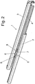
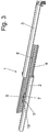
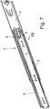
- FIGS. 1 to 3 is denoted by the reference numeral 1, a fully illustrated telescopic guide rail comprising a body side fixable carcass rail 2, a connectable to a pull-out part such as a drawer running rail 3 and arranged between the carcass rail 2 and the running rail 3, aussverinrnde center rail 4.
- the telescopic guide rail 1 is provided with a flow control 5, by means of which it is ensured that the running rail 3 can only be moved relative to the center rail 4, when the middle rail 4 is extended to its adjacent body rail 2 maximum, also can on the flow control. 5 be ensured that the center rail 4 from its fully extended position can only be moved back into the closed position when the running rail 3 has been moved back relative to the center rail 4 again maximally in the insertion direction.
- Such a sequence control 5 is desirable in order to avoid an uncontrolled displacement of the center rail 4 relative to the carcass rail 2 and / or the running rail 3, resulting in a favorable load on the rail components. Moreover, the controlled process has a very favorable influence on the operating force and the lowering.
- the sequence control 5 comprises a coupling member 6 and a first sliding block 7 fastened to the carcass rail 2 and a second sliding block 8 fastened to the running rail 3.
- sliding block is here purely functionally to be considered, since it is the sliding blocks 7 and 8 are components in the form of pins, which are attached on the one hand to the carcass rail 2 and on the other hand to the running rail 3.
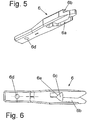
- the coupling member 6 is, which in particular the FIGS. 5 and 6 make clear, provided with a first slide guide 6a and a second slide guide 6b, wherein the two sliding guides 6a and 6b are arranged in mirror image to each other and extend substantially V-shaped spread apart.
- the two slotted guides 6a and 6b are arranged within the coupling member 6 in different planes.
- the depth of the slide guides 6a and 6b is slightly larger than the total thickness of the coupling member 6, so that there is an opening 6c in the overlap region of the two slide guides 6a and 6b.
- the coupling member 6 At its end facing away from the slide guides 6a and 6b, the coupling member 6 is equipped with a bearing bore 6d.
- This bearing bore 6d will pass through a bearing pin 9, which is connected to a fixedly mounted on the center rail 4 bearing block 10.
- the axis of the bearing pin 9 extends perpendicular to the displacement plane of the entire telescopic guide rail 1.
- the coupling member 6 is mounted pivotally within limits.
- the attached to the carcass rail 2 first sliding block 7 is assigned to the corresponding downwardly facing first slide guide 6a.
- the coupling member 6 is then pivoted about the axis of the bearing pin 7, whereby a release of the blockage between the located on the running rail 3 sliding block 8 and the coupling member 6 and simultaneously causes a block between the attached to the carcass rail 2 sliding block 7 and the coupling member 6 becomes.
- the running rail 3 can be separated from the center rail 4 and pulled completely opposite to this, while at the same time the middle rail 4 is secured or blocked against pushing back relative to the carcass rail 2.
- the coupling member 6 is a total of one piece made of plastic. Due to the opening 6c in the transition region between the two slotted guides 6a and 6b here is a certain spring elasticity achieved by the noise during the "switching" between the individual coupling states described above, can be largely damped. In addition, in the storage area of the coupling member 6, a damping spring (not shown) is provided be, which can also take care of the noise attenuation when switching the coupling member 6 care.
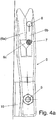
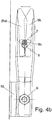
- FIGS. 4a to 4d show again in a schematic representation of the sequence of switching of the coupling member 6 through the two sliding blocks 7 and 8.
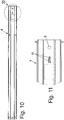
- FIGS. 10 to 12 show, the center rail 4, on which the coupling member 6 is pivotally mounted, with two mutually angled forms 11, which is associated with a corresponding recess 12 of the coupling member 6.
- the forms 11 and the recess 12 are arranged so that the coupling member 6 is secured in both possible end positions during pivoting against unintentional leaving this pivot position, that is, the coupling member 6 can not fall out of gravity by gravity from one of the pivoting positions. This opens up the possibility of using a telescopic guide rail according to FIGS. 7 to 11 without any modification both on the left and on the right side of a furniture pull-out.
- the characteristics 11 may also be provided on the coupling member 6 and accordingly the corresponding recesses may be provided on the center rail 4.
- the corresponding recesses may be provided on the center rail 4.
- Magnetic regions can also be provided for this purpose on the named components.
- the coupling member 6 which in turn is made entirely of a plastic, in the region of its bearing bore 6d provided with an opening 13 within which spring-like webs 14 are arranged, which carry the central region 15 with the bearing bore 6d.
- this central portion 15 of the coupling member 6 having the bearing bore 6d can be sprung to a certain extent in the direction of displacement and thus damped.
- the coupling member 6 is mounted on the side of the middle rail 4 facing the running rail 3.
- the attached to the carcass rail 2 sliding block 7 can interact properly with the coupling member 6, in the region of the center rail 4 is an opening 16 is provided through which engages the at least the sliding block 7 associated with the corresponding region of the control cam of the coupling member 6.
- sliding plane of the telescopic guide rail 1 has been used repeatedly. This is understood to mean a horizontal plane in the use position within which a furniture drawer mounted on two telescopic guide rails according to the invention is moved.
Landscapes
- Drawers Of Furniture (AREA)
Claims (10)
- Rail de guidage télescopique (1) destiné à des éléments de meuble déployables tels que des tiroirs ou similaires comprenant un rail de corps (2) pouvant être fixé à un corps de meuble, un rail de roulement (3) pouvant être relié à un élément de meuble déployable et un rail médian (4) prolongeant le déploiement monté entre le rail de corps (2) et le rail de roulement (3) ainsi qu'une commande d'actionnement (5) au moyen de laquelle, lors de son déploiement à partir de la position de fermeture, le rail de roulement (3) est couplé au rail médian (4) jusqu'à ce que ce rail médian (4) ait atteint sa position de déploiement maximum, et est bloqué par rapport au rail de corps (2) dans cette position en étant simultanément découplé du rail médian (4), et le rail médian (4) ne peut être déplacé à nouveau dans la direction de fermeture, par rapport au rail de corps (2) que lorsque le rail de roulement (3) a été déplacé au maximum dans la direction de repliement par rapport au rail médian (4) préalablement bloqué, et est alors à nouveau couplé au rail médian,
caractérisé en ce que
la commande d'actionnement (5) est constituée par un organe d'accouplement (6) équipé de deux guides de coulisse (6a, 6b) s'étendant symétriquement l'un par rapport à l'autre, ainsi que par un premier coulisseau (7) fixé au rail de corps (2) et associé à un premier guide de coulisse (6a) et par un second coulisseau (8) fixé au rail de roulement (3) et associé au second guide de coulisse (6b), l'organe d'accouplement (6) étant monté pivotant autour d'un axe (9) s'étendant perpendiculairement au plan de coulissement du rail de guidage télescopique (1) s'étendant horizontalement dans la position d'utilisation, et, les guides de coulisse (6a, 6b) s'étendant en s'écartant en forme de V l'un par rapport à l'autre de façon à provoquer, lors de l'introduction du premier coulisseau (7) dans le premier guide de coulisse (6a) qui lui est associé, une commutation de l'organe d'accouplement (6) et une libération liée à celle-ci du second coulisseau (8) du second guide de coulisse (6b) qui lui est associé et inversement. - Rail de guidage télescopique conforme à la revendication 1,
caractérisé en ce que
les coulisseaux (7, 8) sont positionnés l'un sur l'autre sur le rail de corps (2) ou sur le rail de roulement (3), et, de manière correspondante, les guides de coulisse (6a, 6b) sont positionnés sur l'organe d'accouplement (6) dans différents plans en hauteur de cet organe d'accouplement (6). - Rail de guidage télescopique conforme à la revendication 2,
caractérisé en ce que
la profondeur du premier guide de coulisse (6a) qui est ouvert vers le bas en direction du rail de corps (2) et la profondeur du second guide de coulisse (6b) qui est ouvert vers le haut dans la direction du rail de roulement (3) est respectivement supérieure à la moitié de l'épaisseur totale de l'organe d'accouplement (6), de sorte que, dans la zone de chevauchement des deux guides de coulisse (6a, 6b), un évidement (6c) soit formé dans la zone de la pointe de leur extension en forme de V. - Rail de guidage télescopique conforme à l'une des revendications précédentes,
caractérisé en ce que
l'organe d'accouplement (6) est globalement réalisé en une seule pièce en un matériau synthétique. - Rail de guidage télescopique conforme à l'une des revendications précédentes,
caractérisé en ce que
l'organe d'accouplement (6) est monté pivotant autour de l'axe d'un tourillon de palier (9), ce tourillon de palier (9) étant porté par un sabot d'appui (10) fixé au rail médian (4). - Rail de guidage télescopique conforme à la revendication 1,
caractérisé en ce que
des moyens d'amortissement du bruit provoqué lors de la commutation de l'organe d'accouplement (6) sont situés dans la zone de montage de l'organe d'accouplement (6). - Rail de guidage télescopique conforme à la revendication 6,
caractérisé en ce que
les moyens d'amortissement sont constitués par un ou plusieurs ressorts. - Rail de guidage télescopique (1) destiné à des éléments de meuble déployables tels que des tiroirs ou similaires comprenant un rail de corps (2) pouvant être fixé à un corps de meuble, un rail de roulement (3) pouvant être relié à un élément de meuble déployable, et un rail médian (4) prolongeant le déploiement monté entre le rail de corps (2) et le rail de roulement (3), ainsi qu'une commande d'actionnement (5) au moyen de laquelle, lors de son déploiement à partir de la position de fermeture, le rail de roulement (3) est couplé au rail médian (4) jusqu'à ce que ce rail médian (4) ait atteint sa position de déploiement maximum, et est bloqué par rapport au rail de corps (2), dans cette position en étant simultanément découplé du rail médian (4), et, le rail médian (4) ne peut être à nouveau déplacé dans la direction de fermeture par rapport au rail de corps (2) que lorsque le rail de roulement (3) a été déplacé au maximum dans la direction de repliement par rapport au rail médian (4) préalablement bloqué et est alors à nouveau couplé au rail médian (4),
caractérisé en ce que
la commande d'actionnement (5) est constituée par un organe d'accouplement (6) équipé de deux guides de coulisse (6a, 6b) s'étendant symétriquement l'un par rapport à l'autre, ainsi que par un premier coulisseau (7) fixé au rail de corps (2) et associé à un premier guide de coulisse (6a) et par un second coulisseau (8) fixé au rail de roulement (3) et associé au second guide de coulisse (6b), l'organe d'accouplement (6) étant monté pivotant autour d'un axe (9) s'étendant parallèlement au plan de coulissement du rail de guidage télescopique (1) s'étendant horizontalement dans la position d'utilisation, et les guides de coulisse (6a, 6b) s'étendant en s'écartant en forme de V l'un par rapport à l'autre de façon à provoquer, lors de l'introduction du premier coulisseau (7), dans le premier guide de coulisse (6a) qui lui est associé une commutation de l'organe d'accouplement (6) et une libération liée à celle-ci du second coulisseau (8) du second guide de coulisse (6b) qui lui est associé et inversement. - Rail de guidage télescopique conforme à l'une des revendications précédents,
caractérisé en ce que
le rail médian (4) est équipé de bossages (11) s'étendant angulairement et l'organe d'accouplement (6) est équipé d'un évidement (12) associé à ces bossages (11), l'un des bossages (11) venant respectivement en prise dans l'évidement (12) de l'organe d'accouplement (6) lorsque cet organe d'accouplement (6) est déplacé par pivotement dans l'une de ses positions de commutation possibles. - Rail de guidage télescopique conforme à l'une des revendications précédentes,
caractérisé en ce que
l'organe d'accouplement (6) est équipé dans la zone voisine de son perçage de montage (6d) d'un évidement (13) à la partie interne duquel des tiges élastiques (14) s'appuient élastiquement sur une zone centrale (15) comprenant le perçage de montage (6d).
Applications Claiming Priority (3)
| Application Number | Priority Date | Filing Date | Title |
|---|---|---|---|
| DE202007006692 | 2007-05-07 | ||
| DE202008004597U DE202008004597U1 (de) | 2007-05-07 | 2008-04-02 | Teleskopführungsschiene |
| PCT/EP2008/055157 WO2008135425A1 (fr) | 2007-05-07 | 2008-04-28 | Rail de guidage télescopique |
Publications (2)
| Publication Number | Publication Date |
|---|---|
| EP2144530A1 EP2144530A1 (fr) | 2010-01-20 |
| EP2144530B1 true EP2144530B1 (fr) | 2017-06-21 |
Family
ID=39768321
Family Applications (1)
| Application Number | Title | Priority Date | Filing Date |
|---|---|---|---|
| EP08759387.7A Not-in-force EP2144530B1 (fr) | 2007-05-07 | 2008-04-28 | Rail de guidage télescopique |
Country Status (5)
| Country | Link |
|---|---|
| EP (1) | EP2144530B1 (fr) |
| CN (1) | CN101720192B (fr) |
| DE (1) | DE202008004597U1 (fr) |
| ES (1) | ES2640977T3 (fr) |
| WO (1) | WO2008135425A1 (fr) |
Cited By (2)
| Publication number | Priority date | Publication date | Assignee | Title |
|---|---|---|---|---|
| DE102017120181A1 (de) | 2017-09-01 | 2019-03-07 | Paul Hettich Gmbh & Co. Kg | Auszugsführung |
| US12628306B2 (en) | 2022-09-22 | 2026-05-12 | Asia Pacific CIS (Wuxi) Co. Ltd. | Double unlocking mechanism for slide rails |
Families Citing this family (9)
| Publication number | Priority date | Publication date | Assignee | Title |
|---|---|---|---|---|
| DE202010011853U1 (de) * | 2010-08-25 | 2011-11-28 | Grass Gmbh | Führungseinheit zur Führung eines relativ zu einem Möbelkorpus beweglichen Möbelauszugs, zum Beispiel einer Schublade |
| CN103126354B (zh) * | 2013-03-23 | 2015-06-03 | 伍志勇 | 轮式抽屉滑轨的减噪机构 |
| DE102013113672A1 (de) * | 2013-06-14 | 2014-12-18 | Paul Hettich Gmbh & Co. Kg | Auszugssystem |
| DE102017115952A1 (de) | 2017-07-14 | 2019-01-17 | Paul Hettich Gmbh & Co. Kg | Schiebe- und Hubmechanismus für ein Möbel oder Haushaltsgerät und Möbel oder Haushaltsgerät mit einem derartigen Schiebe- und Hubmechanismus |
| CN108035121B (zh) * | 2018-01-04 | 2024-01-05 | 南京贝奇工业设计有限公司 | 一种用于洗衣机的自动抽屉盒及其控制方法 |
| CA3039711A1 (fr) * | 2018-04-06 | 2019-10-06 | Belden Canada Inc. | Systeme et plateau a connexion croisee |
| JP6962568B2 (ja) * | 2018-05-29 | 2021-11-05 | 日本アキュライド株式会社 | 伸縮順序機構付きスライドレール |
| DE102018118973A1 (de) * | 2018-08-03 | 2020-02-06 | Liebherr-Verzahntechnik Gmbh | Teleskopschiene |
| DE202018106058U1 (de) * | 2018-10-23 | 2020-01-24 | Accuride International Gmbh | Teleskopschiene |
Family Cites Families (3)
| Publication number | Priority date | Publication date | Assignee | Title |
|---|---|---|---|---|
| EP0620993A1 (fr) * | 1993-04-23 | 1994-10-26 | Alfit Aktiengesellschaft | Tiroir à glissière double |
| AT406330B (de) * | 1996-01-16 | 2000-04-25 | Blum Gmbh Julius | Ausziehführung für eine schublade |
| CN2642137Y (zh) * | 2003-04-30 | 2004-09-22 | 南俊国际股份有限公司 | 增加使用寿命及可延长伸展长度的抽屉滑轨构造 |
-
2008
- 2008-04-02 DE DE202008004597U patent/DE202008004597U1/de not_active Expired - Lifetime
- 2008-04-28 WO PCT/EP2008/055157 patent/WO2008135425A1/fr not_active Ceased
- 2008-04-28 ES ES08759387.7T patent/ES2640977T3/es active Active
- 2008-04-28 CN CN200880015068XA patent/CN101720192B/zh not_active Expired - Fee Related
- 2008-04-28 EP EP08759387.7A patent/EP2144530B1/fr not_active Not-in-force
Non-Patent Citations (1)
| Title |
|---|
| None * |
Cited By (4)
| Publication number | Priority date | Publication date | Assignee | Title |
|---|---|---|---|---|
| DE102017120181A1 (de) | 2017-09-01 | 2019-03-07 | Paul Hettich Gmbh & Co. Kg | Auszugsführung |
| WO2019042980A1 (fr) | 2017-09-01 | 2019-03-07 | Paul Hettich Gmbh & Co. Kg | Glissière |
| DE102017120181B4 (de) | 2017-09-01 | 2026-03-05 | Paul Hettich Gmbh & Co. Kg | Auszugsführung |
| US12628306B2 (en) | 2022-09-22 | 2026-05-12 | Asia Pacific CIS (Wuxi) Co. Ltd. | Double unlocking mechanism for slide rails |
Also Published As
| Publication number | Publication date |
|---|---|
| CN101720192A (zh) | 2010-06-02 |
| EP2144530A1 (fr) | 2010-01-20 |
| DE202008004597U1 (de) | 2008-09-18 |
| ES2640977T3 (es) | 2017-11-07 |
| WO2008135425A1 (fr) | 2008-11-13 |
| CN101720192B (zh) | 2011-12-21 |
Similar Documents
| Publication | Publication Date | Title |
|---|---|---|
| EP2144530A1 (fr) | Rail de guidage télescopique | |
| AT509540B1 (de) | Ausziehführung für schubladen | |
| EP2916688B1 (fr) | Glissière télescopique de tiroir | |
| DE112009000174B4 (de) | Gleitführungen für Schubladensysteme und Verschlussmechaniken | |
| AT506062B1 (de) | Rollen-ausziehführung | |
| AT521133B1 (de) | Führungssystem zur Führung eines bewegbar gelagerten Türflügels | |
| DE202005004336U1 (de) | Selbsteinzugsvorrichtung für bewegliche Möbelteile | |
| DE202008016409U1 (de) | Selbsteinzugsvorrichtung und Auszugsführung | |
| AT513856B1 (de) | Selbsteinzugsvorrichtung für ein verschiebbares Möbelteil | |
| EP3838069A1 (fr) | Guidage d'extension de tiroir | |
| WO2019033136A1 (fr) | Glissière télescopique pour tiroir | |
| EP0957714B1 (fr) | Coulisse encastree de guidage de sortie pour tiroirs etc. | |
| WO2006106029A1 (fr) | Glissiere telescopique destinee a un element de meuble dispose de façon mobile dans un corps de meuble | |
| AT517479B1 (de) | Schubladenausziehführung | |
| EP1384420B1 (fr) | Mécanisme de fermeture automatique amorti | |
| EP2716182B1 (fr) | Guidage d'extraction pour un élément de meuble pouvant être extrait d'un corps de meuble | |
| AT520805A1 (de) | Ausziehführung | |
| WO2024231439A1 (fr) | Glissière de tiroir | |
| EP1103690A1 (fr) | Exutoire de désenfumage | |
| EP4003095B1 (fr) | Guide d'extraction de tiroir | |
| AT406109B (de) | Ausziehführungsgarnitur für schubladen | |
| EP1721547B1 (fr) | Guide lateral pour un élément d'extraction d'un tiroir vertical | |
| DE202004007227U1 (de) | Schubladenführung | |
| DE4327688A1 (de) | Auszugführung | |
| DE20318735U1 (de) | Teleskopführungsschiene für Möbelauszüge wie Schubkästen o.dgl. |
Legal Events
| Date | Code | Title | Description |
|---|---|---|---|
| PUAI | Public reference made under article 153(3) epc to a published international application that has entered the european phase |
Free format text: ORIGINAL CODE: 0009012 |
|
| 17P | Request for examination filed |
Effective date: 20091023 |
|
| AK | Designated contracting states |
Kind code of ref document: A1 Designated state(s): AT BE BG CH CY CZ DE DK EE ES FI FR GB GR HR HU IE IS IT LI LT LU LV MC MT NL NO PL PT RO SE SI SK TR |
|
| AX | Request for extension of the european patent |
Extension state: AL BA MK RS |
|
| DAX | Request for extension of the european patent (deleted) | ||
| REG | Reference to a national code |
Ref country code: DE Ref legal event code: R079 Ref document number: 502008015411 Country of ref document: DE Free format text: PREVIOUS MAIN CLASS: A47B0088100000 Ipc: A47B0088493000 |
|
| GRAP | Despatch of communication of intention to grant a patent |
Free format text: ORIGINAL CODE: EPIDOSNIGR1 |
|
| RIC1 | Information provided on ipc code assigned before grant |
Ipc: A47B 88/493 20170101AFI20170120BHEP |
|
| INTG | Intention to grant announced |
Effective date: 20170210 |
|
| GRAS | Grant fee paid |
Free format text: ORIGINAL CODE: EPIDOSNIGR3 |
|
| GRAA | (expected) grant |
Free format text: ORIGINAL CODE: 0009210 |
|
| AK | Designated contracting states |
Kind code of ref document: B1 Designated state(s): AT BE BG CH CY CZ DE DK EE ES FI FR GB GR HR HU IE IS IT LI LT LU LV MC MT NL NO PL PT RO SE SI SK TR |
|
| REG | Reference to a national code |
Ref country code: GB Ref legal event code: FG4D Free format text: NOT ENGLISH |
|
| REG | Reference to a national code |
Ref country code: CH Ref legal event code: EP |
|
| REG | Reference to a national code |
Ref country code: IE Ref legal event code: FG4D Free format text: LANGUAGE OF EP DOCUMENT: GERMAN |
|
| REG | Reference to a national code |
Ref country code: AT Ref legal event code: REF Ref document number: 902156 Country of ref document: AT Kind code of ref document: T Effective date: 20170715 |
|
| REG | Reference to a national code |
Ref country code: DE Ref legal event code: R096 Ref document number: 502008015411 Country of ref document: DE |
|
| REG | Reference to a national code |
Ref country code: SE Ref legal event code: TRGR |
|
| REG | Reference to a national code |
Ref country code: NL Ref legal event code: MP Effective date: 20170621 |
|
| PG25 | Lapsed in a contracting state [announced via postgrant information from national office to epo] |
Ref country code: HR Free format text: LAPSE BECAUSE OF FAILURE TO SUBMIT A TRANSLATION OF THE DESCRIPTION OR TO PAY THE FEE WITHIN THE PRESCRIBED TIME-LIMIT Effective date: 20170621 Ref country code: FI Free format text: LAPSE BECAUSE OF FAILURE TO SUBMIT A TRANSLATION OF THE DESCRIPTION OR TO PAY THE FEE WITHIN THE PRESCRIBED TIME-LIMIT Effective date: 20170621 Ref country code: NO Free format text: LAPSE BECAUSE OF FAILURE TO SUBMIT A TRANSLATION OF THE DESCRIPTION OR TO PAY THE FEE WITHIN THE PRESCRIBED TIME-LIMIT Effective date: 20170921 Ref country code: GR Free format text: LAPSE BECAUSE OF FAILURE TO SUBMIT A TRANSLATION OF THE DESCRIPTION OR TO PAY THE FEE WITHIN THE PRESCRIBED TIME-LIMIT Effective date: 20170922 Ref country code: LT Free format text: LAPSE BECAUSE OF FAILURE TO SUBMIT A TRANSLATION OF THE DESCRIPTION OR TO PAY THE FEE WITHIN THE PRESCRIBED TIME-LIMIT Effective date: 20170621 |
|
| REG | Reference to a national code |
Ref country code: ES Ref legal event code: FG2A Ref document number: 2640977 Country of ref document: ES Kind code of ref document: T3 Effective date: 20171107 |
|
| REG | Reference to a national code |
Ref country code: LT Ref legal event code: MG4D |
|
| PG25 | Lapsed in a contracting state [announced via postgrant information from national office to epo] |
Ref country code: LV Free format text: LAPSE BECAUSE OF FAILURE TO SUBMIT A TRANSLATION OF THE DESCRIPTION OR TO PAY THE FEE WITHIN THE PRESCRIBED TIME-LIMIT Effective date: 20170621 Ref country code: NL Free format text: LAPSE BECAUSE OF FAILURE TO SUBMIT A TRANSLATION OF THE DESCRIPTION OR TO PAY THE FEE WITHIN THE PRESCRIBED TIME-LIMIT Effective date: 20170621 Ref country code: BG Free format text: LAPSE BECAUSE OF FAILURE TO SUBMIT A TRANSLATION OF THE DESCRIPTION OR TO PAY THE FEE WITHIN THE PRESCRIBED TIME-LIMIT Effective date: 20170921 |
|
| PG25 | Lapsed in a contracting state [announced via postgrant information from national office to epo] |
Ref country code: RO Free format text: LAPSE BECAUSE OF FAILURE TO SUBMIT A TRANSLATION OF THE DESCRIPTION OR TO PAY THE FEE WITHIN THE PRESCRIBED TIME-LIMIT Effective date: 20170621 Ref country code: CZ Free format text: LAPSE BECAUSE OF FAILURE TO SUBMIT A TRANSLATION OF THE DESCRIPTION OR TO PAY THE FEE WITHIN THE PRESCRIBED TIME-LIMIT Effective date: 20170621 Ref country code: EE Free format text: LAPSE BECAUSE OF FAILURE TO SUBMIT A TRANSLATION OF THE DESCRIPTION OR TO PAY THE FEE WITHIN THE PRESCRIBED TIME-LIMIT Effective date: 20170621 Ref country code: SK Free format text: LAPSE BECAUSE OF FAILURE TO SUBMIT A TRANSLATION OF THE DESCRIPTION OR TO PAY THE FEE WITHIN THE PRESCRIBED TIME-LIMIT Effective date: 20170621 |
|
| PG25 | Lapsed in a contracting state [announced via postgrant information from national office to epo] |
Ref country code: PL Free format text: LAPSE BECAUSE OF FAILURE TO SUBMIT A TRANSLATION OF THE DESCRIPTION OR TO PAY THE FEE WITHIN THE PRESCRIBED TIME-LIMIT Effective date: 20170621 Ref country code: IS Free format text: LAPSE BECAUSE OF FAILURE TO SUBMIT A TRANSLATION OF THE DESCRIPTION OR TO PAY THE FEE WITHIN THE PRESCRIBED TIME-LIMIT Effective date: 20171021 |
|
| REG | Reference to a national code |
Ref country code: DE Ref legal event code: R097 Ref document number: 502008015411 Country of ref document: DE |
|
| PLBE | No opposition filed within time limit |
Free format text: ORIGINAL CODE: 0009261 |
|
| STAA | Information on the status of an ep patent application or granted ep patent |
Free format text: STATUS: NO OPPOSITION FILED WITHIN TIME LIMIT |
|
| PG25 | Lapsed in a contracting state [announced via postgrant information from national office to epo] |
Ref country code: DK Free format text: LAPSE BECAUSE OF FAILURE TO SUBMIT A TRANSLATION OF THE DESCRIPTION OR TO PAY THE FEE WITHIN THE PRESCRIBED TIME-LIMIT Effective date: 20170621 |
|
| 26N | No opposition filed |
Effective date: 20180322 |
|
| PG25 | Lapsed in a contracting state [announced via postgrant information from national office to epo] |
Ref country code: SI Free format text: LAPSE BECAUSE OF FAILURE TO SUBMIT A TRANSLATION OF THE DESCRIPTION OR TO PAY THE FEE WITHIN THE PRESCRIBED TIME-LIMIT Effective date: 20170621 |
|
| PG25 | Lapsed in a contracting state [announced via postgrant information from national office to epo] |
Ref country code: MT Free format text: LAPSE BECAUSE OF FAILURE TO SUBMIT A TRANSLATION OF THE DESCRIPTION OR TO PAY THE FEE WITHIN THE PRESCRIBED TIME-LIMIT Effective date: 20170621 |
|
| PG25 | Lapsed in a contracting state [announced via postgrant information from national office to epo] |
Ref country code: MC Free format text: LAPSE BECAUSE OF FAILURE TO SUBMIT A TRANSLATION OF THE DESCRIPTION OR TO PAY THE FEE WITHIN THE PRESCRIBED TIME-LIMIT Effective date: 20170621 |
|
| REG | Reference to a national code |
Ref country code: CH Ref legal event code: PL |
|
| REG | Reference to a national code |
Ref country code: SE Ref legal event code: EUG |
|
| REG | Reference to a national code |
Ref country code: BE Ref legal event code: MM Effective date: 20180430 |
|
| GBPC | Gb: european patent ceased through non-payment of renewal fee |
Effective date: 20180428 |
|
| REG | Reference to a national code |
Ref country code: IE Ref legal event code: MM4A |
|
| PG25 | Lapsed in a contracting state [announced via postgrant information from national office to epo] |
Ref country code: LU Free format text: LAPSE BECAUSE OF NON-PAYMENT OF DUE FEES Effective date: 20180428 Ref country code: SE Free format text: LAPSE BECAUSE OF NON-PAYMENT OF DUE FEES Effective date: 20180429 |
|
| PG25 | Lapsed in a contracting state [announced via postgrant information from national office to epo] |
Ref country code: BE Free format text: LAPSE BECAUSE OF NON-PAYMENT OF DUE FEES Effective date: 20180430 Ref country code: GB Free format text: LAPSE BECAUSE OF NON-PAYMENT OF DUE FEES Effective date: 20180428 Ref country code: CH Free format text: LAPSE BECAUSE OF NON-PAYMENT OF DUE FEES Effective date: 20180430 Ref country code: LI Free format text: LAPSE BECAUSE OF NON-PAYMENT OF DUE FEES Effective date: 20180430 |
|
| PG25 | Lapsed in a contracting state [announced via postgrant information from national office to epo] |
Ref country code: FR Free format text: LAPSE BECAUSE OF NON-PAYMENT OF DUE FEES Effective date: 20180430 Ref country code: IE Free format text: LAPSE BECAUSE OF NON-PAYMENT OF DUE FEES Effective date: 20180428 Ref country code: IT Free format text: LAPSE BECAUSE OF NON-PAYMENT OF DUE FEES Effective date: 20180428 |
|
| REG | Reference to a national code |
Ref country code: AT Ref legal event code: MM01 Ref document number: 902156 Country of ref document: AT Kind code of ref document: T Effective date: 20180428 |
|
| REG | Reference to a national code |
Ref country code: ES Ref legal event code: FD2A Effective date: 20190912 |
|
| PG25 | Lapsed in a contracting state [announced via postgrant information from national office to epo] |
Ref country code: ES Free format text: LAPSE BECAUSE OF NON-PAYMENT OF DUE FEES Effective date: 20180429 Ref country code: AT Free format text: LAPSE BECAUSE OF NON-PAYMENT OF DUE FEES Effective date: 20180428 |
|
| PG25 | Lapsed in a contracting state [announced via postgrant information from national office to epo] |
Ref country code: TR Free format text: LAPSE BECAUSE OF FAILURE TO SUBMIT A TRANSLATION OF THE DESCRIPTION OR TO PAY THE FEE WITHIN THE PRESCRIBED TIME-LIMIT Effective date: 20170621 |
|
| PG25 | Lapsed in a contracting state [announced via postgrant information from national office to epo] |
Ref country code: PT Free format text: LAPSE BECAUSE OF FAILURE TO SUBMIT A TRANSLATION OF THE DESCRIPTION OR TO PAY THE FEE WITHIN THE PRESCRIBED TIME-LIMIT Effective date: 20170621 Ref country code: HU Free format text: LAPSE BECAUSE OF FAILURE TO SUBMIT A TRANSLATION OF THE DESCRIPTION OR TO PAY THE FEE WITHIN THE PRESCRIBED TIME-LIMIT; INVALID AB INITIO Effective date: 20080428 |
|
| PG25 | Lapsed in a contracting state [announced via postgrant information from national office to epo] |
Ref country code: CY Free format text: LAPSE BECAUSE OF FAILURE TO SUBMIT A TRANSLATION OF THE DESCRIPTION OR TO PAY THE FEE WITHIN THE PRESCRIBED TIME-LIMIT Effective date: 20170621 |
|
| PGFP | Annual fee paid to national office [announced via postgrant information from national office to epo] |
Ref country code: DE Payment date: 20210421 Year of fee payment: 14 |
|
| REG | Reference to a national code |
Ref country code: DE Ref legal event code: R119 Ref document number: 502008015411 Country of ref document: DE |
|
| PG25 | Lapsed in a contracting state [announced via postgrant information from national office to epo] |
Ref country code: DE Free format text: LAPSE BECAUSE OF NON-PAYMENT OF DUE FEES Effective date: 20221103 |