EP2145123B1 - Mechanische verschlussvorrichtung und pumpe - Google Patents
Mechanische verschlussvorrichtung und pumpe Download PDFInfo
- Publication number
- EP2145123B1 EP2145123B1 EP08767137.6A EP08767137A EP2145123B1 EP 2145123 B1 EP2145123 B1 EP 2145123B1 EP 08767137 A EP08767137 A EP 08767137A EP 2145123 B1 EP2145123 B1 EP 2145123B1
- Authority
- EP
- European Patent Office
- Prior art keywords
- sealing device
- seal
- mechanical sealing
- outer peripheral
- peripheral surface
- Prior art date
- Legal status (The legal status is an assumption and is not a legal conclusion. Google has not performed a legal analysis and makes no representation as to the accuracy of the status listed.)
- Active
Links
Images


Classifications
-
- F—MECHANICAL ENGINEERING; LIGHTING; HEATING; WEAPONS; BLASTING
- F16—ENGINEERING ELEMENTS AND UNITS; GENERAL MEASURES FOR PRODUCING AND MAINTAINING EFFECTIVE FUNCTIONING OF MACHINES OR INSTALLATIONS; THERMAL INSULATION IN GENERAL
- F16J—PISTONS; CYLINDERS; SEALINGS
- F16J15/00—Sealings
- F16J15/16—Sealings between relatively-moving surfaces
- F16J15/34—Sealings between relatively-moving surfaces with slip-ring pressed against a more or less radial face on one member
- F16J15/38—Sealings between relatively-moving surfaces with slip-ring pressed against a more or less radial face on one member sealed by a packing
-
- F—MECHANICAL ENGINEERING; LIGHTING; HEATING; WEAPONS; BLASTING
- F04—POSITIVE - DISPLACEMENT MACHINES FOR LIQUIDS; PUMPS FOR LIQUIDS OR ELASTIC FLUIDS
- F04D—NON-POSITIVE-DISPLACEMENT PUMPS
- F04D29/00—Details, component parts, or accessories
- F04D29/08—Sealings
- F04D29/10—Shaft sealings
- F04D29/12—Shaft sealings using sealing-rings
- F04D29/126—Shaft sealings using sealing-rings especially adapted for liquid pumps
-
- F—MECHANICAL ENGINEERING; LIGHTING; HEATING; WEAPONS; BLASTING
- F16—ENGINEERING ELEMENTS AND UNITS; GENERAL MEASURES FOR PRODUCING AND MAINTAINING EFFECTIVE FUNCTIONING OF MACHINES OR INSTALLATIONS; THERMAL INSULATION IN GENERAL
- F16J—PISTONS; CYLINDERS; SEALINGS
- F16J15/00—Sealings
- F16J15/16—Sealings between relatively-moving surfaces
- F16J15/34—Sealings between relatively-moving surfaces with slip-ring pressed against a more or less radial face on one member
- F16J15/3464—Mounting of the seal
- F16J15/3468—Means for controlling the deformations of the contacting faces
-
- F—MECHANICAL ENGINEERING; LIGHTING; HEATING; WEAPONS; BLASTING
- F16—ENGINEERING ELEMENTS AND UNITS; GENERAL MEASURES FOR PRODUCING AND MAINTAINING EFFECTIVE FUNCTIONING OF MACHINES OR INSTALLATIONS; THERMAL INSULATION IN GENERAL
- F16J—PISTONS; CYLINDERS; SEALINGS
- F16J15/00—Sealings
- F16J15/16—Sealings between relatively-moving surfaces
- F16J15/34—Sealings between relatively-moving surfaces with slip-ring pressed against a more or less radial face on one member
- F16J15/3464—Mounting of the seal
- F16J15/3472—Means for centering or aligning the contacting faces
-
- F—MECHANICAL ENGINEERING; LIGHTING; HEATING; WEAPONS; BLASTING
- F16—ENGINEERING ELEMENTS AND UNITS; GENERAL MEASURES FOR PRODUCING AND MAINTAINING EFFECTIVE FUNCTIONING OF MACHINES OR INSTALLATIONS; THERMAL INSULATION IN GENERAL
- F16J—PISTONS; CYLINDERS; SEALINGS
- F16J15/00—Sealings
- F16J15/16—Sealings between relatively-moving surfaces
- F16J15/34—Sealings between relatively-moving surfaces with slip-ring pressed against a more or less radial face on one member
- F16J15/3464—Mounting of the seal
- F16J15/3476—Means for minimising vibrations of the slip-ring
Definitions
- the present invention refers generally to mechanical sealing devices, including or forming a part of equipment comprising a rotating shaft extending through a passage to be sealed. More specifically, the present invention refers to a mechanical sealing device according to the preamble of claim 1, and to a pump according to the preamble of claim 13.
- Such a mechanical sealing device can be used in a variety of applications.
- such a mechanical sealing device can be used in pumps for pumping a liquid.
- the first holder element may then be joined to the pump housing via a peripheral thread provided radially outside the first seal element.
- possible stresses in the pump housing can be transferred to the first seal surface via the thread, and thus create non planar states and consequently leakage.
- US-A-3,291,493 discloses a mechanical sealing device comprising a first machine part and a second machine part. A first sealing ring is connected to the first machine part, and a second sealing ring is connected to the second machine part. The second sealing ring is surrounded by a gasket element extending around an inner corner of the sealing ring.
- US-A-5,758,880 discloses a mechanical sealing device incorporating a similar solution, where a ceramic sealing element is supported by an elastomer element extending around a corner of the sealing element.
- EP-A-798499 discloses a further mechanical sealing device, which comprises a rotary seal element mounted on a shaft, and an opposite stationary seal element supported by a holder component via an elastomer ring.
- the elastomer ring extends also in this case around an inner corner of the stationary seal element.
- GB-A-2044862 discloses a mechanical sealing device with a rotating seal element and an opposite stationary seal element supported in a housing via an O-ring.
- GB 762950 discloses a mechanical sealing device according to the preamble of claim 1.
- the object of the present invention is to remedy the problems discussed above. Especially, it is aimed at a mechanical sealing device, which prevents stresses from the connection between the holder element and a housing to be transferred to the seal surface, and which avoids contact between an elastomer element and the medium to be sealed.
- the mechanical sealing device initially defined, which is characterized in that the elastomer element comprises an annular flange extending inwardly into the groove and that the first holder element comprises locking means adapted to secure the elastomer element between the outer peripheral surface and the inner surface.
- any medium to be sealed is efficiently prevented form reaching the elastomer element provided radially outside the abutment area between the opposite backing surface of the first seal element and the support surface of the first holder element.
- the elastomer element permits the first seal element to perform slight movements along a radial plane, so that any possible transfer of stresses from the connection of the first holder element to any component, for instance an external component such as a housing, may be reduced or prevented.
- the outer peripheral surface and the inner surface are concentric with the axis of rotation.
- the opposite backing surface and the support surface extends in a radial plane with respect to the axis of rotation.
- the abutment between the backing surface and the support surface can be made very tight so that no media may pass through the abutment area.
- the first seal element comprises a surrounding groove
- the elastomer element comprises an annular flange extending inwardly into the groove.
- an annular flange of the elastomer element will thus be engaged in the surrounding groove so that the elastomer element is securely held between the outer peripheral surface of the first seal element and the inner surface of the first holder element during operation of the mechanical sealing device.
- the surrounding groove extends inwardly from the outer peripheral surface.
- the surrounding groove may be provided anywhere on the outer peripheral surface.
- the surrounding groove is disposed at a corner formed between the opposite backing surface and the outer peripheral surface.
- the first holder element comprises locking means adapted to secure the elastomer element between the outer peripheral surface and the inner surface, and to secure the backing surface tightly against the support surface.
- locking means can be provided as an alternative or a supplement to the surrounding flange and the annular groove.
- the locking means may comprise a locking flange projecting axially from the inner surface and being bent towards the outer peripheral surface. By such a bent flange, the elastomer element will be pressed against the outer peripheral surface of the first seal element and thus be securely held in the desired position.
- the outer peripheral surface of the first seal element may have an inclined surface portion tapering towards the first seal surface, wherein the locking flange may be provided opposite and outside the inclined surface portion.
- the first and second seal elements are manufactured in a material selected from the group comprising a metallic material, a ceramic material, a carbide material and a nitride material.
- the first holder element is manufactured in a rigid, non-elastic material.
- the first holder element is engaged in a housing by means of a thread engagement.
- the object is also achieved by means of the pump initially defined, which is characterized in that the opposite backing surface of the first seal element abuts tightly the support surface of the first holder element.
- the first part may comprise a housing, engaging the first holder element by means of a thread engagement, and the second part may comprise a shaft.
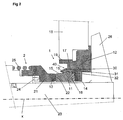
- Fig. 1 discloses a mechanical sealing device comprising a first part 1 and a second part 2.
- the mechanical sealing device is comprised in a pump.
- this pump application will be described, although it should be noted that the mechanical sealing device could be used also in other applications comprising a rotating shaft extending through a passage in a housing or the like, e.g. a mixer or an agitator.
- the first part 1 is substantially stationary, whereas the second part 2 is rotating around an axis x of rotation. It is to be noted, however, that the first part 1 could be rotating and the second part 2 could be stationary or substantially stationary. It is also possible to let both the first part 1 and the second part be rotating at different rotary speeds.
- the first part 1 comprises a first seal element 11 and a first holder element 12 for holding the first seal element 11.
- the first seal element 11 forms a first seal surface 13, an opposite backing surface 14 and an outer peripheral surface 15.
- the first seal surface 13 and the opposite backing surface 14 are parallel to each other and to a radial plane with respect to the axis x of rotation.
- the first holder element 12 has a support surface 16 and an inner surface 17.
- the outer peripheral surface 15 and the inner surface 17 are concentric with the axis x of rotation.
- the first part 1 also comprises, or is mounted in, a housing 18.
- the housing 18 is in the embodiments disclosed stationary, or substantially stationary.
- the first holder element 12 is connected to the housing 18 by means of a thread engagement, schematically indicated at 19.
- the first holder element 12 comprises an outer peripheral thread engaged by an inner thread of an opening through the housing 18.
- the second part 2 comprises a second seal element 21 forming a second seal surface 22.
- the second part 2 also comprises, or is mounted to, a rotary shaft 23.
- the second seal element 21 is axially displaceable along the axis x of rotation with respect to the rotary shaft 23, but is fixed to the rotary shaft 23 in a peripheral direction by means of any suitable coupling element 24.
- first part 1 with the first seal element 11 and the second part 2 with the second seal element 21 are rotary in relation to each other with respect to the axis x of rotation so that the first seal surface 13 abuts tightly and sealingly, during mutual rotation, the second seal surface 22 in a radial plane with respect to the axis x of rotation.
- the second seal element 21 is urged towards the first seal element 11 by means of a spring element 25.
- the shaft 23 carries, in the pump application disclosed, a schematically indicated impeller 26.
- the opposite backing surface 14 of the first seal element 11 abuts the support surface 16 of the first holder element 12.
- the surfaces 14 and 16 are planar or substantially planar, and configured in such that a tight abutment is achieved, i.e. the surfaces 14 and 16 abut each other tightly or sealingly. Thanks to the spring element 25, the opposite backing surface 14 and the support surface 16 will be urged to tight abutment against each other.
- the first part 1 also comprises an elastomer element 30 provided between the outer peripheral surface 15 of the first seal element 11 and the inner surface 17 of the first holder element 12.
- the first seal element 11 comprises a surrounding groove 31, which extends inwardly from the outer peripheral surface 15 and which, in the first embodiment, is disposed at a corner formed between the opposite backing surface 14 and the outer peripheral surface 15.
- the elastomer element 30 comprises an annular flange 32, which is complementary to the surrounding groove 31 and extends inwardly into the groove 31. In the first embodiment, the elastomer element 30 will thus abut the support surface 16 and the inner surface 17 of the first holder element 12. Thanks to the groove 31 and the annular flange 32, the elastomer element 30 will be secured in the surrounding annular space formed between the outer peripheral surface 15 of the first seal element 11 and the inner surface 17 of the first holder element 12.
- the first holder element 12 may comprise locking means 40 adapted to secure the elastomer element 30 between the outer peripheral surface 15 and the inner surface 17.
- the locking means 40 comprises a locking flange 41 projecting axially from the inner surface 17.
- the locking flange 41 is somewhat bent towards the outer peripheral surface 15 of the first seal element 11. This bending of the locking flange 41 further secures the elastomer element 30 in the annular space between the outer peripheral surface 15 and the inner surface 17.
- the outer peripheral surface 15 may have an inclined surface portion 15' tapering towards the first seal surface 13.
- the locking flange 41 is provided opposite and outside the inclined surface portion 15' in order to extend substantially in parallel with the inclined surface portion 15'.
- the elastomer element 30 may be manufactured in any suitable elastic polymer material, synthetic rubber or natural rubber.
- the first seal element 11 and the second seal element 21 are preferably manufactured in a material selected from the group comprising a metallic material, a ceramic material, a carbide material and a nitride material.
- the first holder element 12 is preferably manufactured in a rigid, non-elastic material, for instance a metallic material.
- Fig. 2 discloses a second embodiment, which differs from the first embodiment, merely in that the annular flange 32 of the elastomer element 30 extends from the outer peripheral surface 15 at a distance from the opposite backing surface 14.
- Fig. 3 discloses a third embodiment, which differs from the first embodiment in that the locking means 40, instead of the locking flange 41, comprises a locking ring 42 extending along a radial plane with respect to the axis x of rotation and attached to the first holder element 12 by means of any suitable attachment, for instance a number of screws 43. According to the third element, it can also be dispensed with the inclined surface portion 15' of the outer peripheral surface 15 of the first seal element 11.
- first seal element, first holder element and the elastomer element may be rotating and connected to the rotary shaft, whereas the second seal element is connected to the stationary housing.
Landscapes
- Engineering & Computer Science (AREA)
- General Engineering & Computer Science (AREA)
- Mechanical Engineering (AREA)
- Mechanical Sealing (AREA)
- Structures Of Non-Positive Displacement Pumps (AREA)
Claims (15)
- Mechanische Verschlussvorrichtung,
mit einem ersten Teil (1), das ein erstes Dichtungselement (11) und ein erstes Halteelement (12) zum Halten des ersten Dichtungselementes besitzt, wobei das erste Dichtungselement (11) eine erste Dichtungsoberfläche (13), eine gegenüberliegende Stützoberfläche (14) und eine äußere periphere Oberfläche (15) bildet, und wobei das erste Halteelement (12) eine Stützfläche (16) und eine innere Oberfläche (17) hat, und
einem zweiten Teil (2) mit einem zweiten Dichtungselement (21), das eine zweite Dichtungsoberfläche (22) bildet,
wobei der erste Teil (1) und der zweite Teil (2) relativ zueinander in Bezug auf eine Rotationsachse (x) drehbar sind, so dass die erste Dichtungsoberfläche (13) in einer radialen Ebene bezüglich der Rotationsachse (x) abdichtend an der zweiten Dichtungsoberfläche (22) anliegt, und
wobei ein elastomeres Element (30) zwischen der äußeren peripheren Oberfläche (15) und dem ersten Dichtungselement (11) und der inneren Oberfläche (17) des ersten Halteelementes (12) vorgesehen ist, und
wobei die gegenüberliegende Stützoberfläche (14) des ersten Dichtungselementes (11) fest an der Stützfläche (16) des ersten Halteelementes (12) anliegt,
das erste Dichtungselement (11) eine umlaufende Nut (31) besitzt, dadurch gekennzeichnet, dass
das elastomere Element (30) einen ringförmigen Flansch (32) aufweist, der sich einwärts in die Nut (31) erstreckt, und dass das erste Halteelement Verriegelungsmittel (40) enthält, die zur Sicherung des elastomeren Elementes (30) zwischen der äußeren peripheren Oberfläche (15) und der inneren Oberfläche (17) angepasst sind. - Mechanische Verschlussvorrichtung nach Anspruch 1, bei der die äußere periphere Oberfläche (15) und die innere Oberfläche (17) konzentrisch zur Rotationsachse (x) liegen.
- Mechanische Verschlussvorrichtung nach einem der Ansprüche 1 und 2, bei der die gegenüberliegende Stützfläche (14) und die Stützfläche (16) sich in radialer Ebene in Bezug auf die Rotationsachse (x) erstrecken.
- Mechanische Verschlussvorrichtung nach einem der vorhergehenden Ansprüche, bei der die umlaufende Nut (31) sich einwärts von der äußeren peripheren Oberfläche (15) erstreckt.
- Mechanische Verschlussvorrichtung nach Anspruch 4, bei der die umlaufende Nut (31) zwischen der gegenüberliegenden Stützfläche (14) und der äußeren peripheren Oberfläche (15) angeordnet ist.
- Mechanische Verschlussvorrichtung nach einem der vorhergehenden Ansprüche, bei der die Verriegelungsmittel (40) einen Verriegelungskragen (41) aufweisen, der axial aus der inneren Oberfläche (17) herausragt und in Richtung der äußeren Oberfläche (15) gekrümmt ist.
- Mechanische Verschlussvorrichtung nach einem der vorhergehenden Ansprüche, bei der die äußere periphere Oberfläche (15) einen geneigten Oberflächenteil (15') hat, der sich in Richtung der ersten Dichtungsoberfläche (13) verjüngt.
- Mechanische Verschlussvorrichtung nach einem der Ansprüche 6 und 7, bei der der Verriegelungskragen (41) gegenüberliegend und außerhalb des geneigten Oberflächenteils (15') vorgesehen ist.
- Mechanische Verschlussvorrichtung nach einem der vorhergehenden Ansprüche, bei der das erste und das zweite Dichtungselement (11, 21) aus einem Material gefertigt sind, das aus der Gruppe eines metallischen Materials, eines keramischen Materials, eines Hartmetall-Materials und eines Nitrid-Materials ausgewählt ist.
- Mechanische Verschlussvorrichtung nach einem der vorhergehenden Ansprüche, bei der das erste Halteelement (12) aus einem festen, nicht elastischen Material gefertigt ist.
- Mechanische Verschlussvorrichtung nach einem der vorhergehenden Ansprüche, bei der das erste Halteelement (12) mittels eines Gewindeeingriffs (19) in ein Gehäuse (18) eingreift.
- Pumpe mit einer mechanischen Verschlussvorrichtung nach Anspruch 1.
- Pumpe nach Anspruch 12, bei der der erste Teil ein Gehäuse (18) besitzt.
- Pumpe nach Anspruch 13, bei der das erste Halteelement (12) mittels eines Gewindeeingriffs (19) in das Gehäuse (18) eingreift.
- Pumpe nach einem der Ansprüche 12 bis 14, bei der der zweite Teil einen Schaft (23) besitzt.
Applications Claiming Priority (2)
| Application Number | Priority Date | Filing Date | Title |
|---|---|---|---|
| SE0701091A SE531210C2 (sv) | 2007-05-07 | 2007-05-07 | Mekanisk tätningsanordning samt pump |
| PCT/SE2008/050526 WO2008136757A1 (en) | 2007-05-07 | 2008-05-07 | A mechanical sealing device, and a pump |
Publications (3)
| Publication Number | Publication Date |
|---|---|
| EP2145123A1 EP2145123A1 (de) | 2010-01-20 |
| EP2145123A4 EP2145123A4 (de) | 2014-11-05 |
| EP2145123B1 true EP2145123B1 (de) | 2016-01-27 |
Family
ID=39943764
Family Applications (1)
| Application Number | Title | Priority Date | Filing Date |
|---|---|---|---|
| EP08767137.6A Active EP2145123B1 (de) | 2007-05-07 | 2008-05-07 | Mechanische verschlussvorrichtung und pumpe |
Country Status (5)
| Country | Link |
|---|---|
| US (1) | US8167315B2 (de) |
| EP (1) | EP2145123B1 (de) |
| CN (1) | CN101688612B (de) |
| SE (1) | SE531210C2 (de) |
| WO (1) | WO2008136757A1 (de) |
Families Citing this family (10)
| Publication number | Priority date | Publication date | Assignee | Title |
|---|---|---|---|---|
| WO2010098704A1 (en) * | 2009-02-26 | 2010-09-02 | Roplan International Ab | A mechanical sealing device |
| AU2010225452B2 (en) * | 2009-03-16 | 2016-06-09 | Vulco S.A. | Mechanical seal |
| DE102012108354B4 (de) * | 2012-09-07 | 2016-05-12 | Herborner Pumpenfabrik J. H. Hoffmann Gmbh & Co. Kg | Pumpe und Protektor für Pumpe |
| JP5922796B2 (ja) * | 2012-12-06 | 2016-05-24 | 三菱重工コンプレッサ株式会社 | シール装置、および、回転機械 |
| DE102013007163A1 (de) * | 2013-04-24 | 2014-11-13 | Eagleburgmann Germany Gmbh & Co. Kg | Gleitringdichtung mit positionsgenauer Bandage |
| SE537859C2 (sv) * | 2014-02-13 | 2015-11-03 | Scania Cv Ab | Plantätning |
| US9599229B2 (en) * | 2014-10-21 | 2017-03-21 | Gary K. Evans | Cartridge seal for a centrifugal pump |
| SE539433C2 (sv) | 2015-12-11 | 2017-09-19 | Roplan Holding Ab | Hållaranordning för att applicera ett tätningselement på en axel, tätningsanordning innefattande en sådan hållaranordning samt hydrodynamisk maskin innefattande sådan tätningsanordning |
| SE542626C2 (en) | 2018-04-11 | 2020-06-23 | Roplan Holding Ab | A pump housing device for a fluid pump, and a fluid pump |
| WO2023141263A1 (en) * | 2022-01-21 | 2023-07-27 | Raytheon Technologies Corporation | Carbon face seal |
Family Cites Families (29)
| Publication number | Priority date | Publication date | Assignee | Title |
|---|---|---|---|---|
| GB762950A (en) * | 1953-05-13 | 1956-12-05 | Beldam Asbestos Company Ltd | Improvements relating to liquid sealing devices for rotatable shafts |
| US2785913A (en) * | 1954-04-20 | 1957-03-19 | Crane Packing Co | Rotary mechanical seal with ceramic seat |
| US2888280A (en) * | 1954-06-30 | 1959-05-26 | Muskegon Piston Ring Co Inc | Seal |
| US3291493A (en) * | 1965-07-27 | 1966-12-13 | Chicago Rawhide Mfg Co | End face seal |
| US3441284A (en) * | 1966-06-17 | 1969-04-29 | Filton Ltd | Reversible mechanical seal |
| US3961799A (en) * | 1975-09-29 | 1976-06-08 | Sealol, Inc. | Conversion kit |
| GB2044862B (en) | 1979-03-16 | 1982-09-22 | Angus George Co Ltd | Mechanical seal for preventing fluid leakage |
| US4314704A (en) * | 1980-03-10 | 1982-02-09 | Crane Packing Limited | Rotary mechanical face seals |
| US4261581A (en) * | 1980-04-14 | 1981-04-14 | Durametallic Corporation | Mechanical seal with improved face ring mounting |
| US4327921A (en) * | 1980-12-08 | 1982-05-04 | Caterpillar Tractor Co. | Pressure balanced - constant engagement force seal |
| FR2610688B1 (fr) | 1987-02-10 | 1990-06-01 | Cyclam | Bague d'etancheite |
| US4779876A (en) * | 1987-05-11 | 1988-10-25 | John Crane-Houdaille. Inc. | Drive for banded washer type seal |
| US5071318A (en) * | 1990-01-22 | 1991-12-10 | Westinghouse Electric Corp. | Reactor coolant pump having improved dynamic secondary seal assembly |
| US5249812A (en) * | 1990-03-12 | 1993-10-05 | John Crane Inc. | Barrier seal systems |
| US5375852A (en) * | 1991-04-08 | 1994-12-27 | Chicago-Allis Manufacturing Corporation | Rotating seal body for face type seal |
| GB9121565D0 (en) * | 1991-10-10 | 1991-11-27 | Aes Eng Ltd | Mechanical seals |
| GB9121683D0 (en) * | 1991-10-12 | 1991-11-27 | Aes Eng Ltd | Spring retainer |
| US5370401A (en) * | 1992-06-30 | 1994-12-06 | Eg&G Sealol, Inc. | Antirotational and axial force component in a pusher seal assembly and tool for wear installation |
| US5375853B1 (en) * | 1992-09-18 | 1998-05-05 | Crane John Inc | Gas lubricated barrier seal |
| DE4436879B4 (de) * | 1994-03-19 | 2007-10-18 | Kaco Gmbh + Co | Dichtungseinheit |
| GB9606815D0 (en) | 1996-03-30 | 1996-06-05 | Crane John Uk Ltd | Mechanical face seals |
| DE19620950C2 (de) * | 1996-05-24 | 1999-08-26 | Freudenberg Carl Fa | Gleitringdichtung |
| US5758880A (en) * | 1996-08-28 | 1998-06-02 | Freudenberg-Nok General Partnership | Self piloting seal head assembly |
| DE19914930A1 (de) * | 1999-04-01 | 2000-10-19 | Freudenberg Carl Fa | Gleitringdichtung |
| CN1314978A (zh) * | 1999-04-23 | 2001-09-26 | 株式会社丰田自动织机制作所 | 压缩机的机械密封装置 |
| US6398223B1 (en) * | 2000-08-21 | 2002-06-04 | John Crane Inc. | Mechanical face seal |
| JP4180832B2 (ja) * | 2002-04-24 | 2008-11-12 | イーグル工業株式会社 | メカニカルシール装置 |
| KR101331248B1 (ko) * | 2005-07-22 | 2013-11-26 | 이글 고오교 가부시키가이샤 | 메카니컬 실링장치 |
| US7431304B2 (en) * | 2005-11-17 | 2008-10-07 | Freudenberg-Nok General Partnership | Face seal with constriction ring |
-
2007
- 2007-05-07 SE SE0701091A patent/SE531210C2/sv unknown
-
2008
- 2008-05-07 EP EP08767137.6A patent/EP2145123B1/de active Active
- 2008-05-07 US US12/599,237 patent/US8167315B2/en active Active
- 2008-05-07 CN CN2008800238277A patent/CN101688612B/zh active Active
- 2008-05-07 WO PCT/SE2008/050526 patent/WO2008136757A1/en not_active Ceased
Also Published As
| Publication number | Publication date |
|---|---|
| US8167315B2 (en) | 2012-05-01 |
| EP2145123A4 (de) | 2014-11-05 |
| EP2145123A1 (de) | 2010-01-20 |
| CN101688612B (zh) | 2012-10-10 |
| WO2008136757A1 (en) | 2008-11-13 |
| SE531210C2 (sv) | 2009-01-20 |
| US20100254840A1 (en) | 2010-10-07 |
| CN101688612A (zh) | 2010-03-31 |
| SE0701091L (sv) | 2008-11-08 |
Similar Documents
| Publication | Publication Date | Title |
|---|---|---|
| US8167315B2 (en) | Mechanical sealing device, and a pump | |
| EP3159583B1 (de) | Mechanische dichtung | |
| US8485530B2 (en) | Axial face seal assembly | |
| US8720955B2 (en) | Connecting device for connecting a flexible container to a flange or a connecting ring | |
| EP0050882A1 (de) | Selbstdämpfende Dichtungsanordnung mit Balgen | |
| JP4002751B2 (ja) | メカニカルシール装置 | |
| CN104612999A (zh) | 具有改进的密封组件的机械密封件 | |
| EP2889518B1 (de) | Dichtungsvorrichtung | |
| EP3070379B1 (de) | Mechanische dichtung | |
| CN108368886B (zh) | 用于将密封元件施用在轴上的保持装置 | |
| EP2401534B1 (de) | Vorrichtung mit einer mechanischen dichtung | |
| FI75918C (fi) | Glidringstaetning. | |
| US7311307B2 (en) | Seal seat assembly with specialized features | |
| JP2017096349A (ja) | 軸継手およびポンプ装置 | |
| US10816045B2 (en) | Clutch structure | |
| WO1986004655A1 (en) | Mechanical seal | |
| CN205446711U (zh) | 机械密封装置 | |
| JP6196727B2 (ja) | 簡易な構造のメカニカルシール | |
| GB2312255A (en) | Cartridge seal | |
| CN112752917A (zh) | 具有集成rfid传感器的机械密封件 | |
| JP5630498B2 (ja) | メカニカルシール装置 | |
| EP3561342B1 (de) | Mechanische abdichtungsvorrichtung | |
| JP4378085B2 (ja) | メカニカルシール装置 | |
| EP3837456B1 (de) | Absperrvorrichtung zur abdichtung einer welle einer rotationsmaschine sowie rotationsmaschine | |
| US20220275806A1 (en) | Seal arrangement for pump |
Legal Events
| Date | Code | Title | Description |
|---|---|---|---|
| PUAI | Public reference made under article 153(3) epc to a published international application that has entered the european phase |
Free format text: ORIGINAL CODE: 0009012 |
|
| 17P | Request for examination filed |
Effective date: 20091109 |
|
| AK | Designated contracting states |
Kind code of ref document: A1 Designated state(s): AT BE BG CH CY CZ DE DK EE ES FI FR GB GR HR HU IE IS IT LI LT LU LV MC MT NL NO PL PT RO SE SI SK TR |
|
| AX | Request for extension of the european patent |
Extension state: AL BA MK RS |
|
| DAX | Request for extension of the european patent (deleted) | ||
| A4 | Supplementary search report drawn up and despatched |
Effective date: 20141006 |
|
| RIC1 | Information provided on ipc code assigned before grant |
Ipc: F04D 29/12 20060101ALI20140929BHEP Ipc: F16J 15/34 20060101AFI20140929BHEP Ipc: F16J 15/38 20060101ALI20140929BHEP |
|
| GRAP | Despatch of communication of intention to grant a patent |
Free format text: ORIGINAL CODE: EPIDOSNIGR1 |
|
| INTG | Intention to grant announced |
Effective date: 20150925 |
|
| RIC1 | Information provided on ipc code assigned before grant |
Ipc: F16J 15/34 20060101AFI20150914BHEP Ipc: F16J 15/38 20060101ALI20150914BHEP Ipc: F04D 29/12 20060101ALI20150914BHEP |
|
| GRAS | Grant fee paid |
Free format text: ORIGINAL CODE: EPIDOSNIGR3 |
|
| RAP1 | Party data changed (applicant data changed or rights of an application transferred) |
Owner name: ROPLAN HOLDING AB |
|
| GRAA | (expected) grant |
Free format text: ORIGINAL CODE: 0009210 |
|
| AK | Designated contracting states |
Kind code of ref document: B1 Designated state(s): AT BE BG CH CY CZ DE DK EE ES FI FR GB GR HR HU IE IS IT LI LT LU LV MC MT NL NO PL PT RO SE SI SK TR |
|
| REG | Reference to a national code |
Ref country code: GB Ref legal event code: FG4D |
|
| REG | Reference to a national code |
Ref country code: CH Ref legal event code: NV Representative=s name: ING. MARCO ZARDI C/O M. ZARDI AND CO. S.A., CH Ref country code: CH Ref legal event code: EP |
|
| REG | Reference to a national code |
Ref country code: AT Ref legal event code: REF Ref document number: 772874 Country of ref document: AT Kind code of ref document: T Effective date: 20160215 |
|
| REG | Reference to a national code |
Ref country code: IE Ref legal event code: FG4D |
|
| REG | Reference to a national code |
Ref country code: DE Ref legal event code: R096 Ref document number: 602008042177 Country of ref document: DE |
|
| REG | Reference to a national code |
Ref country code: LT Ref legal event code: MG4D |
|
| REG | Reference to a national code |
Ref country code: NL Ref legal event code: MP Effective date: 20160127 |
|
| REG | Reference to a national code |
Ref country code: AT Ref legal event code: MK05 Ref document number: 772874 Country of ref document: AT Kind code of ref document: T Effective date: 20160127 |
|
| PG25 | Lapsed in a contracting state [announced via postgrant information from national office to epo] |
Ref country code: NL Free format text: LAPSE BECAUSE OF FAILURE TO SUBMIT A TRANSLATION OF THE DESCRIPTION OR TO PAY THE FEE WITHIN THE PRESCRIBED TIME-LIMIT Effective date: 20160127 |
|
| PG25 | Lapsed in a contracting state [announced via postgrant information from national office to epo] |
Ref country code: GR Free format text: LAPSE BECAUSE OF FAILURE TO SUBMIT A TRANSLATION OF THE DESCRIPTION OR TO PAY THE FEE WITHIN THE PRESCRIBED TIME-LIMIT Effective date: 20160428 Ref country code: NO Free format text: LAPSE BECAUSE OF FAILURE TO SUBMIT A TRANSLATION OF THE DESCRIPTION OR TO PAY THE FEE WITHIN THE PRESCRIBED TIME-LIMIT Effective date: 20160427 Ref country code: ES Free format text: LAPSE BECAUSE OF FAILURE TO SUBMIT A TRANSLATION OF THE DESCRIPTION OR TO PAY THE FEE WITHIN THE PRESCRIBED TIME-LIMIT Effective date: 20160127 Ref country code: HR Free format text: LAPSE BECAUSE OF FAILURE TO SUBMIT A TRANSLATION OF THE DESCRIPTION OR TO PAY THE FEE WITHIN THE PRESCRIBED TIME-LIMIT Effective date: 20160127 Ref country code: IT Free format text: LAPSE BECAUSE OF FAILURE TO SUBMIT A TRANSLATION OF THE DESCRIPTION OR TO PAY THE FEE WITHIN THE PRESCRIBED TIME-LIMIT Effective date: 20160127 Ref country code: FI Free format text: LAPSE BECAUSE OF FAILURE TO SUBMIT A TRANSLATION OF THE DESCRIPTION OR TO PAY THE FEE WITHIN THE PRESCRIBED TIME-LIMIT Effective date: 20160127 |
|
| PG25 | Lapsed in a contracting state [announced via postgrant information from national office to epo] |
Ref country code: AT Free format text: LAPSE BECAUSE OF FAILURE TO SUBMIT A TRANSLATION OF THE DESCRIPTION OR TO PAY THE FEE WITHIN THE PRESCRIBED TIME-LIMIT Effective date: 20160127 Ref country code: PT Free format text: LAPSE BECAUSE OF FAILURE TO SUBMIT A TRANSLATION OF THE DESCRIPTION OR TO PAY THE FEE WITHIN THE PRESCRIBED TIME-LIMIT Effective date: 20160527 Ref country code: LT Free format text: LAPSE BECAUSE OF FAILURE TO SUBMIT A TRANSLATION OF THE DESCRIPTION OR TO PAY THE FEE WITHIN THE PRESCRIBED TIME-LIMIT Effective date: 20160127 Ref country code: IS Free format text: LAPSE BECAUSE OF FAILURE TO SUBMIT A TRANSLATION OF THE DESCRIPTION OR TO PAY THE FEE WITHIN THE PRESCRIBED TIME-LIMIT Effective date: 20160527 Ref country code: SE Free format text: LAPSE BECAUSE OF FAILURE TO SUBMIT A TRANSLATION OF THE DESCRIPTION OR TO PAY THE FEE WITHIN THE PRESCRIBED TIME-LIMIT Effective date: 20160127 Ref country code: PL Free format text: LAPSE BECAUSE OF FAILURE TO SUBMIT A TRANSLATION OF THE DESCRIPTION OR TO PAY THE FEE WITHIN THE PRESCRIBED TIME-LIMIT Effective date: 20160127 Ref country code: BE Free format text: LAPSE BECAUSE OF NON-PAYMENT OF DUE FEES Effective date: 20160531 Ref country code: LV Free format text: LAPSE BECAUSE OF FAILURE TO SUBMIT A TRANSLATION OF THE DESCRIPTION OR TO PAY THE FEE WITHIN THE PRESCRIBED TIME-LIMIT Effective date: 20160127 |
|
| REG | Reference to a national code |
Ref country code: DE Ref legal event code: R097 Ref document number: 602008042177 Country of ref document: DE |
|
| PG25 | Lapsed in a contracting state [announced via postgrant information from national office to epo] |
Ref country code: EE Free format text: LAPSE BECAUSE OF FAILURE TO SUBMIT A TRANSLATION OF THE DESCRIPTION OR TO PAY THE FEE WITHIN THE PRESCRIBED TIME-LIMIT Effective date: 20160127 Ref country code: DK Free format text: LAPSE BECAUSE OF FAILURE TO SUBMIT A TRANSLATION OF THE DESCRIPTION OR TO PAY THE FEE WITHIN THE PRESCRIBED TIME-LIMIT Effective date: 20160127 |
|
| PG25 | Lapsed in a contracting state [announced via postgrant information from national office to epo] |
Ref country code: RO Free format text: LAPSE BECAUSE OF FAILURE TO SUBMIT A TRANSLATION OF THE DESCRIPTION OR TO PAY THE FEE WITHIN THE PRESCRIBED TIME-LIMIT Effective date: 20160127 Ref country code: CZ Free format text: LAPSE BECAUSE OF FAILURE TO SUBMIT A TRANSLATION OF THE DESCRIPTION OR TO PAY THE FEE WITHIN THE PRESCRIBED TIME-LIMIT Effective date: 20160127 Ref country code: SK Free format text: LAPSE BECAUSE OF FAILURE TO SUBMIT A TRANSLATION OF THE DESCRIPTION OR TO PAY THE FEE WITHIN THE PRESCRIBED TIME-LIMIT Effective date: 20160127 |
|
| PLBE | No opposition filed within time limit |
Free format text: ORIGINAL CODE: 0009261 |
|
| STAA | Information on the status of an ep patent application or granted ep patent |
Free format text: STATUS: NO OPPOSITION FILED WITHIN TIME LIMIT |
|
| PG25 | Lapsed in a contracting state [announced via postgrant information from national office to epo] |
Ref country code: BE Free format text: LAPSE BECAUSE OF FAILURE TO SUBMIT A TRANSLATION OF THE DESCRIPTION OR TO PAY THE FEE WITHIN THE PRESCRIBED TIME-LIMIT Effective date: 20160127 Ref country code: LU Free format text: LAPSE BECAUSE OF FAILURE TO SUBMIT A TRANSLATION OF THE DESCRIPTION OR TO PAY THE FEE WITHIN THE PRESCRIBED TIME-LIMIT Effective date: 20160507 |
|
| 26N | No opposition filed |
Effective date: 20161028 |
|
| REG | Reference to a national code |
Ref country code: IE Ref legal event code: MM4A |
|
| PG25 | Lapsed in a contracting state [announced via postgrant information from national office to epo] |
Ref country code: SI Free format text: LAPSE BECAUSE OF FAILURE TO SUBMIT A TRANSLATION OF THE DESCRIPTION OR TO PAY THE FEE WITHIN THE PRESCRIBED TIME-LIMIT Effective date: 20160127 Ref country code: BG Free format text: LAPSE BECAUSE OF FAILURE TO SUBMIT A TRANSLATION OF THE DESCRIPTION OR TO PAY THE FEE WITHIN THE PRESCRIBED TIME-LIMIT Effective date: 20160427 |
|
| REG | Reference to a national code |
Ref country code: FR Ref legal event code: ST Effective date: 20170131 |
|
| PG25 | Lapsed in a contracting state [announced via postgrant information from national office to epo] |
Ref country code: FR Free format text: LAPSE BECAUSE OF NON-PAYMENT OF DUE FEES Effective date: 20160531 |
|
| PG25 | Lapsed in a contracting state [announced via postgrant information from national office to epo] |
Ref country code: IE Free format text: LAPSE BECAUSE OF NON-PAYMENT OF DUE FEES Effective date: 20160507 |
|
| PG25 | Lapsed in a contracting state [announced via postgrant information from national office to epo] |
Ref country code: HU Free format text: LAPSE BECAUSE OF FAILURE TO SUBMIT A TRANSLATION OF THE DESCRIPTION OR TO PAY THE FEE WITHIN THE PRESCRIBED TIME-LIMIT; INVALID AB INITIO Effective date: 20080507 Ref country code: CY Free format text: LAPSE BECAUSE OF FAILURE TO SUBMIT A TRANSLATION OF THE DESCRIPTION OR TO PAY THE FEE WITHIN THE PRESCRIBED TIME-LIMIT Effective date: 20160127 |
|
| PG25 | Lapsed in a contracting state [announced via postgrant information from national office to epo] |
Ref country code: TR Free format text: LAPSE BECAUSE OF FAILURE TO SUBMIT A TRANSLATION OF THE DESCRIPTION OR TO PAY THE FEE WITHIN THE PRESCRIBED TIME-LIMIT Effective date: 20160127 Ref country code: MT Free format text: LAPSE BECAUSE OF NON-PAYMENT OF DUE FEES Effective date: 20160531 Ref country code: MC Free format text: LAPSE BECAUSE OF FAILURE TO SUBMIT A TRANSLATION OF THE DESCRIPTION OR TO PAY THE FEE WITHIN THE PRESCRIBED TIME-LIMIT Effective date: 20160127 |
|
| REG | Reference to a national code |
Ref country code: DE Ref legal event code: R082 Ref document number: 602008042177 Country of ref document: DE Representative=s name: PATENTANWAELTE VOMBERG & SCHART, DE Ref country code: DE Ref legal event code: R081 Ref document number: 602008042177 Country of ref document: DE Owner name: VELCORA HOLDING AB, SE Free format text: FORMER OWNER: ROPLAN HOLDING AB, TUMBA, SE |
|
| REG | Reference to a national code |
Ref country code: GB Ref legal event code: 732E Free format text: REGISTERED BETWEEN 20210422 AND 20210428 |
|
| REG | Reference to a national code |
Ref country code: DE Ref legal event code: R082 Ref document number: 602008042177 Country of ref document: DE Representative=s name: RGTH PATENTANWAELTE PARTGMBB, DE Ref country code: DE Ref legal event code: R082 Ref document number: 602008042177 Country of ref document: DE Representative=s name: RGTH RICHTER GERBAULET THIELEMANN HOFMANN PATE, DE |
|
| PGFP | Annual fee paid to national office [announced via postgrant information from national office to epo] |
Ref country code: DE Payment date: 20250521 Year of fee payment: 18 |
|
| PGFP | Annual fee paid to national office [announced via postgrant information from national office to epo] |
Ref country code: GB Payment date: 20250521 Year of fee payment: 18 |
|
| PGFP | Annual fee paid to national office [announced via postgrant information from national office to epo] |
Ref country code: CH Payment date: 20250601 Year of fee payment: 18 |