EP2145166B1 - Thermomètre à résistance - Google Patents
Thermomètre à résistance Download PDFInfo
- Publication number
- EP2145166B1 EP2145166B1 EP08750232.4A EP08750232A EP2145166B1 EP 2145166 B1 EP2145166 B1 EP 2145166B1 EP 08750232 A EP08750232 A EP 08750232A EP 2145166 B1 EP2145166 B1 EP 2145166B1
- Authority
- EP
- European Patent Office
- Prior art keywords
- substrate
- resistance thermometer
- thermal expansion
- expansion coefficient
- resistance
- Prior art date
- Legal status (The legal status is an assumption and is not a legal conclusion. Google has not performed a legal analysis and makes no representation as to the accuracy of the status listed.)
- Active
Links
Images
Classifications
-
- G—PHYSICS
- G01—MEASURING; TESTING
- G01K—MEASURING TEMPERATURE; MEASURING QUANTITY OF HEAT; THERMALLY-SENSITIVE ELEMENTS NOT OTHERWISE PROVIDED FOR
- G01K7/00—Measuring temperature based on the use of electric or magnetic elements directly sensitive to heat ; Power supply therefor, e.g. using thermoelectric elements
- G01K7/16—Measuring temperature based on the use of electric or magnetic elements directly sensitive to heat ; Power supply therefor, e.g. using thermoelectric elements using resistive elements
- G01K7/18—Measuring temperature based on the use of electric or magnetic elements directly sensitive to heat ; Power supply therefor, e.g. using thermoelectric elements using resistive elements the element being a linear resistance, e.g. platinum resistance thermometer
Definitions
- the invention relates to a resistance thermometer consisting of several components, comprising at least one substrate, which consists essentially of a material whose coefficient of thermal expansion is substantially greater than 10.5 ppm / K, at least one resistance element, which is arranged on the substrate is and at least one electrically insulating separation layer, which is arranged substantially between the resistance element and the substrate.
- resistive elements are known which are applied by thin-film techniques to an electrically insulating substrate.
- the thin film is usually made of platinum or nickel with or without doping and the substrate is usually made of Al 2 O 3 .
- the characteristic of the resistance thermometer has the desired characteristics when the coefficient of thermal expansion (TCE) of the magnesium titanate substrate is in the range between 8.5 and 10.5 ppm / K.
- TCE coefficient of thermal expansion
- Another resistance thermometer is in the document EP 0 471 138 A2 described.
- the substrate still has a very large influence on the characteristic curve or on the TCR value, ie the temperature coefficient of the resistance thermometer.
- the TCR value of the resistance thermometer in the vicinity of the material of the resistive element as a bulk material.
- Bulk material refers to a state of a material as opposed to thin film or powder, and means that the material is in a form so that it can be viewed as an infinite amount in all three dimensions from an atomic viewpoint.
- platinum measuring resistors with a TCR value in the range above 3900 ppm / K, which values are typical for wound measuring resistors made of pure platinum.
- the shape of the characteristic also deviates from the prescribed according to DIN IEC 751 in resistance thermometers with lower TCR values (typically at 3850 ppm / K). This has the consequence that the prescribed tolerance band is left, especially with wider temperature ranges or with high accuracy requirements.
- Other negative effects of poor material adaptation are the hysteresis (memory effect) and a lack of long-term stability of the measured values.
- the invention has for its object to provide a resistance thermometer whose temperature coefficient (TCR) is above 3900 ppm / K.
- N is the number of components of the resistance thermometer, wherein the running number i denotes the individual components, where TCE i denotes the coefficient of thermal expansion, d i the thickness and E i the elasticity of the individual components, and wherein F i takes into account a geometric factor and that effective thermal expansion coefficient TCE eff is greater than or equal to the thermal expansion coefficient of the bulk metal of the resistive element.
- the construction of the resistance thermometer thus consists at least of a substrate-separating-layer resistance element. Above all, the separating layer is necessary for preventing electrical contact between the substrate and the resistance element.
- the geometric factor F i of the individual components lies between 0 and 1 and takes into account inter alia the spatial arrangement of the individual components or of the individual layers. The formula returns a weighted interpolation via the resistance thermometer.
- An embodiment of the invention provides that the substrate consists essentially of a material whose thermal expansion coefficient is substantially greater than 11 ppm / K.
- An embodiment of the invention includes that the substrate consists essentially of a material whose thermal expansion coefficient is substantially between 10.5 and 13.5 ppm / K.
- An embodiment of the invention provides that the resistance element is applied with a thin-film technique on the substrate.
- thin film techniques are sputtering or vapor deposition.
- An embodiment of the invention includes that the resistance element consists essentially of platinum and / or nickel.
- An embodiment of the invention provides that the resistance element is provided free of a foreign alloy or with a foreign alloy.
- An embodiment of the invention includes that the resistance element has a layer thickness between 0.1 .mu.m and 5 .mu.m.
- a further embodiment of the invention provides that the resistance element has a layer thickness between 0.1 .mu.m and 2 .mu.m.
- An embodiment of the invention provides that the electrically insulating separating layer consists of glass, ceramic or glass ceramic.
- An embodiment of the invention includes that the electrically insulating separating layer has a thickness between 0.5 .mu.m and 100 .mu.m.
- An embodiment of the invention provides that the electrically insulating separating layer has a thickness between 0.5 ⁇ m and 50 ⁇ m.
- An embodiment of the invention provides that the electrically insulating separating layer has a thermal expansion coefficient between 0.4 and 8 ppm / K.
- An embodiment of the invention includes that at least one electrically insulating cover is provided, which is arranged substantially on the side facing away from the substrate side of the resistance element.
- an embodiment of the invention provides that the electrically insulating cover consists essentially of a glass, ceramic, glass ceramic or a polymer layer.
- An embodiment of the invention includes that the electrically insulating cover has a thickness between 0.5 .mu.m and 100 .mu.m.
- an embodiment of the invention provides that the substrate consists essentially of zirconium oxide.
- Zirconium oxide (ZrO 2 ) becomes electrically conductive from a temperature above 200 ° C, so that the above-mentioned separation layer between the substrate and the resistive element is advantageous.
- An embodiment of the invention includes that the thickness of the substrate is between 0.15 and 1.0 mm.
- An embodiment of the invention includes that the thickness of the substrate is between 0.15 and 0.5 mm.
- An embodiment of the invention includes that the thickness of the substrate is between 0.2 and 1.0 mm.
- Such thin substrates in particular of zirconium oxide, for example, have the advantages that they bring a low hysteresis of the resistance thermometer with it and also lead to an improved characteristic.
- a substrate of zirconia having a thickness of 0.38 mm results in a TCR of approximately 3913 ppm / K.
- an embodiment of the invention provides that the substrate consists essentially of zirconium oxide, that the thickness of the substrate is between 0.2 and 1.0 mm, and that the electrically insulating separating layer is arranged substantially between the resistance element and the substrate.
- the separating layer prevents electrical contact is because zirconium is electrically conductive above a temperature above about 200 ° C.
- the embodiment is advantageous in that the substrate consists essentially of a material whose thermal expansion coefficient is substantially between 10.5 and 13.5 ppm / K.
- the embodiment mentioned here entails that the resistance thermometer has a temperature coefficient above 3900 ppm / K.
- An embodiment of the invention provides that at least one inner compensation layer is provided on the side of the substrate facing away from the resistance element.
- the inner compensation layer serves to compensate for thermal expansion effects of the separation layer.
- An embodiment of the invention includes that the inner compensating layer is substantially the same as the separating layer with respect to a change in expansion caused by the temperature.
- An embodiment of the invention provides that the inner compensation layer consists essentially of the same material as the separation layer.
- An embodiment of the invention provides that at least one outer compensation layer is provided on the side of the substrate facing away from the resistance element.
- the outer compensating layer serves to compensate for thermal expansion effects of the cover.
- An embodiment of the invention includes that the outer compensation layer is arranged on the side facing away from the substrate side of the inner compensation unit.
- An embodiment of the invention provides that the outer compensation layer with respect to a caused by the temperature Change in extent essentially the same as the cover.
- An embodiment of the invention includes that the outer compensation layer consists essentially of the same material as the cover.
- An embodiment of the invention includes that the cover consists essentially of the same material as the separating layer.
- an embodiment of the invention provides that the substrate consists essentially of zirconium oxide, that the substrate has a thickness between 0.3 and 0.5 mm, that the resistance element consists essentially of platinum, that the resistance element has a thickness between 0.45 and 2 .mu.m, that the separating layer has a thickness between 0.5 and 40 microns and consists essentially of a glass-ceramic having a thermal expansion coefficient between 6 and 7.5 ppm / K, and that the cover has a thickness between 0.5 and 40 ⁇ m and consists essentially of a glass ceramic with a thermal expansion coefficient between 6 and 7.5 ppm / K.
- the temperature coefficient of the resistance thermometer being between 3910 and 3925 ppm / K.
- an embodiment of the invention provides that the substrate consists essentially of zirconium oxide, that the substrate has a thickness between 0.3 and 0.7 mm, that the resistance element consists essentially of platinum, that the resistance element has a thickness between 0.45 and 2 microns, that the separating layer has a thickness between 5 and 40 microns and consists essentially of a glass ceramic having a thermal expansion coefficient between 6 and 7.5 ppm / K, and the cover has a thickness between 5 and 40 ⁇ m and essentially consists of a glass ceramic with a thermal expansion coefficient between 6 and 7.5 ppm / K.
- the temperature coefficient of the resistance thermometer being between 3910 and 3925 ppm / K.
- the substrate consists essentially of zirconia, that the substrate has a thickness between 0.3 and 0.5 mm, that the resistance element consists essentially of platinum with at least one foreign alloy, that the Resistance element has a thickness between 0.45 and 2 microns that the separation layer has a thickness between 0.5 and 40 microns and consists essentially of a glass ceramic having a thermal expansion coefficient between 6 and 7.5 ppm / K, and that the cover a Thickness between 5 and 40 microns and consists essentially of a glass-ceramic with a thermal expansion coefficient between 6 and 7.5 ppm / K.
- Such an arrangement produces a temperature coefficient of the resistance thermometer of 3850 ppm / K with a characteristic according to DIN IEC 751.
- the substrate consists essentially of zirconium oxide, that the substrate has a thickness between 0.3 and 0.7 mm in that the resistance element consists essentially of platinum with at least one foreign alloy, that the resistance element has a thickness of between 0.45 and 2 ⁇ m, that the separation layer has a thickness of between 5 and 40 ⁇ m and essentially consists of a glass ceramic with a thermal expansion coefficient between 6 and 7.5 ppm / K, and that the cover has a thickness between 5 and 40 microns and in the Essentially consists of a glass ceramic with a thermal expansion coefficient between 6 and 7.5 ppm / K.
- Such an arrangement produces a temperature coefficient of the resistance thermometer of 3850 ppm / K with a characteristic according to DIN IEC 751.
- an embodiment of the invention provides that the substrate consists essentially of zirconium oxide, that the substrate has a thickness between 0.3 and 0.5 mm, that the resistance element consists essentially of nickel, that the resistance element has a thickness between 0.1 and 2 .mu.m, that the separating layer has a thickness between 0.5 and 40 microns, that the separating layer consists essentially of a glass ceramic, that the separating layer has a coefficient of thermal expansion between 6 and 7.5 ppm / K, and that the cover in Essentially consists of a polymer or glass.
- Such an arrangement effects a temperature coefficient of the resistance thermometer between 6700 and 6740 ppm / K.
- an embodiment of the invention provides that the substrate consists essentially of zirconium oxide, that the substrate has a thickness between 0.3 and 0.7 mm, that the resistance element consists essentially of nickel, that the resistance element has a thickness between 0.3 and 2 ⁇ m, that the separating layer has a thickness of between 5 and 40 ⁇ m, that the separating layer essentially consists of a glass ceramic, that the separating layer has a thermal expansion coefficient of between 6 and 7.5 ppm / K, and that the covering essentially consists of a polymer or glass.
- Such an arrangement effects a temperature coefficient of the resistance thermometer between 6700 and 6740 ppm / K.
- An embodiment of the invention includes that the substrate consists essentially of zirconia, which is stabilized between 3 mol% and 8 mol% with yttrium.
- An embodiment of the invention provides that the substrate consists essentially of zirconium oxide, which is stabilized between 3 mol% and 11 mol% with scandium.
- An embodiment of the invention includes that the substrate consists essentially of zirconia, which is stabilized between 0.5 mol% and 4 mol% with magnesium.
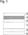
- a section through a schematic resistance thermometer is shown. Electrical contacts, housing, etc. are thus not shown. The temperature is determined by evaluating the electrical resistance. This requires knowledge of the characteristic of the resistance thermometer.
- the resistance thermometer or generally the temperature sensor consists here of a substrate 1, on which an electrically insulating separating layer 2 is applied.
- the resistance element 4 which serves for the actual measurement. It is a metal layer which has a suitable structure, eg a meander pattern, and is applied by thin film or thick film techniques.
- the separating layer 2 is particularly advantageous for the case that the substrate consists of zirconium oxide (ZrO 2 ), which in a Temperature above 200 ° C becomes electrically conductive. That is, the separating layer 2 prevents the direct electrical contact between the optionally conductive substrate 1 and the resistance element 4, which is designed and understood here in particular as a layer.
- a cover 5 is provided which serves inter alia the passivation and generally the protection of the metal layer of the resistive element 4.
- an inner 3 and an outer compensating layer 6 are furthermore provided, which in each case compensate for the changes in the expansion of the separating layer 2 or the cover 5 caused by the temperature.
- the compensation layers 3, 6 have substantially the same properties as the separation layer 2 or the cover 5 with respect to the thermal expansion properties.
- the inner compensation layer preferably consists of the same material as the separation layer 2 and both layers 2, 5 have the same dimensioning. The same applies to the outer leveling layer 6 and the cover. 5
- the resistance thermometer shown here thus consists of a total of 6 layers. For further understanding, these are numbered as follows: 1: substrate; 2: separating layer; 3: inner leveling layer; 4: resistance element; 5: cover and 6: outer leveling layer.
- Each of these layers has a thickness d i , a modulus of elasticity E i and a thermal expansion coefficient TCE i .
- each layer is characterized by a geometric shape factor F i between 0 and 1, which takes into account the spatial arrangement of the individual layers.
- TCE eff > TCE Bun metal of the material of the resistive element 4 as a bulk metal
- TCE eff of the resistance thermometer should be greater than or equal to the thermal expansion coefficient TCE bulk metal of the material of the resistive element 4 as a bulk metal be.
- the running number i refers to the individual layers.
- N is equal to 6 in the case shown.
- thermometer can then be dimensioned to suit the required temperature coefficient of the resistance thermometer.
- thermometer increases with the layer thickness of the substrate 1, wherein increasing the thickness of the separating layer 2 in turn reduces the temperature coefficient.
Landscapes
- Physics & Mathematics (AREA)
- General Physics & Mathematics (AREA)
- Thermistors And Varistors (AREA)
- Measuring Temperature Or Quantity Of Heat (AREA)
- Non-Adjustable Resistors (AREA)
Claims (15)
- Thermomètre à résistance électrique, constitué de plusieurs composants, comprenant au moins un substrat (1), qui est pour l'essentiel constitué d'un matériau dont le coefficient de dilatation thermique est pour l'essentiel supérieur à 10,5 ppp/K, au moins un élément résistif (4), qui est disposé sur le substrat (1), et au moins une couche de séparation électriquement isolante (2), qui est pour l'essentiel disposée entre l'élément résistif (4) et le substrat (1),
les composants (1, 2, 3, 4, 5, 6) du thermomètre à résistance électrique étant conçus et assortis les uns aux autres de telle sorte qu'un coefficient de dilatation thermique effectif TECeff résultant du thermomètre à résistance électrique correspond à une valeur prédéfinissable, le coefficient de dilatation thermique effectif TECeff du thermomètre à résistance électrique étant défini approximativement et pour l'essentiel par la formule suivante :
en ce que le coefficient de dilatation thermique effectif TECeff est supérieur ou égal au coefficient de dilatation thermique du métal en vrac de l'élément résistif (4),
caractérisé
en ce que, sur la base de la formule pour TCEeff, le thermomètre à résistance électrique est dimensionné de façon adaptée à un coefficient de température TCR nécessaire, supérieur à 3 900 ppm/K. - Thermomètre à résistance électrique selon la revendication 1,
caractérisé
en ce que le substrat (1) est constitué pour l'essentiel d'un matériau, dont le coefficient de dilatation thermique se situe pour l'essentiel entre 10,5 et 13,5 ppm/K. - Thermomètre à résistance électrique selon au moins l'une des revendications précédentes,
caractérisé
en ce que l'élément résistif (4) présente une épaisseur de couche comprise entre 0,1 µm et 2 µm. - Thermomètre à résistance électrique selon la revendication 1,
caractérisé
en ce que la couche de séparation électriquement isolante (2) présente une épaisseur comprise entre 0,5 µm et 50 µm. - Thermomètre à résistance électrique selon la revendication 1 ou 4, caractérisé
en ce que la couche de séparation électriquement isolante (2) présente un coefficient de dilatation thermique compris entre 0,4 et 8 ppm/K. - Thermomètre à résistance électrique selon au moins l'une des revendications précédentes,
caractérisé
en ce qu'est prévue au moins une protection électriquement isolante (5), laquelle est disposée pour l'essentiel sur le côté opposé au substrat (1) de l'élément résistif (4). - Thermomètre à résistance électrique selon la revendication 6,
caractérisé
en ce que la protection électriquement isolante (5) présente une épaisseur comprise entre 0,5 µm et 100 µm. - Thermomètre à résistance électrique selon au moins l'une des revendications précédentes,
caractérisé
en ce que le substrat (1) est constitué pour l'essentiel d'oxyde de zirconium. - Thermomètre à résistance électrique selon au moins l'une des revendications précédentes,
caractérisé
en ce que l'épaisseur du substrat (1) est comprise entre 0,15 et 0,5 mm. - Thermomètre à résistance électrique selon au moins l'une des revendications précédentes,
caractérisé
en ce que sur le côté opposé à l'élément résistif (4) du substrat (1) est prévue au moins une couche de compensation intérieure (3) et en ce que la couche de compensation intérieure (3) est constituée pour l'essentiel de façon identique à la couche de séparation (2) en ce qui concerne le changement de dilatation occasionné par la température. - Thermomètre à résistance électrique selon au moins l'une des revendications précédentes,
caractérisé
en ce que sur le côté opposé à l'élément résistif (4) du substrat (1) est prévue au moins une couche de compensation extérieure (3) et en ce que la couche de compensation extérieure (3) est constituée pour l'essentiel de façon identique à la protection (5) en ce qui concerne le changement de dilatation occasionné par la température. - Thermomètre à résistance électrique selon au moins l'une des revendications précédentes,
caractérisé
en ce que le substrat (1) est constitué pour l'essentiel d'oxyde de zirconium,
en ce que le substrat (1) présente une épaisseur comprise entre 0,3 et 0,5 mm, en ce que l'élément résistif (4) est constitué pour l'essentiel de platine,
en ce que l'élément résistif (4) présente une épaisseur comprise entre 0,45 et 2 µm,
en ce que la couche de séparation (2) présente une épaisseur comprise entre 0,5 et 40 µm et est constituée pour l'essentiel d'une vitrocéramique avec un coefficient de dilatation thermique compris entre 6 et 7,5 ppm/K, et
en ce que la protection (5) présente une épaisseur comprise entre 5 et 40 µm et est pour l'essentiel constituée d'une vitrocéramique avec un coefficient de dilatation thermique compris entre 6 et 7,5 ppm/K. - Thermomètre à résistance électrique selon au moins l'une des revendications 1 à 11,
caractérisé
en ce que le substrat (1) est constitué pour l'essentiel d'oxyde de zirconium,
en ce que le substrat (1) présente une épaisseur comprise entre 0,3 et 0,5 mm, en ce que l'élément résistif (4) est constitué pour l'essentiel de nickel,
en ce que l'élément résistif (4) présente une épaisseur comprise entre 0,1 et 2 µm,
en ce que la couche de séparation (2) présente une épaisseur comprise entre 0,5 et 40 µm,
en ce que la couche de séparation (2) est constituée pour l'essentiel d'une vitrocéramique,
en ce que la couche de séparation (2) présente un coefficient de dilatation thermique compris entre 6 et 7,5 ppm/K,
et
en ce que la protection (5) est pour l'essentiel constituée d'un polymère ou de verre. - Thermomètre à résistance électrique selon au moins l'une des revendications précédentes,
caractérisé
en ce que le substrat (1) est pour l'essentiel constitué d'oxyde de zirconium, lequel est stabilisé entre 3 moles pour cent et 11 moles pour cent avec du scandium ou entre 0,5 mole pour cent et 4 moles pour cent avec du magnésium. - Procédé destiné à la fabrication d'un thermomètre à résistance électrique, le thermomètre à résistance électrique étant constitué de plusieurs composants, comprenant au moins un substrat (1), qui est pour l'essentiel constitué d'un matériau dont le coefficient de dilatation thermique est pour l'essentiel supérieur à 10,5 ppp/K, au moins un élément résistif (4), qui est disposé sur le substrat (1), et au moins une couche de séparation électriquement isolante (2), qui est pour l'essentiel disposée entre l'élément résistif (4) et le substrat (1),
les composants (1, 2, 3, 4, 5, 6) du thermomètre à résistance électrique étant conçus et assortis les uns aux autres de telle sorte qu'un coefficient de dilatation thermique effectif TECeff résultant du thermomètre à résistance électrique correspond à une valeur prédéfinissable, le coefficient de dilatation thermique effectif TECeff du thermomètre à résistance électrique étant défini approximativement et pour l'essentiel par la formule suivante :
en ce que le coefficient de dilatation thermique effectif TECeff est supérieur ou égal au coefficient de dilatation thermique du métal en vrac de l'élément résistif (4),
caractérisé
en ce que, sur la base de la formule pour TCEeff, le thermomètre à résistance électrique est dimensionné de façon adaptée à un coefficient de température TCR nécessaire.
Priority Applications (1)
| Application Number | Priority Date | Filing Date | Title |
|---|---|---|---|
| EP17167473.2A EP3327415B1 (fr) | 2007-05-16 | 2008-05-09 | Thermomètre à résistance |
Applications Claiming Priority (2)
| Application Number | Priority Date | Filing Date | Title |
|---|---|---|---|
| DE102007023434.3A DE102007023434B4 (de) | 2007-05-16 | 2007-05-16 | Widerstandsthermometer |
| PCT/EP2008/055748 WO2008138887A1 (fr) | 2007-05-16 | 2008-05-09 | Thermomètre à résistance |
Related Child Applications (2)
| Application Number | Title | Priority Date | Filing Date |
|---|---|---|---|
| EP17167473.2A Division EP3327415B1 (fr) | 2007-05-16 | 2008-05-09 | Thermomètre à résistance |
| EP17167473.2A Division-Into EP3327415B1 (fr) | 2007-05-16 | 2008-05-09 | Thermomètre à résistance |
Publications (3)
| Publication Number | Publication Date |
|---|---|
| EP2145166A1 EP2145166A1 (fr) | 2010-01-20 |
| EP2145166B1 true EP2145166B1 (fr) | 2017-07-05 |
| EP2145166B8 EP2145166B8 (fr) | 2017-08-23 |
Family
ID=39739589
Family Applications (2)
| Application Number | Title | Priority Date | Filing Date |
|---|---|---|---|
| EP17167473.2A Active EP3327415B1 (fr) | 2007-05-16 | 2008-05-09 | Thermomètre à résistance |
| EP08750232.4A Active EP2145166B8 (fr) | 2007-05-16 | 2008-05-09 | Thermomètre à résistance |
Family Applications Before (1)
| Application Number | Title | Priority Date | Filing Date |
|---|---|---|---|
| EP17167473.2A Active EP3327415B1 (fr) | 2007-05-16 | 2008-05-09 | Thermomètre à résistance |
Country Status (5)
| Country | Link |
|---|---|
| US (1) | US8106740B2 (fr) |
| EP (2) | EP3327415B1 (fr) |
| DE (1) | DE102007023434B4 (fr) |
| RU (1) | RU2426975C1 (fr) |
| WO (1) | WO2008138887A1 (fr) |
Families Citing this family (10)
| Publication number | Priority date | Publication date | Assignee | Title |
|---|---|---|---|---|
| DE102009007940B4 (de) * | 2009-02-06 | 2010-11-18 | Heraeus Sensor Technology Gmbh | Nichtleitfähiges Zirkonoxid |
| DE102012110210B4 (de) * | 2012-10-25 | 2017-06-01 | Heraeus Sensor Technology Gmbh | Hochtemperaturchip mit hoher Stabilität |
| JP6404726B2 (ja) * | 2014-03-07 | 2018-10-17 | 日本特殊陶業株式会社 | 感温素子及び温度センサ |
| DE102014104219B4 (de) | 2014-03-26 | 2019-09-12 | Heraeus Nexensos Gmbh | Keramikträger sowie Sensorelement, Heizelement und Sensormodul jeweils mit einem Keramikträger und Verfahren zur Herstellung eines Keramikträgers |
| DE102015223951B4 (de) * | 2015-12-01 | 2022-12-01 | TE Connectivity Sensors Germany GmbH | Substrat für eine Sensoranordnung für ein Widerstandsthermometer, Sensoranordnung und Widerstandsthermometer |
| DE102015223950A1 (de) * | 2015-12-01 | 2017-06-01 | TE Connectivity Sensors Germany GmbH | Substrat für eine Sensoranordnung für ein Widerstandsthermometer, Sensoranordnung, Widerstandsthermometer und Verfahren zur Herstellung eines solchen Substrats |
| DE102016106675B3 (de) | 2016-04-12 | 2017-08-24 | Innovative Sensor Technology Ist Ag | Dünnschichtsensorelement für ein Widerstandsthermometer |
| DE102018110889A1 (de) * | 2017-05-16 | 2018-11-22 | Koa Corporation | Temperatursensor-Element |
| CN109446712B (zh) * | 2018-11-12 | 2020-09-11 | 广东电网有限责任公司 | 温度计算方法及装置 |
| DE102021116345A1 (de) | 2021-06-24 | 2022-12-29 | Schott Ag | Einheit für Hochtemperaturanwendungen |
Family Cites Families (21)
| Publication number | Priority date | Publication date | Assignee | Title |
|---|---|---|---|---|
| US3866158A (en) * | 1972-08-18 | 1975-02-11 | Degussa | Resistance thermometer |
| DE2507731C3 (de) * | 1975-02-22 | 1978-09-07 | Deutsche Gold- Und Silber-Scheideanstalt Vormals Roessler, 6000 Frankfurt | Meßwiderstand für Widerstandsthermometer und Verfahren zu seiner Herstellung |
| US4722609A (en) * | 1985-05-28 | 1988-02-02 | The United States Of America As Represented By The Secretary Of The Navy | High frequency response multilayer heat flux gauge configuration |
| US4803457A (en) * | 1987-02-27 | 1989-02-07 | Chapel Jr Roy W | Compound resistor and manufacturing method therefore |
| JPH0258304A (ja) | 1988-08-24 | 1990-02-27 | Matsushita Electric Ind Co Ltd | 薄膜白金温度センサ |
| DE4020383C2 (de) * | 1990-06-27 | 1999-04-01 | Bosch Gmbh Robert | Verfahren zum Schutz von Katalysatoren für die Abgasreinigung sowie Wärmetönungssensor zur Durchführung des Verfahrens |
| DE4026061C1 (fr) * | 1990-08-17 | 1992-02-13 | Heraeus Sensor Gmbh, 6450 Hanau, De | |
| JPH04265828A (ja) * | 1991-02-20 | 1992-09-22 | Murata Mfg Co Ltd | 白金温度センサ |
| DE4300084C2 (de) | 1993-01-06 | 1995-07-27 | Heraeus Sensor Gmbh | Widerstandsthermometer mit einem Meßwiderstand |
| EP0651236A1 (fr) * | 1993-10-27 | 1995-05-03 | GITEM Technical and Production Complex of SEPO JSCo | Thermomètre de surface à résistance à couche mince |
| DE19540194C1 (de) * | 1995-10-30 | 1997-02-20 | Heraeus Sensor Gmbh | Widerstandsthermometer aus einem Metall der Platingruppe |
| US5896081A (en) * | 1997-06-10 | 1999-04-20 | Cyntec Company | Resistance temperature detector (RTD) formed with a surface-mount-device (SMD) structure |
| DE19757258C2 (de) * | 1997-12-23 | 2001-02-08 | Heraeus Electro Nite Int | Sensor mit temperaturabhängigem Meßwiderstand und dessen Verwendung zur Temperaturmessung |
| US6004471A (en) * | 1998-02-05 | 1999-12-21 | Opto Tech Corporation | Structure of the sensing element of a platinum resistance thermometer and method for manufacturing the same |
| EP0973020B1 (fr) * | 1998-07-16 | 2009-06-03 | EPIQ Sensor-Nite N.V. | Capteur de température électrique comprenant une multi-couche |
| DE19848524C1 (de) * | 1998-10-21 | 1999-12-16 | Dresden Ev Inst Festkoerper | Verfahren zur Herstellung hochintegrationsfähiger Platin-Dünnschichtwiderstände |
| DE19934109C1 (de) * | 1999-07-21 | 2001-04-05 | Bosch Gmbh Robert | Temperaturfühler und Verfahren zu seiner Herstellung |
| DE10065723A1 (de) * | 2000-12-29 | 2002-07-04 | Bosch Gmbh Robert | Anordnung zur Temperaturmessung und -regelung |
| DE10208533B4 (de) * | 2002-02-27 | 2005-06-09 | Robert Bosch Gmbh | Verfahren zum Abgleichen des Widerstandes einer Widerstandsbahn |
| JP3699703B2 (ja) * | 2002-11-06 | 2005-09-28 | 三菱電機株式会社 | 発熱構造体および熱式センサ |
| JP4356867B2 (ja) | 2003-02-05 | 2009-11-04 | 株式会社山武 | 温度センサ |
-
2007
- 2007-05-16 DE DE102007023434.3A patent/DE102007023434B4/de not_active Expired - Fee Related
-
2008
- 2008-05-09 WO PCT/EP2008/055748 patent/WO2008138887A1/fr not_active Ceased
- 2008-05-09 EP EP17167473.2A patent/EP3327415B1/fr active Active
- 2008-05-09 US US12/451,463 patent/US8106740B2/en active Active
- 2008-05-09 RU RU2009146542/28A patent/RU2426975C1/ru active
- 2008-05-09 EP EP08750232.4A patent/EP2145166B8/fr active Active
Also Published As
| Publication number | Publication date |
|---|---|
| DE102007023434B4 (de) | 2017-07-06 |
| WO2008138887A1 (fr) | 2008-11-20 |
| EP3327415A1 (fr) | 2018-05-30 |
| RU2426975C1 (ru) | 2011-08-20 |
| EP2145166B8 (fr) | 2017-08-23 |
| EP3327415B1 (fr) | 2019-04-10 |
| DE102007023434A1 (de) | 2008-11-20 |
| EP2145166A1 (fr) | 2010-01-20 |
| US8106740B2 (en) | 2012-01-31 |
| RU2009146542A (ru) | 2011-06-27 |
| US20100117784A1 (en) | 2010-05-13 |
Similar Documents
| Publication | Publication Date | Title |
|---|---|---|
| EP2145166B1 (fr) | Thermomètre à résistance | |
| EP2904363B1 (fr) | Capteur de pression doté d'une couche de recouvrement | |
| DE60025355T2 (de) | Dehnungsmessstreifen | |
| WO2012028387A1 (fr) | Procédé et dispositif d'étalonnage d'un thermomètre in situ | |
| DE102012112575A1 (de) | Sensorelement, Thermometer sowie Verfahren zur Bestimmung einer Temperatur | |
| EP1991849A1 (fr) | Élément de capteur haute pression notamment destiné à mesurer des pressions dans des réacteurs, procédé de fabrication de cet élément et composant destiné à des réacteurs | |
| WO2017076632A1 (fr) | Élément capteur et procédé de fabrication d'un élément capteur | |
| EP1277215B1 (fr) | Composant electrique, son procede de fabrication et son utilisation | |
| AT403851B (de) | Widerstandsthermometer mit einem messwiderstand | |
| EP2993453B1 (fr) | Élement de capteur | |
| EP3443311B1 (fr) | Elément de détection à couche mince pour un thermomètre à résistance | |
| EP3613065B1 (fr) | Résistance en couche et capteur à film mince | |
| DE102005060106B4 (de) | Präzisionskraftaufnehmer mit Dehnungsmesselementen | |
| EP3642583B1 (fr) | Résistance à couche et capteur à couche mince | |
| DE102019201167A1 (de) | Thermischer erfassungssensor | |
| EP0447596B1 (fr) | Capteur de température | |
| WO1990003569A1 (fr) | Detecteur rapide a compensation thermique, en particulier pour l'oxygene et les gaz d'echappement de voitures | |
| EP1801548B1 (fr) | Dispositif de mesure et/ou de monitorage de la température et/ou du débit d'un fluide | |
| DE102005047535B4 (de) | Verwendung eines Hochtemperatur-Drucksensors in einem Triebwerkselement | |
| DE102024105014B4 (de) | Kryo-Temperatursensor und Kryo-Temperaturmessanordnung zur Temperaturmessung im kryogenen Temperaturbereich | |
| DD250576A1 (de) | Temperaturempfindliches element und verfahren zu seiner herstellung |
Legal Events
| Date | Code | Title | Description |
|---|---|---|---|
| PUAI | Public reference made under article 153(3) epc to a published international application that has entered the european phase |
Free format text: ORIGINAL CODE: 0009012 |
|
| 17P | Request for examination filed |
Effective date: 20091201 |
|
| AK | Designated contracting states |
Kind code of ref document: A1 Designated state(s): AT BE BG CH CY CZ DE DK EE ES FI FR GB GR HR HU IE IS IT LI LT LU LV MC MT NL NO PL PT RO SE SI SK TR |
|
| AX | Request for extension of the european patent |
Extension state: AL BA MK RS |
|
| DAX | Request for extension of the european patent (deleted) | ||
| 17Q | First examination report despatched |
Effective date: 20151007 |
|
| GRAP | Despatch of communication of intention to grant a patent |
Free format text: ORIGINAL CODE: EPIDOSNIGR1 |
|
| INTG | Intention to grant announced |
Effective date: 20160804 |
|
| GRAJ | Information related to disapproval of communication of intention to grant by the applicant or resumption of examination proceedings by the epo deleted |
Free format text: ORIGINAL CODE: EPIDOSDIGR1 |
|
| INTC | Intention to grant announced (deleted) | ||
| GRAP | Despatch of communication of intention to grant a patent |
Free format text: ORIGINAL CODE: EPIDOSNIGR1 |
|
| INTG | Intention to grant announced |
Effective date: 20170203 |
|
| GRAS | Grant fee paid |
Free format text: ORIGINAL CODE: EPIDOSNIGR3 |
|
| GRAA | (expected) grant |
Free format text: ORIGINAL CODE: 0009210 |
|
| AK | Designated contracting states |
Kind code of ref document: B1 Designated state(s): AT BE BG CH CY CZ DE DK EE ES FI FR GB GR HR HU IE IS IT LI LT LU LV MC MT NL NO PL PT RO SE SI SK TR |
|
| REG | Reference to a national code |
Ref country code: GB Ref legal event code: FG4D Free format text: NOT ENGLISH |
|
| REG | Reference to a national code |
Ref country code: CH Ref legal event code: EP |
|
| REG | Reference to a national code |
Ref country code: AT Ref legal event code: REF Ref document number: 906923 Country of ref document: AT Kind code of ref document: T Effective date: 20170715 |
|
| REG | Reference to a national code |
Ref country code: IE Ref legal event code: FG4D Free format text: LANGUAGE OF EP DOCUMENT: GERMAN |
|
| RAP2 | Party data changed (patent owner data changed or rights of a patent transferred) |
Owner name: INNOVATIVE SENSOR TECHNOLOGY IST AG |
|
| REG | Reference to a national code |
Ref country code: DE Ref legal event code: R096 Ref document number: 502008015430 Country of ref document: DE |
|
| REG | Reference to a national code |
Ref country code: NL Ref legal event code: MP Effective date: 20170705 |
|
| REG | Reference to a national code |
Ref country code: LT Ref legal event code: MG4D |
|
| PG25 | Lapsed in a contracting state [announced via postgrant information from national office to epo] |
Ref country code: NL Free format text: LAPSE BECAUSE OF FAILURE TO SUBMIT A TRANSLATION OF THE DESCRIPTION OR TO PAY THE FEE WITHIN THE PRESCRIBED TIME-LIMIT Effective date: 20170705 Ref country code: FI Free format text: LAPSE BECAUSE OF FAILURE TO SUBMIT A TRANSLATION OF THE DESCRIPTION OR TO PAY THE FEE WITHIN THE PRESCRIBED TIME-LIMIT Effective date: 20170705 Ref country code: SE Free format text: LAPSE BECAUSE OF FAILURE TO SUBMIT A TRANSLATION OF THE DESCRIPTION OR TO PAY THE FEE WITHIN THE PRESCRIBED TIME-LIMIT Effective date: 20170705 Ref country code: LT Free format text: LAPSE BECAUSE OF FAILURE TO SUBMIT A TRANSLATION OF THE DESCRIPTION OR TO PAY THE FEE WITHIN THE PRESCRIBED TIME-LIMIT Effective date: 20170705 Ref country code: HR Free format text: LAPSE BECAUSE OF FAILURE TO SUBMIT A TRANSLATION OF THE DESCRIPTION OR TO PAY THE FEE WITHIN THE PRESCRIBED TIME-LIMIT Effective date: 20170705 Ref country code: NO Free format text: LAPSE BECAUSE OF FAILURE TO SUBMIT A TRANSLATION OF THE DESCRIPTION OR TO PAY THE FEE WITHIN THE PRESCRIBED TIME-LIMIT Effective date: 20171005 |
|
| PG25 | Lapsed in a contracting state [announced via postgrant information from national office to epo] |
Ref country code: GR Free format text: LAPSE BECAUSE OF FAILURE TO SUBMIT A TRANSLATION OF THE DESCRIPTION OR TO PAY THE FEE WITHIN THE PRESCRIBED TIME-LIMIT Effective date: 20171006 Ref country code: BG Free format text: LAPSE BECAUSE OF FAILURE TO SUBMIT A TRANSLATION OF THE DESCRIPTION OR TO PAY THE FEE WITHIN THE PRESCRIBED TIME-LIMIT Effective date: 20171005 Ref country code: PL Free format text: LAPSE BECAUSE OF FAILURE TO SUBMIT A TRANSLATION OF THE DESCRIPTION OR TO PAY THE FEE WITHIN THE PRESCRIBED TIME-LIMIT Effective date: 20170705 Ref country code: ES Free format text: LAPSE BECAUSE OF FAILURE TO SUBMIT A TRANSLATION OF THE DESCRIPTION OR TO PAY THE FEE WITHIN THE PRESCRIBED TIME-LIMIT Effective date: 20170705 Ref country code: IS Free format text: LAPSE BECAUSE OF FAILURE TO SUBMIT A TRANSLATION OF THE DESCRIPTION OR TO PAY THE FEE WITHIN THE PRESCRIBED TIME-LIMIT Effective date: 20171105 Ref country code: LV Free format text: LAPSE BECAUSE OF FAILURE TO SUBMIT A TRANSLATION OF THE DESCRIPTION OR TO PAY THE FEE WITHIN THE PRESCRIBED TIME-LIMIT Effective date: 20170705 |
|
| REG | Reference to a national code |
Ref country code: DE Ref legal event code: R097 Ref document number: 502008015430 Country of ref document: DE |
|
| PG25 | Lapsed in a contracting state [announced via postgrant information from national office to epo] |
Ref country code: DK Free format text: LAPSE BECAUSE OF FAILURE TO SUBMIT A TRANSLATION OF THE DESCRIPTION OR TO PAY THE FEE WITHIN THE PRESCRIBED TIME-LIMIT Effective date: 20170705 Ref country code: CZ Free format text: LAPSE BECAUSE OF FAILURE TO SUBMIT A TRANSLATION OF THE DESCRIPTION OR TO PAY THE FEE WITHIN THE PRESCRIBED TIME-LIMIT Effective date: 20170705 Ref country code: RO Free format text: LAPSE BECAUSE OF FAILURE TO SUBMIT A TRANSLATION OF THE DESCRIPTION OR TO PAY THE FEE WITHIN THE PRESCRIBED TIME-LIMIT Effective date: 20170705 |
|
| PLBE | No opposition filed within time limit |
Free format text: ORIGINAL CODE: 0009261 |
|
| STAA | Information on the status of an ep patent application or granted ep patent |
Free format text: STATUS: NO OPPOSITION FILED WITHIN TIME LIMIT |
|
| REG | Reference to a national code |
Ref country code: FR Ref legal event code: PLFP Year of fee payment: 11 |
|
| PG25 | Lapsed in a contracting state [announced via postgrant information from national office to epo] |
Ref country code: SK Free format text: LAPSE BECAUSE OF FAILURE TO SUBMIT A TRANSLATION OF THE DESCRIPTION OR TO PAY THE FEE WITHIN THE PRESCRIBED TIME-LIMIT Effective date: 20170705 Ref country code: EE Free format text: LAPSE BECAUSE OF FAILURE TO SUBMIT A TRANSLATION OF THE DESCRIPTION OR TO PAY THE FEE WITHIN THE PRESCRIBED TIME-LIMIT Effective date: 20170705 |
|
| 26N | No opposition filed |
Effective date: 20180406 |
|
| PG25 | Lapsed in a contracting state [announced via postgrant information from national office to epo] |
Ref country code: SI Free format text: LAPSE BECAUSE OF FAILURE TO SUBMIT A TRANSLATION OF THE DESCRIPTION OR TO PAY THE FEE WITHIN THE PRESCRIBED TIME-LIMIT Effective date: 20170705 |
|
| PG25 | Lapsed in a contracting state [announced via postgrant information from national office to epo] |
Ref country code: MT Free format text: LAPSE BECAUSE OF FAILURE TO SUBMIT A TRANSLATION OF THE DESCRIPTION OR TO PAY THE FEE WITHIN THE PRESCRIBED TIME-LIMIT Effective date: 20170705 |
|
| REG | Reference to a national code |
Ref country code: BE Ref legal event code: MM Effective date: 20180531 |
|
| PG25 | Lapsed in a contracting state [announced via postgrant information from national office to epo] |
Ref country code: MC Free format text: LAPSE BECAUSE OF FAILURE TO SUBMIT A TRANSLATION OF THE DESCRIPTION OR TO PAY THE FEE WITHIN THE PRESCRIBED TIME-LIMIT Effective date: 20170705 |
|
| REG | Reference to a national code |
Ref country code: IE Ref legal event code: MM4A |
|
| PG25 | Lapsed in a contracting state [announced via postgrant information from national office to epo] |
Ref country code: LU Free format text: LAPSE BECAUSE OF NON-PAYMENT OF DUE FEES Effective date: 20180509 |
|
| PG25 | Lapsed in a contracting state [announced via postgrant information from national office to epo] |
Ref country code: IE Free format text: LAPSE BECAUSE OF NON-PAYMENT OF DUE FEES Effective date: 20180509 |
|
| PG25 | Lapsed in a contracting state [announced via postgrant information from national office to epo] |
Ref country code: BE Free format text: LAPSE BECAUSE OF NON-PAYMENT OF DUE FEES Effective date: 20180531 |
|
| REG | Reference to a national code |
Ref country code: AT Ref legal event code: MM01 Ref document number: 906923 Country of ref document: AT Kind code of ref document: T Effective date: 20180509 |
|
| PG25 | Lapsed in a contracting state [announced via postgrant information from national office to epo] |
Ref country code: AT Free format text: LAPSE BECAUSE OF NON-PAYMENT OF DUE FEES Effective date: 20180509 |
|
| PG25 | Lapsed in a contracting state [announced via postgrant information from national office to epo] |
Ref country code: TR Free format text: LAPSE BECAUSE OF FAILURE TO SUBMIT A TRANSLATION OF THE DESCRIPTION OR TO PAY THE FEE WITHIN THE PRESCRIBED TIME-LIMIT Effective date: 20170705 |
|
| PG25 | Lapsed in a contracting state [announced via postgrant information from national office to epo] |
Ref country code: HU Free format text: LAPSE BECAUSE OF FAILURE TO SUBMIT A TRANSLATION OF THE DESCRIPTION OR TO PAY THE FEE WITHIN THE PRESCRIBED TIME-LIMIT; INVALID AB INITIO Effective date: 20080509 Ref country code: PT Free format text: LAPSE BECAUSE OF FAILURE TO SUBMIT A TRANSLATION OF THE DESCRIPTION OR TO PAY THE FEE WITHIN THE PRESCRIBED TIME-LIMIT Effective date: 20170705 |
|
| PG25 | Lapsed in a contracting state [announced via postgrant information from national office to epo] |
Ref country code: CY Free format text: LAPSE BECAUSE OF FAILURE TO SUBMIT A TRANSLATION OF THE DESCRIPTION OR TO PAY THE FEE WITHIN THE PRESCRIBED TIME-LIMIT Effective date: 20170705 |
|
| P01 | Opt-out of the competence of the unified patent court (upc) registered |
Effective date: 20230601 |
|
| PGFP | Annual fee paid to national office [announced via postgrant information from national office to epo] |
Ref country code: DE Payment date: 20250521 Year of fee payment: 18 |
|
| PGFP | Annual fee paid to national office [announced via postgrant information from national office to epo] |
Ref country code: IT Payment date: 20250527 Year of fee payment: 18 |
|
| PGFP | Annual fee paid to national office [announced via postgrant information from national office to epo] |
Ref country code: FR Payment date: 20250528 Year of fee payment: 18 |
|
| PGFP | Annual fee paid to national office [announced via postgrant information from national office to epo] |
Ref country code: CH Payment date: 20250601 Year of fee payment: 18 |
|
| PGFP | Annual fee paid to national office [announced via postgrant information from national office to epo] |
Ref country code: GB Payment date: 20260306 Year of fee payment: 19 |