EP2146011A2 - Dispositif de douche - Google Patents
Dispositif de douche Download PDFInfo
- Publication number
- EP2146011A2 EP2146011A2 EP09008645A EP09008645A EP2146011A2 EP 2146011 A2 EP2146011 A2 EP 2146011A2 EP 09008645 A EP09008645 A EP 09008645A EP 09008645 A EP09008645 A EP 09008645A EP 2146011 A2 EP2146011 A2 EP 2146011A2
- Authority
- EP
- European Patent Office
- Prior art keywords
- line
- valve
- mixer
- water line
- bypass line
- Prior art date
- Legal status (The legal status is an assumption and is not a legal conclusion. Google has not performed a legal analysis and makes no representation as to the accuracy of the status listed.)
- Withdrawn
Links
- XLYOFNOQVPJJNP-UHFFFAOYSA-N water Substances O XLYOFNOQVPJJNP-UHFFFAOYSA-N 0.000 claims abstract description 120
- 230000000903 blocking effect Effects 0.000 claims description 7
- 230000033001 locomotion Effects 0.000 description 2
- 244000052616 bacterial pathogen Species 0.000 description 1
- 230000015572 biosynthetic process Effects 0.000 description 1
- 230000001225 therapeutic effect Effects 0.000 description 1
Images
Classifications
-
- E—FIXED CONSTRUCTIONS
- E03—WATER SUPPLY; SEWERAGE
- E03C—DOMESTIC PLUMBING INSTALLATIONS FOR FRESH WATER OR WASTE WATER; SINKS
- E03C1/00—Domestic plumbing installations for fresh water or waste water; Sinks
- E03C1/02—Plumbing installations for fresh water
- E03C1/04—Water-basin installations specially adapted to wash-basins or baths
- E03C1/0408—Water installations especially for showers
Definitions
- the present invention relates to a shower device comprising a mixer, a cold water line leading to the mixer, a hot water line leading to the mixer, at least one shower head, which is connected via a mixed water line to the outlet of the mixer, a bypass line leading from the cold water line to the mixed water line, a valve , Which is arranged in the bypass line, and an actuating element, with which the valve in a bypass line blocking or opening state can be brought.
- Such a shower device is from the DE 195 01 716 A1 known.
- the shower device works as a change shower, ie in addition to the usual shower with hot water, the shower set can switch to an interval mode in which alternately hot water and cold water is discharged at intervals.
- Such interval operation can be used, for example, for wellness and therapeutic purposes.
- the valve arranged in the bypass line which closes the bypass line in the normal state, so that hot water is discharged via the mixer, is controlled at intervals in such a way that that the bypass line is opened while a valve located in the mixed water line leading to the shower head is closed. In this state, therefore, only cold water is delivered to the shower head.
- both valves are controlled so that the bypass line blocked again and the mixed water line is opened again, so that a normal hot water shower operation can be performed.
- the known shower device in addition to the arranged in the bypass line valve for opening and closing the bypass line arranged in the mixing water line leading from the mixer to the shower head valve is required, which is closed when opening the valve in the bypass line and vice versa.
- a check valve is provided in the bypass line, which prevents backflow to the cold water line.
- valve is formed as a sliding valve in both of the bypass line and the hot water line or Mischiganleitüng passed space and between the bypass line and the hot water line or mixed water line opening state and one opening the bypass line and the hot water line or mixed water line blocking state is reciprocable.
- the solution according to the invention provides for two variants.
- the slide valve In the first variant, the slide valve is located in a space passed by both the bypass line and the hot water line. In the bypass line blocking position of the slide valve get cold water and hot water in the normal shower operation Mixer, are there mixed accordingly and the mixed water is discharged through the mixed water line to the shower head. In the position of the slide valve blocking the hot water line, cold water passes via the bypass line, bypassing the mixer, directly into the mixed water line and from there to the shower head. If the mixer continues to remain open for the cold water supply, cold water also passes via the mixed water line to the shower head via this path.
- the slide valve is located in a space passed by both the bypass line and the mixed water line.
- the slide valve locks in the normal position, the bypass line, so that hot water and cold water are mixed via the mixer and discharged through the mixed water line to the shower head.
- this locks the mixed water line and opens the bypass line, so that cold water alone can be discharged through the bypass line to the shower head.
- the sliding valve provided according to the invention must exert a sufficient shut-off function in order to allow a flow through only one line.
- a slight leakage of water from the closed line and a slight mixing of the leaked water with the water flowing through the other open line water can be tolerated, as it is not here To all too exact temperature values arrives.
- the corresponding expense in terms of the tightness of the valve can therefore be kept within limits.
- the inventively provided sliding valve is preferably designed as a magnetic slide valve. This is preferably back and forth quickly pushed over an electromagnetically acting actuator in the receiving space between the above two positions, in which case the end walls of the receiving space can act as stops for the respective positions.
- the mixer can be designed as a thermostatic mixer.
- a thermostatic mixer In such a thermostatic mixer, a certain showering water temperature is set, which then during showering is automatically maintained by the mixer.
- the thermostatic mixer controls the cold water pipe to maintain the preset shower water temperature. In this case, cold water passes through the bypass line in the mixed water line to the shower head, so that despite the use of a thermostatic mixer, the alternating shower operation is enabled.
- the thermostat function plays anyway for the second variant, in which the sliding valve opens the mixing water line and locks, since this does not lock the hot water line.
- the bypass line is preferably formed without a check valve, so that further effort on valves can be saved.
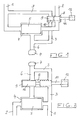
- FIG. 1 schematically illustrated first embodiment of a shower device has a cold water pipe 1 and a hot water pipe 2, which lead to a mixing chamber 4, in which a mixer 5 is arranged.
- the mixer 5 may be a known thermostatic mixer act, which automatically ensures a once set shower water temperature and accordingly the cold water line 1 or hot water line 2 up and heading accordingly. From the mixing chamber 4, the hot water set via the mixer 5 passes via a mixed water line 6 to a shower head shown schematically at 7.
- the user sets a hot water temperature, which is maintained via the thermostatic mixer 5.
- cold water flow via the cold water line 1 and hot water via the hot water line 2 into the mixing chamber 4 and are mixed accordingly.
- FIG. 1 shower device shown also has a magnetic slide valve 9, which has a valve member 10 and a valve rod 11 which is reciprocated via a suitable actuator (solenoid) in a valve chamber 8.
- the valve chamber 8 is passed from the hot water line 2 and a bypass line 3, which branches off from the cold water line 1 and leads directly into the mixed water line 6, bypassing the mixer 5.
- the magnetic sliding valve 9 is formed so that the valve element 10 in a first position of the valve, which in FIG. 1 is shown, the bypass line 3 blocks and the hot water line 2 opens, and in a second position (in FIG. 1 shown in dashed lines), the hot water line 2 blocks and the bypass line 3 opens.
- valve element 10 blocks the bypass line 3, so that the mixing chamber 4 is supplied with hot water via the hot water line 2 unhindered can. If the shower head 7 is to be supplied only with cold water, the valve element 10 is in the in FIG. 1 dashed shown position moves in which the hot water pipe 2 is locked. In this case, cold water passes via the bypass line 3 directly into the mixed water line 6 to the shower head. 7
- the magnetic slide valve 9 is reciprocated at appropriate intervals by the actuator 12. These intervals may be suitably preset (programmed) so that the actuator 12 closes and opens the hot water pipe 2 accordingly. In order to perform such a change shower operation, therefore, only a single valve is required, which alternately opens the hot water pipe 2 and the bypass line 3 and closes.
- the schematically illustrated shower device also has a cold water line 1, a hot water line 2 and a mixing chamber 4 with a thermostatic mixer 5, the cold water line 1 and the hot water line 2 opening into the mixing chamber 4.
- a mixed water line 6 leads to a suitable shower head 7.
- a bypass line 3 which leads bypassing the mixer 5 directly into the mixing water line 6. Cold water can thus be fed directly to the shower head 7, bypassing the mixer, via this line.
- a solenoid slide valve 9 is provided, which is arranged in a suitable valve chamber 8 and a valve element 10 and a valve rod 11 which is pushed via a suitable actuator 12 (an electromagnet) in the valve chamber 8 back and forth.
- the solenoid slide valve 9 In the in FIG. 2 shown position, the solenoid slide valve 9 is in a position in which it blocks the mixed water pipe 6. In this position, therefore, cold water can be fed from the cold water pipe 1 via the bypass line 3 directly into the mixed water pipe 6 and the shower head 7.
- the valve member 10 blocks the bypass line 3, so that hot water can be discharged from the thermostatic mixer via the mixed water line 6 to the shower head 7.
- the magnetic slide valve 9 does not block the hot water line 2, but the mixed water line 6 downstream of the thermostatic mixer. Also, in this embodiment, only a single valve is required to allow a kannuschuschbericht in which alternately the shower head is supplied with hot water and cold water.
- the slide valve provided according to the invention, preferably very short intervals can be achieved, for example cold water intervals which are less than 1 second.
- the actuating element for the slide valve is preferably actuated by battery operation.
Landscapes
- Health & Medical Sciences (AREA)
- Life Sciences & Earth Sciences (AREA)
- Engineering & Computer Science (AREA)
- Hydrology & Water Resources (AREA)
- Public Health (AREA)
- Water Supply & Treatment (AREA)
- Bathtubs, Showers, And Their Attachments (AREA)
- Domestic Plumbing Installations (AREA)
- Multiple-Way Valves (AREA)
Applications Claiming Priority (1)
| Application Number | Priority Date | Filing Date | Title |
|---|---|---|---|
| DE200820009695 DE202008009695U1 (de) | 2008-07-19 | 2008-07-19 | Duscheinrichtung |
Publications (2)
| Publication Number | Publication Date |
|---|---|
| EP2146011A2 true EP2146011A2 (fr) | 2010-01-20 |
| EP2146011A3 EP2146011A3 (fr) | 2012-11-07 |
Family
ID=39877603
Family Applications (1)
| Application Number | Title | Priority Date | Filing Date |
|---|---|---|---|
| EP09008645A Withdrawn EP2146011A3 (fr) | 2008-07-19 | 2009-07-02 | Dispositif de douche |
Country Status (2)
| Country | Link |
|---|---|
| EP (1) | EP2146011A3 (fr) |
| DE (1) | DE202008009695U1 (fr) |
Cited By (5)
| Publication number | Priority date | Publication date | Assignee | Title |
|---|---|---|---|---|
| WO2012123121A1 (fr) | 2011-03-15 | 2012-09-20 | Aquis Sanitär AG | Robinetterie sanitaire pourvue d'un boîtier de robinetterie et d'une unité de contrôle |
| DE102012013594A1 (de) | 2012-07-07 | 2014-01-09 | Bernt Westarp | Leitungssystem zum Transport von Flüssigkeiten |
| WO2014008880A2 (fr) | 2012-07-07 | 2014-01-16 | Bernt Westarp | Système de conduites pour le transport de liquides |
| DE102013009590A1 (de) | 2013-06-07 | 2014-12-11 | Bernt Westarp | Leitungssystem mit vereinfachtem Aufbau |
| DE102017105050A1 (de) | 2017-03-09 | 2018-09-13 | Oras Oy | Wasserbehandlungssystem, Verfahren zur Steuerung einer Wassertemperatur und ein Prozessor |
Citations (1)
| Publication number | Priority date | Publication date | Assignee | Title |
|---|---|---|---|---|
| DE19501716A1 (de) | 1995-01-20 | 1996-07-25 | Grohe Kg Hans | Sanitäre Brauseeinrichtung |
Family Cites Families (3)
| Publication number | Priority date | Publication date | Assignee | Title |
|---|---|---|---|---|
| DE20207365U1 (de) * | 2002-05-08 | 2002-08-01 | Dröber, Sebastian, 22587 Hamburg | Heiß-Kalt-Dusche |
| ITTO20040893A1 (it) * | 2004-12-22 | 2005-03-22 | Gevipi Ag | Dispositivo perfezionato per l'esecuzione di docce a temperature alternate |
| DE202008003652U1 (de) * | 2008-03-14 | 2008-07-03 | Westarp, Bernt | Duscheinrichtung |
-
2008
- 2008-07-19 DE DE200820009695 patent/DE202008009695U1/de not_active Expired - Lifetime
-
2009
- 2009-07-02 EP EP09008645A patent/EP2146011A3/fr not_active Withdrawn
Patent Citations (1)
| Publication number | Priority date | Publication date | Assignee | Title |
|---|---|---|---|---|
| DE19501716A1 (de) | 1995-01-20 | 1996-07-25 | Grohe Kg Hans | Sanitäre Brauseeinrichtung |
Cited By (8)
| Publication number | Priority date | Publication date | Assignee | Title |
|---|---|---|---|---|
| WO2012123121A1 (fr) | 2011-03-15 | 2012-09-20 | Aquis Sanitär AG | Robinetterie sanitaire pourvue d'un boîtier de robinetterie et d'une unité de contrôle |
| EP2686495B1 (fr) | 2011-03-15 | 2024-09-18 | Aquis Sanitär AG | Robinetterie sanitaire pourvue d'un boîtier de robinetterie et d'une unité de contrôle |
| DE102012013594A1 (de) | 2012-07-07 | 2014-01-09 | Bernt Westarp | Leitungssystem zum Transport von Flüssigkeiten |
| WO2014008880A2 (fr) | 2012-07-07 | 2014-01-16 | Bernt Westarp | Système de conduites pour le transport de liquides |
| WO2014008880A3 (fr) * | 2012-07-07 | 2015-03-26 | Bernt Westarp | Système de conduites pour le transport de liquides |
| DE102013009590A1 (de) | 2013-06-07 | 2014-12-11 | Bernt Westarp | Leitungssystem mit vereinfachtem Aufbau |
| DE102017105050A1 (de) | 2017-03-09 | 2018-09-13 | Oras Oy | Wasserbehandlungssystem, Verfahren zur Steuerung einer Wassertemperatur und ein Prozessor |
| EP3385460A1 (fr) * | 2017-03-09 | 2018-10-10 | Oras Oy | Système de traitement de l'eau ; procédé pour réguler une température d'eau et processeur |
Also Published As
| Publication number | Publication date |
|---|---|
| EP2146011A3 (fr) | 2012-11-07 |
| DE202008009695U1 (de) | 2008-10-23 |
Similar Documents
| Publication | Publication Date | Title |
|---|---|---|
| DE2450094A1 (de) | Schieber | |
| DE69718317T2 (de) | Verbesserte Ventilanordnung für Heizsysteme und Wasserheizgeräte | |
| DE102012013594A1 (de) | Leitungssystem zum Transport von Flüssigkeiten | |
| DE202008009695U1 (de) | Duscheinrichtung | |
| EP3149369B1 (fr) | Cartouche de commande réalisée sous la forme d'une vanne anti-brûlure | |
| EP1248173A1 (fr) | Mélangeur thermostatic | |
| EP2870393B1 (fr) | Système de conduites pour le transport de liquides | |
| DE1698057B2 (de) | Vorrichtung zum mischen von fluiden | |
| EP1218630A2 (fr) | Soupape d'injection, en particulier pour systemes d'injection a rampe commune | |
| EP0278333B1 (fr) | Dispositif de commande pour un séparateur de tuyau | |
| EP2206939B1 (fr) | Armature | |
| EP2000714A2 (fr) | Ensemble de soupapes à liquides | |
| DE69715199T2 (de) | Ventilanordnung für Heizsysteme und Wasserheizgeräte und Verfahren zu ihrer Herstellung | |
| DE102016014718A1 (de) | Ventilmodul für einen Ölkreislauf einer Verbrennungskraftmaschine | |
| DE202006005303U1 (de) | Intervallschalteinrichtung für eine Dusche sowie Wechseldusche | |
| EP1039189B1 (fr) | Dispositif de commande d'un organe de commutation | |
| DE10202560A1 (de) | Thermostat-Mischventil | |
| DE7428678U (de) | Druckschaltventil | |
| DE102010062754A1 (de) | Sanitäre Ventileinrichtung | |
| EP1193434B1 (fr) | Soupape, en particulier soupape de radiateur | |
| DE1698057C3 (de) | Vorrichtung zum Mischen von Fluiden | |
| DE202008003652U1 (de) | Duscheinrichtung | |
| DE2532369A1 (de) | Eingriffmischbatterie | |
| EP4286613A1 (fr) | Robinetterie sanitaire | |
| DE102013009590A1 (de) | Leitungssystem mit vereinfachtem Aufbau |
Legal Events
| Date | Code | Title | Description |
|---|---|---|---|
| PUAI | Public reference made under article 153(3) epc to a published international application that has entered the european phase |
Free format text: ORIGINAL CODE: 0009012 |
|
| AK | Designated contracting states |
Kind code of ref document: A2 Designated state(s): AT BE BG CH CY CZ DE DK EE ES FI FR GB GR HR HU IE IS IT LI LT LU LV MC MK MT NL NO PL PT RO SE SI SK SM TR |
|
| AX | Request for extension of the european patent |
Extension state: AL BA RS |
|
| PUAL | Search report despatched |
Free format text: ORIGINAL CODE: 0009013 |
|
| AK | Designated contracting states |
Kind code of ref document: A3 Designated state(s): AT BE BG CH CY CZ DE DK EE ES FI FR GB GR HR HU IE IS IT LI LT LU LV MC MK MT NL NO PL PT RO SE SI SK SM TR |
|
| AX | Request for extension of the european patent |
Extension state: AL BA RS |
|
| RIC1 | Information provided on ipc code assigned before grant |
Ipc: E03C 1/04 20060101AFI20121003BHEP |
|
| STAA | Information on the status of an ep patent application or granted ep patent |
Free format text: STATUS: THE APPLICATION IS DEEMED TO BE WITHDRAWN |
|
| 18D | Application deemed to be withdrawn |
Effective date: 20130508 |