EP2146091A2 - Eolienne - Google Patents
Eolienne Download PDFInfo
- Publication number
- EP2146091A2 EP2146091A2 EP09009058A EP09009058A EP2146091A2 EP 2146091 A2 EP2146091 A2 EP 2146091A2 EP 09009058 A EP09009058 A EP 09009058A EP 09009058 A EP09009058 A EP 09009058A EP 2146091 A2 EP2146091 A2 EP 2146091A2
- Authority
- EP
- European Patent Office
- Prior art keywords
- wing
- outer wing
- rotation
- section
- wind turbine
- Prior art date
- Legal status (The legal status is an assumption and is not a legal conclusion. Google has not performed a legal analysis and makes no representation as to the accuracy of the status listed.)
- Withdrawn
Links
- 230000001154 acute effect Effects 0.000 description 2
- 238000010276 construction Methods 0.000 description 2
- 230000005611 electricity Effects 0.000 description 2
- 230000007704 transition Effects 0.000 description 2
- 238000004026 adhesive bonding Methods 0.000 description 1
- 238000005452 bending Methods 0.000 description 1
- 230000015572 biosynthetic process Effects 0.000 description 1
- 230000004941 influx Effects 0.000 description 1
- 239000002184 metal Substances 0.000 description 1
- 238000005494 tarnishing Methods 0.000 description 1
Images


Classifications
-
- F—MECHANICAL ENGINEERING; LIGHTING; HEATING; WEAPONS; BLASTING
- F03—MACHINES OR ENGINES FOR LIQUIDS; WIND, SPRING, OR WEIGHT MOTORS; PRODUCING MECHANICAL POWER OR A REACTIVE PROPULSIVE THRUST, NOT OTHERWISE PROVIDED FOR
- F03D—WIND MOTORS
- F03D3/00—Wind motors with rotation axis substantially perpendicular to the air flow entering the rotor
- F03D3/06—Rotors
- F03D3/061—Rotors characterised by their aerodynamic shape, e.g. aerofoil profiles
-
- F—MECHANICAL ENGINEERING; LIGHTING; HEATING; WEAPONS; BLASTING
- F03—MACHINES OR ENGINES FOR LIQUIDS; WIND, SPRING, OR WEIGHT MOTORS; PRODUCING MECHANICAL POWER OR A REACTIVE PROPULSIVE THRUST, NOT OTHERWISE PROVIDED FOR
- F03D—WIND MOTORS
- F03D3/00—Wind motors with rotation axis substantially perpendicular to the air flow entering the rotor
- F03D3/005—Wind motors with rotation axis substantially perpendicular to the air flow entering the rotor the axis being vertical
-
- F—MECHANICAL ENGINEERING; LIGHTING; HEATING; WEAPONS; BLASTING
- F05—INDEXING SCHEMES RELATING TO ENGINES OR PUMPS IN VARIOUS SUBCLASSES OF CLASSES F01-F04
- F05B—INDEXING SCHEME RELATING TO WIND, SPRING, WEIGHT, INERTIA OR LIKE MOTORS, TO MACHINES OR ENGINES FOR LIQUIDS COVERED BY SUBCLASSES F03B, F03D AND F03G
- F05B2240/00—Components
- F05B2240/20—Rotors
- F05B2240/30—Characteristics of rotor blades, i.e. of any element transforming dynamic fluid energy to or from rotational energy and being attached to a rotor
- F05B2240/301—Cross-section characteristics
-
- Y—GENERAL TAGGING OF NEW TECHNOLOGICAL DEVELOPMENTS; GENERAL TAGGING OF CROSS-SECTIONAL TECHNOLOGIES SPANNING OVER SEVERAL SECTIONS OF THE IPC; TECHNICAL SUBJECTS COVERED BY FORMER USPC CROSS-REFERENCE ART COLLECTIONS [XRACs] AND DIGESTS
- Y02—TECHNOLOGIES OR APPLICATIONS FOR MITIGATION OR ADAPTATION AGAINST CLIMATE CHANGE
- Y02E—REDUCTION OF GREENHOUSE GAS [GHG] EMISSIONS, RELATED TO ENERGY GENERATION, TRANSMISSION OR DISTRIBUTION
- Y02E10/00—Energy generation through renewable energy sources
- Y02E10/70—Wind energy
- Y02E10/74—Wind turbines with rotation axis perpendicular to the wind direction
Definitions
- the invention relates to a wind turbine with a rotatable about a vertical axis of rotation vane assembly comprising at least one center wing and at least one outer wing, the outer wing having a cross section with an axis of rotation facing the inside, an at least partially convexly curved outside, pointing in the direction of rotation rounded head portion and has a rear end portion.
- wind turbines are also known in which the wing assembly rotates about a vertical axis of rotation.
- a wind turbine usually has a height of 2 to 6m and is in particular for the generation of electricity in small consumers, such as private houses, thought and for example from the WO 89/07713 A1 known.
- the in the WO 89/07713 A1 shown wing assembly comprises a centrally disposed to the vertical rotational axis of rotation Central wing with a substantially elliptical cross-section and two outer wings, which are arranged point-symmetrical to the vertical rotation axis of rotation and have a modified drop-shaped cross-section in the manner of an aircraft wing.
- the center wing and the two outer wings are structurally combined to form a jointly rotating unit.
- the rotational movement of the wing assembly is converted by a generator in a conventional manner into electricity.
- the wing assembly When the wind abates or when there is no wind, the wing assembly initially continues to rotate due to inertia until it comes to a standstill at some point. If the wind then refreshes again, the wing assembly should start automatically due to the wind force occurring. In practice, it has been found that the automatic starting of the wing assembly at certain rotational positions does not work or only inadequate. It could be considered to associate the wing assembly with an electric motor which ensures start up after a standstill. However, this is structurally complex and disadvantageous in terms of energy balance.
- the invention has for its object to provide a wind turbine of the type mentioned, in which a tarnishing of the wing assembly from standstill in the wind is reliably ensured.
- the nose portion located on the outside of the cross-section, facing outwards, i. protrudes in the direction away from the axis of rotation, a small force is generated by the wind even at a side influx of the outer wing, which leads to a torque about the axis of rotation and thus causes the wing assembly in rotation. It has been found that a relatively small dimension of the nose portion is sufficient to ensure the start of the wing assembly after a standstill safely.
- the nose portion 10mm protrudes to 100mm and in particular not more than 50mm from the outer surface of the outside of the side wing.
- the outer wing is continuously convexly curved on its outer side in the conventional design.
- the transition from the convexly curved outer side of the outer wing to the nose section can be effected by an angling of the outer surface, but better flow conditions are given when the nose section, in particular, merges continuously over a concave surface area into the convex outer side of the outer wing.
- the outer wing of known construction tapers in its cross section to the rear end and runs at this either pointed or is rounded there with a small radius.
- a storage area is formed, which preferably not convex rounded, but at least in sections is just designed to give the incoming wind an attack surface.
- the storage area should preferably have a radial width, in the direction perpendicular to the axis of rotation of at least 20mm. It has proven to be useful if the storage area has a radial width in the range of 20mm to 100mm and in particular in the range of 20mm to 50mm.
- the nose portion may be integrally formed in the outside of the outer wing forming sheet metal or profile.
- the nose portion is formed by a strip-shaped extension, which is placed on the outside of the outer wing and fixed there.
- the attachment can be achieved by screwing, gluing or locking.
- the strip-shaped endpiece may be that it is positively engaged with the outer wing.
- the outer wing may have molded longitudinal grooves, in which the extension piece is inserted or inserted with corresponding engagement projections.
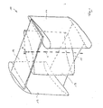
- Fig. 1 shows the basic structure of a wind turbine with a vertical axis of rotation V.
- the wind turbine comprises a wing assembly 10 which is rotatable about the vertical axis of rotation V and two outer wings 11 and 12, which are arranged on opposite sides at a distance from the rotational axis of rotation V and with respect to this point-symmetrical ,
- Each outer wing 11 and 12 has a constant over its height cross section in the manner of a modified teardrop-shaped profile similar to the cross section of an aircraft wing.
- the wider cross-sectional portions of the outer wings 11 and 12 have in opposite horizontal directions.
- a center wing 13 is arranged, which also has a constant over its height cross section and centric to the rotational axis of rotation V is arranged.
- the center wing 13 is aligned so that its longer main axis of rotation is aligned at an angle of approximately 45 ° to a center of the cross sections of the outer wings 11 and 12 connecting straight lines.
- the center wing 13 and the outer wings 11 and 12 are connected on its underside by a support structure, for example in the form of a bottom plate 15 and on its upper side by another support structure, for example in the form of a ceiling plate 14 to a one-piece unit, which as a unit about the vertical rotation axis of rotation V is rotatable as indicated by the arrow D in Fig. 1 is indicated.
- a support structure for example in the form of a bottom plate 15 and on its upper side by another support structure, for example in the form of a ceiling plate 14 to a one-piece unit, which as a unit about the vertical rotation axis of rotation V is rotatable as indicated by the arrow D in Fig. 1 is indicated.
- Fig. 2 shows the cross section of the outer wing 11. This has an inner side 16 which faces the rotational axis of rotation V and extends either straight or slightly concave curved. On the outer, the rotational axis of rotation V opposite outer side 17 of the outer wing 11 has a convexly curved shape. The inner side 16 and the outer side 17 are connected to each other at the front end, which points in the direction of rotation, via a convexly rounded head section 18.
- Fig. 3 shows the dashed projection lines P, which indicate the course of the outer side 17 and the inner side 16, if they were continued while maintaining their curvatures and would meet at a point S.
- the convex outer surface 17 merges into a nose portion 20 near the rear end of the outer wing 11 by means of a concave surface region 22 deflection, with the projecting protrusion formed thereby Nose wall 20a of the outside 17 is outside the fictitious cross section defined by the projection lines P.
- the inner side 16 is guided near its rear end over a bend 26 in the direction of the nose wall 20a and meets at an acute angle, for example at 90 ° to this, whereby at the lower end of the outer wing 11, a storage area 21 is formed.
- the nose portion 20 is integral with the walls of the outer wing 11 by bending and joining the respective panels or trim panels to form the nose portion 20.
- Fig. 4 shows an alternative embodiment in which the nose portion 20 can be subsequently attached to the outer wing 11.
- the outer wing 11 according to Fig. 4 has initially at the lower end a continuously tapering, tapered cross-section, which is bounded by the concave inner side 16 and the convex outer side 17.
- a strip-shaped extension piece 23 is attached via fastening means 24.
- the strip-shaped extension piece 23 extends over the entire height of the outer wing 11 and forms the nose portion 20.
- the extension piece 23 has a triangular cross section, so that between the outside of the extension piece 23 and the outer side 17 of the outer wing 11 on the surface of a outwardly directed bend 27 is formed.
- the rear end of the outer wing 11 facing leg of the cross section of the extension piece 23 forms the rear storage area 21st
- Fig. 5 shows an alternative attachment of the strip-shaped extension piece 23 on the outer wing 11.
- a plurality of provided with an undercut engagement grooves 25 are formed in the outer wing 11 both on its outer side 17 and at the lower end or on the inner side 16, in which the extension piece 23rd can be introduced with corresponding projections 28, whereby the extension piece 23 is positively mounted on the outer wing 11.
- the extension piece 23 is also formed with a substantially triangular cross-section, so that on the outer surface of the outer wing 11 an angled transition 27 between its outer side 17 and the outer side of the extension piece 23 is formed.
- the storage area 21 is formed in the aforementioned manner.
- the nose portion 20 may be sufficient to form the nose portion 20 with very small dimensions.
- a corresponding embodiment is in Fig. 6 shown.
- the projection lines P of the inner side 16 and the convex outer side 17 of the outer wing 11 are shown.
- the convex profile of the outer side 17 merges into a slightly concave surface region 22, so that the outer side 17 between the concave surface portion 22 and the rear end of the outer wing 11 by a small amount outside the projection line P of convex course of the outside 17 runs.
- This outside of the projection line P lying portion of the outer side 17 forms the nose portion 20.
- the storage area 21 is formed, which is connected to both the inner side 16 and the outer side 17 of the outer wing 11, for example, at an acute angle.
Landscapes
- Engineering & Computer Science (AREA)
- Life Sciences & Earth Sciences (AREA)
- Sustainable Development (AREA)
- Sustainable Energy (AREA)
- Chemical & Material Sciences (AREA)
- Combustion & Propulsion (AREA)
- Mechanical Engineering (AREA)
- General Engineering & Computer Science (AREA)
- Physics & Mathematics (AREA)
- Fluid Mechanics (AREA)
- Wind Motors (AREA)
- Structures Of Non-Positive Displacement Pumps (AREA)
Applications Claiming Priority (1)
| Application Number | Priority Date | Filing Date | Title |
|---|---|---|---|
| DE102008033532A DE102008033532A1 (de) | 2008-07-17 | 2008-07-17 | Windkraftanlage |
Publications (2)
| Publication Number | Publication Date |
|---|---|
| EP2146091A2 true EP2146091A2 (fr) | 2010-01-20 |
| EP2146091A3 EP2146091A3 (fr) | 2013-08-21 |
Family
ID=41017182
Family Applications (1)
| Application Number | Title | Priority Date | Filing Date |
|---|---|---|---|
| EP09009058.0A Withdrawn EP2146091A3 (fr) | 2008-07-17 | 2009-07-10 | Eolienne |
Country Status (2)
| Country | Link |
|---|---|
| EP (1) | EP2146091A3 (fr) |
| DE (1) | DE102008033532A1 (fr) |
Cited By (1)
| Publication number | Priority date | Publication date | Assignee | Title |
|---|---|---|---|---|
| WO2011045820A1 (fr) * | 2009-10-13 | 2011-04-21 | Roberto Bolelli | Ensemble de conversion d'énergie |
Citations (1)
| Publication number | Priority date | Publication date | Assignee | Title |
|---|---|---|---|---|
| WO1989007713A1 (fr) | 1988-02-18 | 1989-08-24 | Alfred Goedecke | Eolienne |
Family Cites Families (4)
| Publication number | Priority date | Publication date | Assignee | Title |
|---|---|---|---|---|
| GB8530580D0 (en) * | 1985-12-12 | 1986-01-22 | Vannan J N | Fluid mill |
| WO1995008061A2 (fr) * | 1993-09-06 | 1995-03-23 | Shioshvili Tamaz J | Dispositif de reception de l'energie eolienne 'shio-9' |
| DE4401926C2 (de) * | 1994-01-24 | 1998-02-05 | Wolfgang Klaus | Rotor für Windkraftanlage |
| ITBZ20040007A1 (it) * | 2004-03-02 | 2004-06-02 | Ropatec Spa | Motore a vento con rotore ad asse di rotazione verticale e corpo deflettore centrale |
-
2008
- 2008-07-17 DE DE102008033532A patent/DE102008033532A1/de not_active Withdrawn
-
2009
- 2009-07-10 EP EP09009058.0A patent/EP2146091A3/fr not_active Withdrawn
Patent Citations (1)
| Publication number | Priority date | Publication date | Assignee | Title |
|---|---|---|---|---|
| WO1989007713A1 (fr) | 1988-02-18 | 1989-08-24 | Alfred Goedecke | Eolienne |
Cited By (1)
| Publication number | Priority date | Publication date | Assignee | Title |
|---|---|---|---|---|
| WO2011045820A1 (fr) * | 2009-10-13 | 2011-04-21 | Roberto Bolelli | Ensemble de conversion d'énergie |
Also Published As
| Publication number | Publication date |
|---|---|
| DE102008033532A1 (de) | 2010-01-21 |
| EP2146091A3 (fr) | 2013-08-21 |
Similar Documents
| Publication | Publication Date | Title |
|---|---|---|
| EP2920460B1 (fr) | Extrémité de pale de rotor et procedé de fabrication pour celle-ci | |
| EP2788618B1 (fr) | Caisson arrière, pale de rotor avec caisson arrière et éolienne équipée d'une pale de rotor | |
| EP3120017B1 (fr) | Pale de rotor d'éolienne équipée d'un raccord de pale de rotor et procédé de fabrication | |
| DE102013110495A1 (de) | Übergangskörper zwischen Turmabschnitten einer Windkraftanlage und Turm einer Windkraftanlage umfassend einen Übergangskörper | |
| EP3455493B1 (fr) | Pale de rotor d'éolienne et éolienne équipée de cette dernière | |
| WO2008003389A1 (fr) | Moyeu de rotor d'une éolienne | |
| DE102017125060A1 (de) | Ringförmige Konsole zum externen Spannen eines Turmsegments, externes Spannsystem eines Hybridturms, Turmabschnitt eines Hybridturms, Hybridturm, Windenergieanlage und Montageverfahren eines externen Spannsystems für einen Hybridturm | |
| DE10152550A1 (de) | Bauelement | |
| EP3129644B1 (fr) | Pale de rotor d'une éolienne | |
| EP2098723A2 (fr) | Rotor optimisé pour une éolienne et montage d'une telle éolienne sur un bâtiment | |
| EP2840255B1 (fr) | Profil d'une pale de rotor d'une éolienne | |
| EP3824176B1 (fr) | Pale de rotor pour éolienne et éolienne | |
| WO2019020464A1 (fr) | Partie de tour en acier pour éoliennes, pour une tour d'éolienne et procédé pour la produire | |
| DE102009007812B4 (de) | Windkraftanlage mit windschlüpfiger Profilierung | |
| DE102013011245B4 (de) | Befestigungssystem für strangförmige Elemente, insbesondere Kabel bei Windkraftanlagen | |
| EP3399183B1 (fr) | Pale de rotor d'une éolienne | |
| EP2146092A2 (fr) | Eolienne | |
| DE202013105408U1 (de) | Masteinrichtung für eine Windenergieanlage | |
| EP2236693B1 (fr) | Support à isolation thermique pour éléments de revêtement | |
| EP3844384B1 (fr) | Rotor comprenant une pale de rotor, éolienne et procédé d'optimisation d'une éolienne | |
| DE102008033532A1 (de) | Windkraftanlage | |
| EP3604796A1 (fr) | Pale de rotor pour une éolienne, éolienne, procédé d'extension d'une pale de rotor ainsi que procédé de fabrication d'une pale de rotor | |
| DE102007017942A1 (de) | Windkraftanlage | |
| EP3927966B1 (fr) | Segment annulaire de tour en acier pour une partie de tour d'éolienne et procédé | |
| DE102008051297B3 (de) | Rotorblatt einer Windkraftanlage |
Legal Events
| Date | Code | Title | Description |
|---|---|---|---|
| PUAI | Public reference made under article 153(3) epc to a published international application that has entered the european phase |
Free format text: ORIGINAL CODE: 0009012 |
|
| AK | Designated contracting states |
Kind code of ref document: A2 Designated state(s): AT BE BG CH CY CZ DE DK EE ES FI FR GB GR HR HU IE IS IT LI LT LU LV MC MK MT NL NO PL PT RO SE SI SK SM TR |
|
| AX | Request for extension of the european patent |
Extension state: AL BA RS |
|
| PUAL | Search report despatched |
Free format text: ORIGINAL CODE: 0009013 |
|
| AK | Designated contracting states |
Kind code of ref document: A3 Designated state(s): AT BE BG CH CY CZ DE DK EE ES FI FR GB GR HR HU IE IS IT LI LT LU LV MC MK MT NL NO PL PT RO SE SI SK SM TR |
|
| AX | Request for extension of the european patent |
Extension state: AL BA RS |
|
| RIC1 | Information provided on ipc code assigned before grant |
Ipc: F03D 3/06 20060101ALI20130712BHEP Ipc: F03D 3/00 20060101ALI20130712BHEP Ipc: F03D 3/02 20060101AFI20130712BHEP |
|
| 111Z | Information provided on other rights and legal means of execution |
Free format text: AT BE BG CH CY CZ DE DK EE ES FI FR GB GR HR HU IE IS IT LT LU LV MC MK MT NL NO PL PT RO SE SI SK SM TR Effective date: 20101118 |
|
| STAA | Information on the status of an ep patent application or granted ep patent |
Free format text: STATUS: THE APPLICATION IS DEEMED TO BE WITHDRAWN |
|
| 18D | Application deemed to be withdrawn |
Effective date: 20140201 |