EP2146092A2 - Eolienne - Google Patents
Eolienne Download PDFInfo
- Publication number
- EP2146092A2 EP2146092A2 EP09009059A EP09009059A EP2146092A2 EP 2146092 A2 EP2146092 A2 EP 2146092A2 EP 09009059 A EP09009059 A EP 09009059A EP 09009059 A EP09009059 A EP 09009059A EP 2146092 A2 EP2146092 A2 EP 2146092A2
- Authority
- EP
- European Patent Office
- Prior art keywords
- wing
- flange
- rotation
- cross
- section
- Prior art date
- Legal status (The legal status is an assumption and is not a legal conclusion. Google has not performed a legal analysis and makes no representation as to the accuracy of the status listed.)
- Withdrawn
Links
- 239000000945 filler Substances 0.000 claims 1
- 230000007704 transition Effects 0.000 description 2
- 230000001154 acute effect Effects 0.000 description 1
- 230000015572 biosynthetic process Effects 0.000 description 1
- 230000005611 electricity Effects 0.000 description 1
- 230000002349 favourable effect Effects 0.000 description 1
- 239000000499 gel Substances 0.000 description 1
- 238000004519 manufacturing process Methods 0.000 description 1
- 230000004048 modification Effects 0.000 description 1
- 238000012986 modification Methods 0.000 description 1
- 238000005494 tarnishing Methods 0.000 description 1
Images


Classifications
-
- F—MECHANICAL ENGINEERING; LIGHTING; HEATING; WEAPONS; BLASTING
- F03—MACHINES OR ENGINES FOR LIQUIDS; WIND, SPRING, OR WEIGHT MOTORS; PRODUCING MECHANICAL POWER OR A REACTIVE PROPULSIVE THRUST, NOT OTHERWISE PROVIDED FOR
- F03D—WIND MOTORS
- F03D3/00—Wind motors with rotation axis substantially perpendicular to the air flow entering the rotor
- F03D3/02—Wind motors with rotation axis substantially perpendicular to the air flow entering the rotor having a plurality of rotors
-
- F—MECHANICAL ENGINEERING; LIGHTING; HEATING; WEAPONS; BLASTING
- F03—MACHINES OR ENGINES FOR LIQUIDS; WIND, SPRING, OR WEIGHT MOTORS; PRODUCING MECHANICAL POWER OR A REACTIVE PROPULSIVE THRUST, NOT OTHERWISE PROVIDED FOR
- F03D—WIND MOTORS
- F03D3/00—Wind motors with rotation axis substantially perpendicular to the air flow entering the rotor
- F03D3/06—Rotors
- F03D3/061—Rotors characterised by their aerodynamic shape, e.g. aerofoil profiles
-
- F—MECHANICAL ENGINEERING; LIGHTING; HEATING; WEAPONS; BLASTING
- F05—INDEXING SCHEMES RELATING TO ENGINES OR PUMPS IN VARIOUS SUBCLASSES OF CLASSES F01-F04
- F05B—INDEXING SCHEME RELATING TO WIND, SPRING, WEIGHT, INERTIA OR LIKE MOTORS, TO MACHINES OR ENGINES FOR LIQUIDS COVERED BY SUBCLASSES F03B, F03D AND F03G
- F05B2240/00—Components
- F05B2240/20—Rotors
- F05B2240/21—Rotors for wind turbines
- F05B2240/211—Rotors for wind turbines with vertical axis
- F05B2240/212—Rotors for wind turbines with vertical axis of the Darrieus type
-
- F—MECHANICAL ENGINEERING; LIGHTING; HEATING; WEAPONS; BLASTING
- F05—INDEXING SCHEMES RELATING TO ENGINES OR PUMPS IN VARIOUS SUBCLASSES OF CLASSES F01-F04
- F05B—INDEXING SCHEME RELATING TO WIND, SPRING, WEIGHT, INERTIA OR LIKE MOTORS, TO MACHINES OR ENGINES FOR LIQUIDS COVERED BY SUBCLASSES F03B, F03D AND F03G
- F05B2240/00—Components
- F05B2240/20—Rotors
- F05B2240/21—Rotors for wind turbines
- F05B2240/211—Rotors for wind turbines with vertical axis
- F05B2240/213—Rotors for wind turbines with vertical axis of the Savonius type
-
- F—MECHANICAL ENGINEERING; LIGHTING; HEATING; WEAPONS; BLASTING
- F05—INDEXING SCHEMES RELATING TO ENGINES OR PUMPS IN VARIOUS SUBCLASSES OF CLASSES F01-F04
- F05B—INDEXING SCHEME RELATING TO WIND, SPRING, WEIGHT, INERTIA OR LIKE MOTORS, TO MACHINES OR ENGINES FOR LIQUIDS COVERED BY SUBCLASSES F03B, F03D AND F03G
- F05B2240/00—Components
- F05B2240/20—Rotors
- F05B2240/30—Characteristics of rotor blades, i.e. of any element transforming dynamic fluid energy to or from rotational energy and being attached to a rotor
- F05B2240/301—Cross-section characteristics
-
- F—MECHANICAL ENGINEERING; LIGHTING; HEATING; WEAPONS; BLASTING
- F05—INDEXING SCHEMES RELATING TO ENGINES OR PUMPS IN VARIOUS SUBCLASSES OF CLASSES F01-F04
- F05B—INDEXING SCHEME RELATING TO WIND, SPRING, WEIGHT, INERTIA OR LIKE MOTORS, TO MACHINES OR ENGINES FOR LIQUIDS COVERED BY SUBCLASSES F03B, F03D AND F03G
- F05B2250/00—Geometry
- F05B2250/30—Arrangement of components
- F05B2250/31—Arrangement of components according to the direction of their main axis or their axis of rotation
- F05B2250/314—Arrangement of components according to the direction of their main axis or their axis of rotation the axes being inclined in relation to each other
-
- Y—GENERAL TAGGING OF NEW TECHNOLOGICAL DEVELOPMENTS; GENERAL TAGGING OF CROSS-SECTIONAL TECHNOLOGIES SPANNING OVER SEVERAL SECTIONS OF THE IPC; TECHNICAL SUBJECTS COVERED BY FORMER USPC CROSS-REFERENCE ART COLLECTIONS [XRACs] AND DIGESTS
- Y02—TECHNOLOGIES OR APPLICATIONS FOR MITIGATION OR ADAPTATION AGAINST CLIMATE CHANGE
- Y02E—REDUCTION OF GREENHOUSE GAS [GHG] EMISSIONS, RELATED TO ENERGY GENERATION, TRANSMISSION OR DISTRIBUTION
- Y02E10/00—Energy generation through renewable energy sources
- Y02E10/70—Wind energy
- Y02E10/74—Wind turbines with rotation axis perpendicular to the wind direction
Definitions
- the invention relates to a wind turbine with a rotatable about a vertical axis of rotation wing assembly comprising at least one center wing and at least one outer wing, wherein the center wing has a cross-section with the axis of rotation radially outer ends.
- wind power plants of the aforementioned type are known in which the vane arrangement rotates about a vertical axis.
- a wind turbine usually has a height of 2m to 6m and is intended in particular for the production of electricity in small consumers, such as private homes.
- a corresponding wind turbine is for example in the WO 89/07713 A1 shown.
- the in the WO 89/07713 A1 shown wing assembly comprises a central to the vertical axis of rotation arranged center wing and two outer wings, which are arranged point-symmetrical to the vertical axis of rotation and a modified teardrop-shaped cross-section in the manner of an aircraft wing exhibit.
- the center wing and the two outer wings are structurally combined to form a jointly rotating wing arrangement whose rotary motion is converted by means of a generator in a conventional manner into electrical current.
- the wing arrangement In the event of a waning wind or in the case of calm, the wing arrangement initially continues to rotate due to the inertia of inertia until it comes to a standstill at some point. If the wind then refreshes again, the wing assembly should start automatically due to the wind force occurring. In practice, it has been found that the automatic starting of the wing assembly at certain rotational positions does not work or only insufficient, so that the wind turbine needs an additional start-up, which is structurally complex and disadvantageous.
- the invention has for its object to provide a wind turbine of the type mentioned, in which a tarnishing of the wing assembly from standstill in the wind is reliably ensured.
- the invention is based on the basic idea that form at the end of the center wing relatively large wind vortex or turbulence, which disturb the flow of the essential for the automatic start of the wing assembly outer wings and obstruct.
- the one at the end of the cross section formed of the central wing flange significantly reduces the vortex formation, so that a favorable flow behavior of the wind is achieved on the outer wings, whereby the startup behavior of the wind turbine is substantially improved.
- a respective flange is formed at both radially outer ends of the cross section of the central wing, which preferably extends over the entire height of the central wing.
- the flange may be plate-shaped or plate-like and preferably extends at an acute angle to the connecting line which connects the vertical axis of rotation V and thus the center of the cross section of the central wing to the radially outer end of the central wing.
- the flange is oriented so that it is preferably only on the side facing away from the direction of rotation of the wing assembly of the cross section of the central wing, i. protrudes in the counter-rotating direction.
- the flange forms a bend with the end of the cross section of the center wing, so that the cross section has an edge in this area.
- the flange smoothly and steplessly in the at least on the side facing in the direction of rotation of the wing assembly Surface of the center wing passes. This can be achieved for example by a rounded or rounded transition region.
- FIG. 1 shows the basic structure of a wind turbine with a vertical axis of rotation V, which is perpendicular to the plane of the drawing.
- the wind turbine comprises a vane assembly 10, which is rotatable about the vertical axis of rotation V and has two outer wings 11 and 12 which are arranged on opposite sides at a distance from the axis of rotation V and with respect to this point-symmetrical are.
- Each outer wing 11 and 12 has a constant over its height cross section in the manner of a modified teardrop-shaped profile similar to the cross section of an aircraft wing.
- the wider cross-sectional portions of the outer wings 11 and 12 have in opposite horizontal directions.
- a center wing 13 is arranged, which also has a constant over its height cross-section and is arranged centrally to the axis of rotation V.
- the center wing 13 is aligned so that its longer major axis is aligned at an angle of approximately 45 ° to a center of the cross sections of the outer wings 11 and 12 connecting straight lines.
- the center wing 13 and the outer wings 11 and 12 are connected on its underside by a supporting structure, for example in the form of a bottom plate 14 and on its upper side by another support structure, for example in the form of a (not shown) ceiling plate to a one-piece unit, which as a unit to the vertical axis of rotation V is rotatable, as indicated by the arrow D in FIG. 1 is indicated.
- a supporting structure for example in the form of a bottom plate 14 and on its upper side by another support structure, for example in the form of a (not shown) ceiling plate to a one-piece unit, which as a unit to the vertical axis of rotation V is rotatable, as indicated by the arrow D in FIG. 1 is indicated.
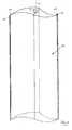
- FIGS. 1 and 2 show the cross section of the center wing 13.
- the cross section of the center wing 13 is point symmetrical to the vertical axis of rotation V and tapers with increasing distance from the axis of rotation V and runs at its two radially outer ends 19 each pointed.
- a laterally projecting flange 16 is integrally formed according to Fig. 2 extends over the entire height of the central wing 13 and over its entire Height has a constant cross-section.
- the flange 16 is plate-shaped or strip-shaped and mounted with one of its longitudinal sides at each end 19 of the cross section of the central wing 13. In this way, it is achieved that the flange 16 only on the side facing away from the direction of rotation D of the wing assembly 10 side, ie protruding in the opposite direction of rotation, as in particular FIG. 1 is apparent.
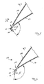
- the center wing 13 has a pointing in the direction of rotation D surface 18 and a direction of rotation D facing away from the surface 17, from which the flange 16 protrudes. With the surface D 17 facing away from the direction of rotation D, the flange 16 encloses an angle .alpha FIG. 3 illustrated embodiment is 90 °. Between the pointing in the direction of rotation D surface 18 and the flange 16, an edge or angling 20 is formed at the end of the cross section of the central wing 13.
- the embodiment according to FIG. 4 differs from the embodiment according to FIG. 3 merely in that the angle formed between the surface D 17 facing away from the direction of rotation D of the central wing 13 and the flange 16 is increased to approximately 135 °.
- the embodiment according to FIG. 5 differs from the embodiment according to FIG. 3 in that the flange 16 is convexly rounded on its outer side facing away from the axis of rotation V and passes smoothly and steplessly in a continuous curve over a convex transitional region 21 into the surface 18 of the central wing pointing in the direction of rotation.
- the flange 16 On its inner side facing the axis of rotation V, the flange 16 is substantially planar and passes over one concave curved transition region 22 in the direction of rotation D facing away from surface 17 of the central wing 13 via.
- the embodiment according to FIG. 6 differs from the embodiment according to FIG. 5 again only in that the angle ⁇ between the flange 16 and the direction D of rotation facing away from the surface 17 of the central wing 13 is increased to 135 °.
Landscapes
- Engineering & Computer Science (AREA)
- Life Sciences & Earth Sciences (AREA)
- Sustainable Development (AREA)
- Sustainable Energy (AREA)
- Chemical & Material Sciences (AREA)
- Combustion & Propulsion (AREA)
- Mechanical Engineering (AREA)
- General Engineering & Computer Science (AREA)
- Physics & Mathematics (AREA)
- Fluid Mechanics (AREA)
- Wind Motors (AREA)
Applications Claiming Priority (1)
| Application Number | Priority Date | Filing Date | Title |
|---|---|---|---|
| DE102008033531A DE102008033531A1 (de) | 2008-07-17 | 2008-07-17 | Windkraftanlage |
Publications (2)
| Publication Number | Publication Date |
|---|---|
| EP2146092A2 true EP2146092A2 (fr) | 2010-01-20 |
| EP2146092A3 EP2146092A3 (fr) | 2013-08-07 |
Family
ID=40996557
Family Applications (1)
| Application Number | Title | Priority Date | Filing Date |
|---|---|---|---|
| EP09009059.8A Withdrawn EP2146092A3 (fr) | 2008-07-17 | 2009-07-10 | Eolienne |
Country Status (2)
| Country | Link |
|---|---|
| EP (1) | EP2146092A3 (fr) |
| DE (1) | DE102008033531A1 (fr) |
Cited By (4)
| Publication number | Priority date | Publication date | Assignee | Title |
|---|---|---|---|---|
| DE4416253B4 (de) | 1994-05-07 | 2005-09-22 | Deutsche Telekom Ag | Verfahren zur datenschutzgerechten Verteilung von Schlüsselinformationen |
| WO2011045820A1 (fr) * | 2009-10-13 | 2011-04-21 | Roberto Bolelli | Ensemble de conversion d'énergie |
| CN107747530A (zh) * | 2017-12-05 | 2018-03-02 | 许占欣 | 一种风洞式垂直轴风力发电机风轮装置 |
| EP3342480A1 (fr) * | 2016-12-27 | 2018-07-04 | Zeppelin Systems GmbH | Outil de mélange pour un mélangeur et mélangeur |
Citations (1)
| Publication number | Priority date | Publication date | Assignee | Title |
|---|---|---|---|---|
| WO1989007713A1 (fr) | 1988-02-18 | 1989-08-24 | Alfred Goedecke | Eolienne |
Family Cites Families (5)
| Publication number | Priority date | Publication date | Assignee | Title |
|---|---|---|---|---|
| DE604333C (fr) * | ||||
| GB2097481B (en) * | 1981-04-25 | 1984-05-31 | Store Roland | Wind or water-powered rotor blade |
| GB8530580D0 (en) * | 1985-12-12 | 1986-01-22 | Vannan J N | Fluid mill |
| DE4401926C2 (de) * | 1994-01-24 | 1998-02-05 | Wolfgang Klaus | Rotor für Windkraftanlage |
| DE202006013779U1 (de) * | 2006-09-08 | 2008-01-24 | AeroVigor Hungária Kft. | Windkraftanlage |
-
2008
- 2008-07-17 DE DE102008033531A patent/DE102008033531A1/de not_active Withdrawn
-
2009
- 2009-07-10 EP EP09009059.8A patent/EP2146092A3/fr not_active Withdrawn
Patent Citations (1)
| Publication number | Priority date | Publication date | Assignee | Title |
|---|---|---|---|---|
| WO1989007713A1 (fr) | 1988-02-18 | 1989-08-24 | Alfred Goedecke | Eolienne |
Cited By (4)
| Publication number | Priority date | Publication date | Assignee | Title |
|---|---|---|---|---|
| DE4416253B4 (de) | 1994-05-07 | 2005-09-22 | Deutsche Telekom Ag | Verfahren zur datenschutzgerechten Verteilung von Schlüsselinformationen |
| WO2011045820A1 (fr) * | 2009-10-13 | 2011-04-21 | Roberto Bolelli | Ensemble de conversion d'énergie |
| EP3342480A1 (fr) * | 2016-12-27 | 2018-07-04 | Zeppelin Systems GmbH | Outil de mélange pour un mélangeur et mélangeur |
| CN107747530A (zh) * | 2017-12-05 | 2018-03-02 | 许占欣 | 一种风洞式垂直轴风力发电机风轮装置 |
Also Published As
| Publication number | Publication date |
|---|---|
| EP2146092A3 (fr) | 2013-08-07 |
| DE102008033531A1 (de) | 2010-01-21 |
Similar Documents
| Publication | Publication Date | Title |
|---|---|---|
| DE10347802B3 (de) | Rotorblatt für eine Windkraftanlage | |
| DE112012005432T5 (de) | Windturbine mit Gondelzaun | |
| DE102012104317A1 (de) | Rotorklappe für ein Rotorblatt in einer Windturbine | |
| EP2840255B1 (fr) | Profil d'une pale de rotor d'une éolienne | |
| DE102013207640A1 (de) | Windenergieanlagen-Rotorblatt | |
| DE202011003442U1 (de) | Vorrichtung zur Nutzung von Windkraft mit mindestens einem Rotor | |
| DE202009009654U1 (de) | Windkraftanlage | |
| DE102008033531A1 (de) | Windkraftanlage | |
| DE102016108338A1 (de) | Windkraftanlage | |
| DE102009007812B4 (de) | Windkraftanlage mit windschlüpfiger Profilierung | |
| EP2555969B1 (fr) | Navire à plaque réglable à la proue | |
| DE202013105408U1 (de) | Masteinrichtung für eine Windenergieanlage | |
| DE102009010905A1 (de) | Windkraftanlage | |
| EP3399183A1 (fr) | Pale de rotor d'une éolienne | |
| EP3969743A1 (fr) | Pale de rotor et éolienne | |
| DE102021203274A1 (de) | Windradrotorblattbaugruppe und Windrad | |
| EP2146091A2 (fr) | Eolienne | |
| DE102010016086A1 (de) | Rotorblatt für H-Rotor | |
| EP3954892A2 (fr) | Pale de rotor pour une éolienne, rotor pour une éolienne, construction et éolienne | |
| DE102016110295B4 (de) | Windenergieanlage mit einem ein aerodynamisches Profil mit einem spiegelsymmetrischen Querschnitt aufweisenden Turm | |
| DE202017106237U1 (de) | Windkraftanlage zur Umwandlung von Windenergie in mechanische und elektrische Energie sowie Land- oder Wasserfahrzeug mit einer solchen Windkraftanlage als Antrieb | |
| DE19835958B4 (de) | Durch Windkraft antreibbarer Rotor | |
| EP3546033A1 (fr) | Appareil et procede pour generer un fort ecoulement dans une piscine | |
| DE102011050462A1 (de) | Windkraftanlage | |
| DE102014100382A1 (de) | Rotor für eine Wind- oder Wasserkraftanlage |
Legal Events
| Date | Code | Title | Description |
|---|---|---|---|
| PUAI | Public reference made under article 153(3) epc to a published international application that has entered the european phase |
Free format text: ORIGINAL CODE: 0009012 |
|
| AK | Designated contracting states |
Kind code of ref document: A2 Designated state(s): AT BE BG CH CY CZ DE DK EE ES FI FR GB GR HR HU IE IS IT LI LT LU LV MC MK MT NL NO PL PT RO SE SI SK SM TR |
|
| AX | Request for extension of the european patent |
Extension state: AL BA RS |
|
| PUAL | Search report despatched |
Free format text: ORIGINAL CODE: 0009013 |
|
| RIC1 | Information provided on ipc code assigned before grant |
Ipc: F03D 3/02 20060101AFI20130627BHEP Ipc: F03D 3/06 20060101ALI20130627BHEP |
|
| AK | Designated contracting states |
Kind code of ref document: A3 Designated state(s): AT BE BG CH CY CZ DE DK EE ES FI FR GB GR HR HU IE IS IT LI LT LU LV MC MK MT NL NO PL PT RO SE SI SK SM TR |
|
| AX | Request for extension of the european patent |
Extension state: AL BA RS |
|
| 111Z | Information provided on other rights and legal means of execution |
Free format text: AT BE BG CH CY CZ DE DK EE ES FI FR GB GR HR HU IE IS IT LT LU LV MC MK MT NL NO PL PT RO SE SI SK SM TR Effective date: 20101118 |
|
| STAA | Information on the status of an ep patent application or granted ep patent |
Free format text: STATUS: THE APPLICATION IS DEEMED TO BE WITHDRAWN |
|
| 18D | Application deemed to be withdrawn |
Effective date: 20140201 |