EP2146096A2 - Pompe à palettes - Google Patents
Pompe à palettes Download PDFInfo
- Publication number
- EP2146096A2 EP2146096A2 EP09009171A EP09009171A EP2146096A2 EP 2146096 A2 EP2146096 A2 EP 2146096A2 EP 09009171 A EP09009171 A EP 09009171A EP 09009171 A EP09009171 A EP 09009171A EP 2146096 A2 EP2146096 A2 EP 2146096A2
- Authority
- EP
- European Patent Office
- Prior art keywords
- rotary unit
- casing
- annular chamber
- pump
- pump chambers
- Prior art date
- Legal status (The legal status is an assumption and is not a legal conclusion. Google has not performed a legal analysis and makes no representation as to the accuracy of the status listed.)
- Withdrawn
Links
- 239000012530 fluid Substances 0.000 claims abstract description 49
- 238000011144 upstream manufacturing Methods 0.000 claims description 3
- 239000000758 substrate Substances 0.000 description 12
- 230000009467 reduction Effects 0.000 description 10
- 239000000696 magnetic material Substances 0.000 description 5
- 230000002093 peripheral effect Effects 0.000 description 5
- 238000000926 separation method Methods 0.000 description 5
- 239000000463 material Substances 0.000 description 4
- 230000005415 magnetization Effects 0.000 description 3
- 230000008859 change Effects 0.000 description 2
- 238000005260 corrosion Methods 0.000 description 2
- 230000007797 corrosion Effects 0.000 description 2
- 238000007599 discharging Methods 0.000 description 2
- 238000005192 partition Methods 0.000 description 2
- 239000011347 resin Substances 0.000 description 2
- 229920005989 resin Polymers 0.000 description 2
- 230000008878 coupling Effects 0.000 description 1
- 238000010168 coupling process Methods 0.000 description 1
- 238000005859 coupling reaction Methods 0.000 description 1
- 239000007788 liquid Substances 0.000 description 1
- 239000012762 magnetic filler Substances 0.000 description 1
- 238000004519 manufacturing process Methods 0.000 description 1
- 229910052751 metal Inorganic materials 0.000 description 1
- 239000002184 metal Substances 0.000 description 1
- 230000035699 permeability Effects 0.000 description 1
- 238000003825 pressing Methods 0.000 description 1
- 238000005096 rolling process Methods 0.000 description 1
- 229910000938 samarium–cobalt magnet Inorganic materials 0.000 description 1
- 229910001220 stainless steel Inorganic materials 0.000 description 1
- 239000010935 stainless steel Substances 0.000 description 1
- 230000008961 swelling Effects 0.000 description 1
- 239000013585 weight reducing agent Substances 0.000 description 1
- 229910000859 α-Fe Inorganic materials 0.000 description 1
Images


Classifications
-
- F—MECHANICAL ENGINEERING; LIGHTING; HEATING; WEAPONS; BLASTING
- F04—POSITIVE - DISPLACEMENT MACHINES FOR LIQUIDS; PUMPS FOR LIQUIDS OR ELASTIC FLUIDS
- F04C—ROTARY-PISTON, OR OSCILLATING-PISTON, POSITIVE-DISPLACEMENT MACHINES FOR LIQUIDS; ROTARY-PISTON, OR OSCILLATING-PISTON, POSITIVE-DISPLACEMENT PUMPS
- F04C18/00—Rotary-piston pumps specially adapted for elastic fluids
- F04C18/30—Rotary-piston pumps specially adapted for elastic fluids having the characteristics covered by two or more of groups F04C18/02, F04C18/08, F04C18/22, F04C18/24, F04C18/48, or having the characteristics covered by one of these groups together with some other type of movement between co-operating members
- F04C18/34—Rotary-piston pumps specially adapted for elastic fluids having the characteristics covered by two or more of groups F04C18/02, F04C18/08, F04C18/22, F04C18/24, F04C18/48, or having the characteristics covered by one of these groups together with some other type of movement between co-operating members having the movement defined in group F04C18/08 or F04C18/22 and relative reciprocation between the co-operating members
- F04C18/344—Rotary-piston pumps specially adapted for elastic fluids having the characteristics covered by two or more of groups F04C18/02, F04C18/08, F04C18/22, F04C18/24, F04C18/48, or having the characteristics covered by one of these groups together with some other type of movement between co-operating members having the movement defined in group F04C18/08 or F04C18/22 and relative reciprocation between the co-operating members with vanes reciprocating with respect to the inner member
-
- F—MECHANICAL ENGINEERING; LIGHTING; HEATING; WEAPONS; BLASTING
- F04—POSITIVE - DISPLACEMENT MACHINES FOR LIQUIDS; PUMPS FOR LIQUIDS OR ELASTIC FLUIDS
- F04C—ROTARY-PISTON, OR OSCILLATING-PISTON, POSITIVE-DISPLACEMENT MACHINES FOR LIQUIDS; ROTARY-PISTON, OR OSCILLATING-PISTON, POSITIVE-DISPLACEMENT PUMPS
- F04C2/00—Rotary-piston machines or pumps
- F04C2/30—Rotary-piston machines or pumps having the characteristics covered by two or more groups F04C2/02, F04C2/08, F04C2/22, F04C2/24 or having the characteristics covered by one of these groups together with some other type of movement between co-operating members
- F04C2/34—Rotary-piston machines or pumps having the characteristics covered by two or more groups F04C2/02, F04C2/08, F04C2/22, F04C2/24 or having the characteristics covered by one of these groups together with some other type of movement between co-operating members having the movement defined in groups F04C2/08 or F04C2/22 and relative reciprocation between the co-operating members
- F04C2/344—Rotary-piston machines or pumps having the characteristics covered by two or more groups F04C2/02, F04C2/08, F04C2/22, F04C2/24 or having the characteristics covered by one of these groups together with some other type of movement between co-operating members having the movement defined in groups F04C2/08 or F04C2/22 and relative reciprocation between the co-operating members with vanes reciprocating with respect to the inner member
- F04C2/3441—Rotary-piston machines or pumps having the characteristics covered by two or more groups F04C2/02, F04C2/08, F04C2/22, F04C2/24 or having the characteristics covered by one of these groups together with some other type of movement between co-operating members having the movement defined in groups F04C2/08 or F04C2/22 and relative reciprocation between the co-operating members with vanes reciprocating with respect to the inner member the inner and outer member being in contact along one line or continuous surface substantially parallel to the axis of rotation
- F04C2/3442—Rotary-piston machines or pumps having the characteristics covered by two or more groups F04C2/02, F04C2/08, F04C2/22, F04C2/24 or having the characteristics covered by one of these groups together with some other type of movement between co-operating members having the movement defined in groups F04C2/08 or F04C2/22 and relative reciprocation between the co-operating members with vanes reciprocating with respect to the inner member the inner and outer member being in contact along one line or continuous surface substantially parallel to the axis of rotation the surfaces of the inner and outer member, forming the working space, being surfaces of revolution
-
- F—MECHANICAL ENGINEERING; LIGHTING; HEATING; WEAPONS; BLASTING
- F04—POSITIVE - DISPLACEMENT MACHINES FOR LIQUIDS; PUMPS FOR LIQUIDS OR ELASTIC FLUIDS
- F04C—ROTARY-PISTON, OR OSCILLATING-PISTON, POSITIVE-DISPLACEMENT MACHINES FOR LIQUIDS; ROTARY-PISTON, OR OSCILLATING-PISTON, POSITIVE-DISPLACEMENT PUMPS
- F04C11/00—Combinations of two or more machines or pumps, each being of rotary-piston or oscillating-piston type; Pumping installations
- F04C11/008—Enclosed motor pump units
-
- F—MECHANICAL ENGINEERING; LIGHTING; HEATING; WEAPONS; BLASTING
- F04—POSITIVE - DISPLACEMENT MACHINES FOR LIQUIDS; PUMPS FOR LIQUIDS OR ELASTIC FLUIDS
- F04C—ROTARY-PISTON, OR OSCILLATING-PISTON, POSITIVE-DISPLACEMENT MACHINES FOR LIQUIDS; ROTARY-PISTON, OR OSCILLATING-PISTON, POSITIVE-DISPLACEMENT PUMPS
- F04C2/00—Rotary-piston machines or pumps
- F04C2/30—Rotary-piston machines or pumps having the characteristics covered by two or more groups F04C2/02, F04C2/08, F04C2/22, F04C2/24 or having the characteristics covered by one of these groups together with some other type of movement between co-operating members
- F04C2/34—Rotary-piston machines or pumps having the characteristics covered by two or more groups F04C2/02, F04C2/08, F04C2/22, F04C2/24 or having the characteristics covered by one of these groups together with some other type of movement between co-operating members having the movement defined in groups F04C2/08 or F04C2/22 and relative reciprocation between the co-operating members
- F04C2/344—Rotary-piston machines or pumps having the characteristics covered by two or more groups F04C2/02, F04C2/08, F04C2/22, F04C2/24 or having the characteristics covered by one of these groups together with some other type of movement between co-operating members having the movement defined in groups F04C2/08 or F04C2/22 and relative reciprocation between the co-operating members with vanes reciprocating with respect to the inner member
-
- F—MECHANICAL ENGINEERING; LIGHTING; HEATING; WEAPONS; BLASTING
- F04—POSITIVE - DISPLACEMENT MACHINES FOR LIQUIDS; PUMPS FOR LIQUIDS OR ELASTIC FLUIDS
- F04C—ROTARY-PISTON, OR OSCILLATING-PISTON, POSITIVE-DISPLACEMENT MACHINES FOR LIQUIDS; ROTARY-PISTON, OR OSCILLATING-PISTON, POSITIVE-DISPLACEMENT PUMPS
- F04C2230/00—Manufacture
- F04C2230/10—Manufacture by removing material
- F04C2230/101—Manufacture by removing material by electrochemical methods
Definitions
- the present invention relates to a vane pump.
- a vane pump pump chambers divided by vanes are expanded in a 180° section, one half of 360° rotation angle of a rotating portion, and are contracted in the remaining 180° section.
- a fluid is drawn from an inlet port in the pump chamber expanding section (hereinafter simply referred to as an "expanding section”).
- the fluid is discharged through an outlet port in the pump chamber contracting section (hereinafter simply referred to as a "contracting section”).
- JP9-42187A JP9-42187A
- JP9-42187A JP9-42187A
- JP9-42187A JP9-42187A
- JP9-42187A JP9-42187A
- JP9-42187A JP9-42187A
- JP9-42187A JP9-42187A
- JP9-42187A JP9-42187A
- JP9-42187A JP9-42187A
- JP9-42187A JP9
- the inlet port is formed in the substantially middle position of the expanding section as set forth in JP9-42187A , it is sometimes the case that turbulence or vortex of a fluid is generated particularly in the chamber portion just ahead of the inlet port along the rotational direction, thus reducing the pump efficiency.
- the discharge path is formed to extend radially outwards from the outlet port, it is sometimes difficult for the fluid to smoothly flow from each of the pump chambers toward the discharge path, consequently generating the turbulence or vortex of a fluid and reducing the pump efficiency.
- the present invention provides a vane pump capable of suppressing the reduction in pump efficiency attributable to the turbulence or vortex of a fluid generated in the vicinity of an inlet port or an outlet port.
- a vane pump including: a casing; and a rotary unit rotatably held within the casing, the rotary unit including a base portion with a plurality of radially outwardly opened slits extending radially with respect to a rotational axis of the rotary unit and vanes slidably fitted in the respective slits, an annular chamber being formed around the base portion within the casing and divided into a plurality of pump chambers by the vanes, each of the pump chambers having a volume cyclically expanded and contracted during rotation of the rotary unit to discharge the fluid drawn into each of the pump chambers, wherein the casing includes an inlet port through which to draw the fluid into the annular chamber, the inlet port being arranged so as to face a portion of the annular chamber extending between a middle position and a terminating position of an expanding section in which each of the pump chambers expands.
- the fluid moving from the intake path toward the annular chamber flows from the side distant from a line segment interconnecting the starting position and the terminating position of the expanding section of the pump chamber toward the line segment. Near the inlet port, the fluid in the pump chamber also flows toward the line segment. Therefore, the fluid introduced from the intake path into the annular chamber is prevented from colliding with the fluid moving together with the movement of the pump chamber. This makes it possible to suppress the reduction in pump efficiency attributable to the turbulence or vortex of the fluid which would otherwise be generated near the inlet port.
- the casing includes an intake path arranged on an upstream side of the inlet port, the intake path including a wall surface positioned on a radially outer side with respect to the rotational axis and joined to the inlet port so as to extend along a tangential line of an outer circumferential surface of the annular chamber.
- the wall surface of the intake path can be smoothly joined to the outer circumferential surface of the annular chamber. This makes it possible to suppress the reduction in pump efficiency attributable to the separation or turbulence of the fluid.
- the casing includes an outlet port through which to discharge the fluid from the annular chamber and a discharge path arranged on a downstream side of the out port, the discharge path including a wall surface positioned on a radially outer side with respect to the rotational axis and joined to the outlet port so as to extend along a tangential line of an outer circumferential surface of the annular chamber.
- the wall surface of the discharge path can be smoothly joined to the outer circumferential surface of the annular chamber. This makes it possible to suppress the reduction in pump efficiency attributable to the separation or turbulence of the fluid.
- a vane pump including: a casing; and a rotary unit rotatably held within the casing, the rotary unit including a base portion with a plurality of radially outwardly opened slits extending radially with respect to a rotational axis of the rotary unit and vanes slidably fitted in the respective slits, an annular chamber being formed around the base portion within the casing and divided into a plurality of pump chambers by the vanes, each of the pump chambers having a volume cyclically expanded and contracted during rotation of the rotary unit to discharge the fluid drawn into each of the pump chambers, wherein the casing includes an outlet port through which to discharge the fluid from the annular chamber and a discharge path arranged on a downstream side of the out port, the discharge path including a wall surface positioned on a radially outer side with respect to the rotational axis and joined to the outlet port so as to extend along a tangential line of an
- the wall surface of the discharge path can be smoothly joined to the outer circumferential surface of the annular chamber. This makes it possible to suppress the reduction in pump efficiency attributable to the separation or turbulence of the fluid.
- Fig. 1 is a section view of a vane pump in accordance with a first embodiment of the present invention, which is taken along a plane perpendicular to a rotational axis.
- Fig. 2 is a section view of the vane pump in accordance with the first embodiment of the present invention, which is taken along a plane containing the rotational axis.
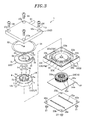
- Fig. 3 is an exploded perspective view showing the vane pump in accordance with the first embodiment of the present invention.
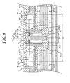
- Fig. 4 is a partially enlarged view of the vane pump shown in Fig. 2 .
- the upper side in Figs. 2 , 3 and 4 will be referred to as an axial upper side of a rotational axis Ax and the lower side as an axial lower side for the sake of convenience.
- a vane pump 1 for drawing and discharging a working fluid.
- the vane pump 1 in accordance with the present embodiment includes a casing 2, an annular ring 3 arranged within the casing 3 and provided with a substantially cylindrical inner circumferential surface 3a, and a rotary unit 4 rotating about a rotational axis Ax, the rotary unit 4 having a substantially cylindrical columnar base portion 5 with an outer circumferential surface 5a.
- An annular chamber 6 for containing a working fluid (liquid) is formed between the inner circumferential surface 3a of the annular ring 3 and the outer circumferential surface 5a of the base portion 5 of the rotary unit 4.
- the width w of the annular chamber 6 varies along the circumferential direction of the rotational axis Ax.
- the center C of the inner circumferential surface 3a is offset from the rotational axis Ax in parallel so that the base portion 5 of the rotary unit 4 is off-centered with respect to the inner circumferential surface 3a of the annular ring 3. Therefore, the width w of the annular chamber 6 is minimized in the right end position in Fig. 1 .
- the width w is gradually increased clockwise from the right end position and is maximized in the left end position. Then the width w is gradually reduced clockwise from the left end position toward the right end position and is minimized in the right end position.
- the base portion 5 has a plurality of (four, in the present embodiment) slits 7 radially extending with respect to the rotational axis Ax of the rotary unit 4 and opened radially outwards.
- a vane 8 of substantially square bar shape or substantially band plate shape is slidably fitted in each of the slits 7.
- the vane 8 is forced radially outwards in each of the slits 7 by the centrifugal force generated upon rotation of the rotary unit 4 and by the pressure of the working fluid introduced into the portion each of the slits 7 near the rotational axis Ax. This ensures that the vane 8 rotates together with the rotary unit 4 while making sliding contact with the inner circumferential surface 3a.
- the annular chamber 6 is divided into a plurality of (four, in the present embodiment) pump chambers 9 by the vanes 8 circumferentially arranged at a regular pitch, the number of the pump chambers 9 being the same as the number of the vanes 8.
- the volumes of the pump chambers 9 vary with the change in the width w of the annular chamber 6. In other words, the volume of each of the pump chambers 9 is minimized in the right end position in Fig. 1 .
- the rotary unit 4 rotates in the rotational direction RD (clockwise in Fig. 1 ), the volume of each of the pump chambers 9 is gradually increased and maximized in the left end position.
- the volume of each of the pump chambers 9 is gradually reduced and minimized in the right end position.
- the volume of each of the pump chambers 9 is expanded in the lower half section in Fig. 1 and contracted in the upper half section during one clockwise revolution of the rotary unit 4.
- an inlet port 11 is formed so as to face the volume expanding section and an outlet port 12 is formed so as to face the volume contracting section.
- the inlet port 11 communicates with an intake path 14 of an intake pipe 13 protruding from one side surface of the below-mentioned first casing body 10.
- the outlet port 12 remains in communication with a discharge path 16 defined within a discharge pipe 15 protruding parallel to the intake pipe 13.
- the pump chamber 9 defined by two adjoining vanes 8 moves from the right end position to the left end position while expanding the volume thereof.
- the working fluid is drawn from the intake path 14 into the pump chamber 9 through the inlet port 11.
- the pump chamber 9 moves from the left end position to the right end position while contracting the volume thereof.
- the working fluid is discharged from the pump chamber 9 toward the discharge path 16 through the outlet port 12.
- the drawing and discharging operations of the working fluid is performed one after another with respect to the plurality of pump chambers 9, whereby the working fluid is continuously drawn and discharged by the vane pump 1.
- the slits 7 formed in the base portion 5 of the rotary unit 4 are closed by a bottom wall portion 17 at the axial lower sides thereof.
- the vanes 8 are allowed to reciprocate within the slits 7 while making sliding contact with the bottom wall portion 17.
- the bottom wall portion 17 of the present embodiment is equivalent to a guide wall portion that radially guides the vanes 8 at the axial lower sides of the slits 7.
- the bottom wall portion 17 has communication holes 17a communicating with the radial inner portions of the slits 7. The pressure of the working fluid is introduced into the slits 7 from the rear surface side (the axial lower side) of the bottom wall portion 17 through the communication holes 17a.
- the bottom wall portion 17 is formed into a disk shape in a concentric but perpendicular relationship with the rotational axis Ax.
- the bottom wall portion 17 extends radially outwards beyond the outer circumferential surface 5a of the base portion 5 in a flange-like shape.
- a substantially cylindrical skirt portion 18 protrudes from the outer peripheral edge of the bottom wall portion 17.
- the skirt portion 18 is concentric with the rotational axis Ax and protrudes away from the base portion 5 (i.e., toward the axial lower side) with a substantially uniform thickness.
- the skirt portion 18 functions as a rotor of an electric motor 19 for driving the rotary unit 4 and includes a magnetization portion 18a alternately magnetized with N and S poles along the circumferential direction thereof in a corresponding relationship with the teeth 20a of a stator core 20 wound with coils. At least the portion of the skirt portion 18, which serves as the magnetization portion 18a, is made of a magnetic material. In this regard, only the portion of the skirt portion 18 facing the teeth 20a may be made of a magnetic material (e.g., a hard magnetic material such as a ferrite magnet or a samarium cobalt magnet). Alternatively, the entirety of the skirt portion 18 or the entirety of the rotary unit 4 may be made of a magnetic material. In this case, the rotary unit 4 or the skirt portion 18 can be molded by mixing a resin material with powdery or granular magnetic filler formed of a magnetic material.
- the outer circumferential surface 5a of the base portion 5 is regularly indented radially inwards at a specified pitch to thereby form blade portions 5b. These blade portions 5b rotate together with the base portion 5 (the rotary unit 4).
- the ability of the vane pump 1 to draw the working fluid into each of the pump chambers 9 is enhanced when the blade portions 5b oppose the inlet port 11, and the ability of the vane pump 1 to discharge the working fluid from the pump chambers 9 is improved when the blade portions 5b oppose the outlet port 12.
- a bearing 22 for rotatably supporting a shaft 21 is fixed in the central portion of the base portion 5 (the rotary unit 4).
- the bearing 22 may be a slide bearing such as a metal bush or the like or may be a rolling bearing such as a needle bearing or the like.
- the rotary unit 4 is configured to rotate about the rotational axis Ax within an internal space 2a (see Fig. 2 ) defined by the casing 2.
- the casing 2 includes a first casing body 10 arranged at the axial upper side (or at the upper side in Figs. 2 and 3 ) and a second casing body 23 positioned at the axial lower side (or at the lower side in Figs. 2 and 3 ).
- the ring 3 for defining the outer circumference of the annular chamber 6(the inner circumferential surface 3a) is arranged within the casing 2.
- the ring 3 includes a tubular portion 3b defining the outer circumference of the annular chamber 6, an annular flange portion 3c extending radially outwards from the axial lower side of the tubular portion 3b, and ribs 3d forming a portion of the side walls of the intake path 14 and the discharge path 16.
- the tubular portion 3b and the ribs 3d are upstanding from the flange portion 3c substantially at the same height in the axial direction of the rotational axis Ax.
- the ring 3 is accommodated within a recess portion 10b formed in the first casing body 10.
- the recess portion 10b is recessed in such a shape that the tubular portion 3b and the ribs 3d of the ring 3 can be fitted thereto.
- the flange portion 3c of the ring 3 has an outer peripheral portion 3e that makes contact with an annular wall portion 23a of the second casing body 23 at the opposite side from the recess portion 10b.
- the outer peripheral portion 3e is gripped by the first and second casing bodies 10 and 23 so that that the ring 3 can be fixed in the direction of the rotational axis Ax.
- the second casing body 23 includes a substantially annular recess portion 23b for accommodating the skirt portion 18 of the rotary unit 4 and a recess portion 23c for accommodating the portion of the bearing 22 of the rotary unit 4 that protrudes toward the second casing body 23 (i.e., toward the axial lower side or the lower side in Figs. 2 and 3 ).
- An annular groove portion 23d for holding an O-ring 34 is formed on the contact surface.
- the O-ring 34 fitted into the groove portion 23d provides a seal in the boundary portion between the first and second casing bodies 10 and 23.
- Seal members e.g., gaskets or O-rings
- the shaft 21 is installed to extend between the bottom wall portion 23e of the recess portion 23c and the protrusion portion 10c of the first casing body 10, the center of the shaft 21 being aligned with the rotational axis Ax.
- the shaft 21 extends through the bearing 22 provided at the center of the rotary unit 4 and is rotatably supported by the bearing 22.
- annular protrusion portion 23f protruding from the opposite side of the rotary unit 4 (i.e., the axial lower side or the lower side in Fig. 2 ) toward the rotary unit 4 is formed between the recess portion 23b and the recess portion 23c.
- a stator core 20 forming a part of the motor 19 is accommodated within an annular recess portion 23j defined on the rear surface of the protrusion portion 23f.
- the stator core 20 is attached to the central area of a surface 24a of a substrate 24.
- the stator core 20 includes a cylinder portion 20b centrally positioned in a concentric relationship with the rotational axis Ax and a plurality of teeth 20a extending radially outwards from the cylinder portion 20b. Coils are wound on the teeth 20a.
- Various kinds of electronic parts are mounted on the rear surface 24b of the substrate 24, i.e., on the opposite side (the axial lower side or the lower side in Fig. 2 ) of the substrate 24 from the surface 24a provided with the stator core 20.
- a circuit for driving the motor 19 and other circuits are also formed on the rear surface 24b of the substrate 24.
- the current supply state of the coils wound on the respective teeth 20a are suitably changed by a driving circuit formed in the substrate 24 to switch the polarities of the outer peripheral portions of the teeth 20a.
- a circumferential thrust force is applied to the magnetization portion 18a (the skirt portion 18) radially opposing the teeth 20a, thereby rotating the rotary unit 4.
- the partition wall portion 23g of the second casing body 23 interposed between the outer peripheral portions of the stator core 20 (the teeth 20a) and the skirt portion 18 needs to be made magnetically permeable.
- the partition wall portion 23g or the entirety of the second casing body 23 is made of a magnetically permeable material (e.g., stainless steel or resin).
- the substrate 24 is attached so as to close the recess portion 23j from the opposite side (the axial lower side) of the rotary unit 4. Furthermore, the substrate 24 is covered by a substrate cover 25 from the opposite side (the axial lower side) of the rotary unit 4.
- the substrate cover 25 is provided with lugs 25a that create a gap for arrangement of electronic parts between the substrate 24 and the substrate cover 25.
- the first and second casing bodies 10 and 23 have a substantially square shape when seen in the direction of the rotational axis Ax.
- the vane pump 1 is fabricated by inserting the screws 26 into the through-holes 10a and 23k and the through-holes 25b formed in the four corners of the substrate cover 25 and then threadedly coupling nuts 27 to the screws 26.
- the material and production method of the respective component parts of the vane pump 1 is suitably selected by taking into account the wear resistance, corrosion resistance, swelling resistance, moldability and part accuracy as well as the magnetizability and magnetic permeability mentioned above.
- the rotary unit 4 includes a hydraulic force generating portion 28 that generates, upon rotation of the rotary unit 4, a hydraulic force acting toward the axial upper side of the rotational axis Ax (i.e., toward the upper side in Figs. 2 and 3 ).
- the hydraulic force thus generated presses the rotary unit 4 against the first casing body 10 which is positioned at the opposite side from the bottom wall portion 17.
- the hydraulic force generating portion 28 includes slanting surfaces formed on the end surface 18b of the axial lower side of the skirt portion 18 and inclined with respect to the rotational direction RD of the rotary unit 4.
- the slanting surfaces are formed to obliquely extend from the axial lower side toward the axial upper side (i.e., from the lower side toward the upper side in Fig. 3 ) in between the leading end and the trailing end thereof along the rotational direction RD. Therefore, the working fluid impinging against the slanting surfaces during rotation of the rotary unit 4 applies a hydraulic force to the rotary unit 4, thereby pushing the rotary unit 4 toward the axial upper side (i.e., the upper side in Fig. 3 ).
- the first casing body 10 is provided with a thrust support portion 29 for slidably supporting the rotary unit 4 that rotates under the hydraulic force (or the thrust force) acting toward the axial upper side. More specifically, the portion of the first casing body 10 supporting the shaft 21 inserted therein protrudes toward the axial lower side to form a protrusion portion 10c with a tip end surface 10d.
- a recess portion 4a with a bottom surface 4b is formed in the central portion of the rotary unit 4 (the base portion 5). The bottom surface 4b of the recess portion 4a makes contact with the tip end surface 10d of the protrusion portion 10c through a washer 30.
- the washer 30 is interposed between the thrust support portion 29 and the base portion 5 of the rotary unit 4, and the axial end surface 22a of the bearing 22 arranged in the central portion of the rotary unit 4 (and partially exposed in the bottom surface 4b of the recess portion 4a) is allowed to make contact with the washer 30.
- This makes it easy to increase the wear resistance of the thrust support portion 29 and the base portion 5 of the rotary unit 4.
- the wear resistance of the thrust support portion 29 and the base portion 5 of the rotary unit 4 can be adjusted by changing the specifications (such as the material, size and hardening treatment) of the washer 30 and the sliding contact portion of the bearing 22.
- the specifications of the main body portion (including the base portion 5 and the bottom wall portion 17) of the rotary unit 4 can be set from the standpoint of weight reduction, slidability of other sliding portions, corrosion resistance and so forth.
- the diameter D2 of the sliding portion of the thrust support portion 29 is set smaller than the diameter D1 of the base portion 5. If no particular thrust support portion is employed despite the provision of the hydraulic force generating portion 28, the end surface 5c of the base portion 5 will make sliding contact with the first casing body 10, which may possibly lead to increased sliding resistance. Since the diameter D2 of the sliding portion of the thrust support portion 29 is set smaller than the diameter D1 of the base portion 5 in the present embodiment, it is possible to further reduce the sliding resistance and the friction of the rotary unit 4.
- the gap 31 between one axial end surface 17b of the bottom wall portion 17 and the other axial end surface 3f of the ring 3 is set narrow in order to reduce, as far as possible, the quantity of the working fluid leaked through the gap between the end surfaces 17b and 3f.
- a washer is also arranged in the axial lower side of the bearing 22.
- the gap between the outer circumferential surface 5a of the base portion 5 and the inner circumferential surface 3a of the ring 3 (or the outer circumferential surface of the annular chamber 6), i.e., the width w of the annular chamber 6, is smallest in the right end position Pd and greatest in the left end position Pp in Fig. 1 .
- the section extending from the right end position Pd to the left end position Pp along the rotational direction RD becomes an expanding section.
- the section extending from the left end position Pp to the right end position Pd along the rotational direction RD becomes a contracting section.
- the right end position Pd is the starting position of the expanding section and the terminating position of the contracting section
- the left end position Pp is the terminating position of the expanding section and the starting position of the contracting section.
- a middle position Pmi the exactly middle position between the starting position Pd and the terminating position Pp of the expanding section
- a middle position Pmo the exactly middle position between the starting position Pp and the terminating position Pd of the contracting section
- the inlet port 11 through which to draw the working fluid is arranged to face the portion of the annular chamber 6 extending between the middle position Pmi and the terminating position Pp of the expanding section in which the pump chamber 9 expands. More specifically, the trailing side edge 11a and the leading side edge 11b of the inlet port 11 along the rotational direction RD are all arranged within the angular range of 90 degrees extending from the middle position Pmi to the terminating position Pp. Needless to say, the trailing side edge 11a may be arranged in the middle position Pmi, the leading side edge 11b being in the terminating position Pp.
- the fluid moving from the intake path 14 toward the annular chamber 6 flows from the side (the lower side in Fig. 1 ) distant from an imaginary line segment interconnecting the starting position Pd and the terminating position Pp of the expanding section of the pump chamber 9 (a single-dotted chain line laterally extending through the rotational axis Ax in Fig. 1 ) toward the imaginary line segment (toward the upper side in Fig. 1 ).
- the fluid in the pump chamber 9 also flows toward the imaginary line segment. Therefore, the fluid introduced from the intake path 14 into the annular chamber 6 and the fluid moving together with the movement of the pump chamber 9 (the vanes 8) are prevented from colliding with each other in the vicinity of the inlet port 11. This makes it possible to suppress the reduction in pump efficiency attributable to the turbulence or vortex of the fluid which would otherwise be generated near the inlet port 11.
- the discharge path 16 includes a wall surface 12a positioned on the radially outer side with respect to the rotational axis Ax and joined to the outlet port 12 so as to extend along the tangential line of the outer circumferential surface of the annular chamber 6, i.e., the inner circumferential surface 3a of the ring 3.
- the inner circumferential surface 3a of the ring 3 can be smoothly joined to the wall surface 12a of the discharge path 16. This makes it possible to suppress the reduction in pump efficiency attributable to the separation or turbulence of the fluid which would otherwise be generated near the outlet port 12.
- the rotary unit 4 is pushed toward the axial upper side of the rotational axis Ax by the hydraulic force generating portion 28.
- the hydraulic force generating portion 28 it is possible to suppress the rotary unit 4 from making axial reciprocating movement during its rotation by pressing the rotary unit 4 against the axial upper side of the casing 2 (against the first casing body 10). This makes it possible to suppress generation of vibration or noises caused by the axial reciprocating movement.
- the gap g between the axial upper side end surface 5c of the base portion 5 and the axial lower side end surface 10e of the first casing body 10 can be defined with increased precision and accuracy by suitably setting the size d1 of the rotary unit 4 and the size d2 of the first casing body 10. This makes it possible to avoid the increase in leaked fluid quantity and the reduction in pump efficiency, which would be caused by the increase and change of the gap size. In addition, it is possible to reduce the variation (the pump-by-pump variation) in the discharge amount of the vane pump 1.
- Provision of the bottom wall portion 17 for slidably supporting the vanes 8 at the axial lower side thereof makes it possible to suppress the vanes 8 from moving toward the axial lower side. This helps prevent the generation of vibration or noises which would be caused by the axial reciprocating movement of the vanes 8, while suppressing the reduction in pump efficiency which would be caused by the increase in leaked fluid quantity. With this configuration, the rotary unit 4 and the vanes 8 are caused to move toward the axial upper side.
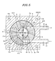
- Fig. 5 is a section view of a vane pump in accordance with a second embodiment of the present invention, which is taken along the plane perpendicular to the rotational axis of the vane pump.
- the vane pump of the present embodiment has essentially the same configuration as the vane pump 1 described in respect of the first embodiment.
- the inlet port 11 through which to draw the working fluid is arranged to face the portion of the annular chamber 6 extending between the middle position Pmi and the terminating position Pp of the expanding section in which the pump chamber 9 expands.
- the discharge path 16 includes a wall surface 12a positioned on the radially outer side with respect to the rotational axis Ax and joined to the outlet port 12 so as to extend along the tangential line of the outer circumferential surface of the annular chamber 6, i.e., the inner circumferential surface 3a of the ring 3.
- the intake path 14 arranged on the upstream side of the inlet port 11 includes a wall surface 11c positioned on the radially outer side with respect to the rotational axis Ax and joined to the inlet port 11 so as to extend along the tangential line of the outer circumferential surface of the annular chamber 6, i.e., the inner circumferential surface 3a of the ring 3.
- the wall surface 11c of the intake path 14 can be smoothly joined to the inner circumferential surface 3a of the ring 3. This makes it possible to suppress the reduction in pump efficiency attributable to the separation or turbulence of the fluid which would otherwise be generated near the inlet port 11.
- the present invention is not limited to the embodiments and modified examples described above but may be changed or modified in many different forms.
- the detailed configuration of the rotary unit, the ring and the casing of the vane pump is not limited to the above-described embodiments.
- the position and shape of the inlet port, the outlet port, the intake path and the discharge path may be arbitrarily changed or combined within the scope of the present invention.
Landscapes
- Engineering & Computer Science (AREA)
- Mechanical Engineering (AREA)
- General Engineering & Computer Science (AREA)
- Rotary Pumps (AREA)
- Details And Applications Of Rotary Liquid Pumps (AREA)
- Structures Of Non-Positive Displacement Pumps (AREA)
Applications Claiming Priority (1)
| Application Number | Priority Date | Filing Date | Title |
|---|---|---|---|
| JP2008187209A JP4780154B2 (ja) | 2008-07-18 | 2008-07-18 | ベーンポンプ |
Publications (2)
| Publication Number | Publication Date |
|---|---|
| EP2146096A2 true EP2146096A2 (fr) | 2010-01-20 |
| EP2146096A3 EP2146096A3 (fr) | 2015-01-14 |
Family
ID=40902891
Family Applications (1)
| Application Number | Title | Priority Date | Filing Date |
|---|---|---|---|
| EP09009171.1A Withdrawn EP2146096A3 (fr) | 2008-07-18 | 2009-07-14 | Pompe à palettes |
Country Status (6)
| Country | Link |
|---|---|
| US (1) | US8257071B2 (fr) |
| EP (1) | EP2146096A3 (fr) |
| JP (1) | JP4780154B2 (fr) |
| KR (1) | KR101121304B1 (fr) |
| CN (1) | CN101629568A (fr) |
| TW (1) | TWI390110B (fr) |
Families Citing this family (5)
| Publication number | Priority date | Publication date | Assignee | Title |
|---|---|---|---|---|
| JP5643923B2 (ja) | 2011-12-21 | 2014-12-24 | 株式会社リッチストーン | ロータリカムリング流体機械 |
| EP3056737B1 (fr) * | 2015-02-11 | 2017-11-15 | Danfoss A/S | Pompe à ailettes |
| DE102016113745A1 (de) * | 2016-07-26 | 2018-02-01 | HELLA GmbH & Co. KGaA | Flügelzellenpumpe, insbesondere Vakuumpumpe |
| TWI614408B (zh) * | 2017-03-09 | 2018-02-11 | 液壓葉片泵之泵芯結構 | |
| US11990819B2 (en) | 2020-11-24 | 2024-05-21 | Bosch Rexroth Corporation | Electric and hydraulic machine |
Citations (1)
| Publication number | Priority date | Publication date | Assignee | Title |
|---|---|---|---|---|
| JPH0942187A (ja) | 1995-07-28 | 1997-02-10 | Tohatsu Corp | 給水ポンプの呼び水装置 |
Family Cites Families (14)
| Publication number | Priority date | Publication date | Assignee | Title |
|---|---|---|---|---|
| DE457091C (de) * | 1928-03-08 | Harry Sauveur Dipl Ing | Laufbuchse fuer Vielzellenpumpen | |
| US1455252A (en) * | 1921-07-15 | 1923-05-15 | Nat Pump Company | Rotary pump |
| US1492456A (en) * | 1923-04-12 | 1924-04-29 | Hansen-Ellehammer Ja Christian | Rotary pump |
| US2536938A (en) * | 1941-07-05 | 1951-01-02 | George D Hunter | Rotary fluid motor |
| JPS52137705A (en) * | 1976-05-13 | 1977-11-17 | Misae Isaki | Vane pumps |
| JPS5543211A (en) * | 1978-09-20 | 1980-03-27 | Hokuetsu Kogyo Co Ltd | Compressor |
| US4561834A (en) * | 1983-07-13 | 1985-12-31 | Poss Design Limited | Rotary vaned pumps with fixed length and shearing knife-edged vanes |
| JPS6328892U (fr) * | 1986-08-12 | 1988-02-25 | ||
| JPH01267385A (ja) * | 1988-04-15 | 1989-10-25 | Nippon Piston Ring Co Ltd | ベーン型真空ポンプ |
| JPH081180B2 (ja) | 1992-07-20 | 1996-01-10 | 財団法人電力中央研究所 | ベーンロータリーコンプレッサー |
| DE9211768U1 (de) * | 1992-09-02 | 1992-11-12 | Lorentz, Bernt, 2000 Hamburg | Flügelzellenmaschine |
| JP2008151113A (ja) * | 2006-11-20 | 2008-07-03 | Matsushita Electric Works Ltd | ベーンポンプ |
| JP2008128201A (ja) * | 2006-11-24 | 2008-06-05 | Matsushita Electric Works Ltd | ベーンポンプ |
| EP2075469A2 (fr) * | 2007-12-25 | 2009-07-01 | Panasonic Electric Works Co., Ltd. | Pompe à palettes |
-
2008
- 2008-07-18 JP JP2008187209A patent/JP4780154B2/ja active Active
-
2009
- 2009-07-10 KR KR1020090063053A patent/KR101121304B1/ko not_active Expired - Fee Related
- 2009-07-14 US US12/458,469 patent/US8257071B2/en not_active Expired - Fee Related
- 2009-07-14 EP EP09009171.1A patent/EP2146096A3/fr not_active Withdrawn
- 2009-07-15 TW TW098123896A patent/TWI390110B/zh not_active IP Right Cessation
- 2009-07-17 CN CN200910160725A patent/CN101629568A/zh active Pending
Patent Citations (1)
| Publication number | Priority date | Publication date | Assignee | Title |
|---|---|---|---|---|
| JPH0942187A (ja) | 1995-07-28 | 1997-02-10 | Tohatsu Corp | 給水ポンプの呼び水装置 |
Also Published As
| Publication number | Publication date |
|---|---|
| CN101629568A (zh) | 2010-01-20 |
| JP2010024958A (ja) | 2010-02-04 |
| US20100015001A1 (en) | 2010-01-21 |
| TWI390110B (zh) | 2013-03-21 |
| EP2146096A3 (fr) | 2015-01-14 |
| TW201009195A (en) | 2010-03-01 |
| US8257071B2 (en) | 2012-09-04 |
| KR20100009484A (ko) | 2010-01-27 |
| KR101121304B1 (ko) | 2012-03-23 |
| JP4780154B2 (ja) | 2011-09-28 |
Similar Documents
| Publication | Publication Date | Title |
|---|---|---|
| US8257071B2 (en) | Vane pump | |
| JP4811496B2 (ja) | 燃料ポンプ | |
| KR20090069244A (ko) | 베인 펌프 | |
| JP2011241687A (ja) | ベーンポンプ | |
| JP4636108B2 (ja) | ベーンポンプ | |
| JP5033614B2 (ja) | ベーンポンプ | |
| JP5097041B2 (ja) | ベーンポンプ | |
| JP5117949B2 (ja) | ベーンポンプ | |
| JP5060999B2 (ja) | ベーンポンプ | |
| JP4300529B2 (ja) | ベーン式ポンプ | |
| WO2010007864A1 (fr) | Pompe à palettes | |
| JP2012047074A (ja) | ベーンポンプ | |
| JP5150240B2 (ja) | ベーンポンプ | |
| JP2009228455A (ja) | ベーンポンプ | |
| JP2010024944A (ja) | ベーンポンプ | |
| US10233881B2 (en) | Fuel pump | |
| JP2009228458A (ja) | ベーンポンプ | |
| JP2009228454A (ja) | ベーンポンプ | |
| JP2010024947A (ja) | ベーンポンプ | |
| JP2009228451A (ja) | ベーンポンプ | |
| JP2009156053A (ja) | ベーンポンプ | |
| JP2009228452A (ja) | ベーンポンプ | |
| JP2010024954A (ja) | ベーンポンプ | |
| JP2009156050A (ja) | ベーンポンプ | |
| JP2009156083A (ja) | ベーンポンプ |
Legal Events
| Date | Code | Title | Description |
|---|---|---|---|
| PUAI | Public reference made under article 153(3) epc to a published international application that has entered the european phase |
Free format text: ORIGINAL CODE: 0009012 |
|
| AK | Designated contracting states |
Kind code of ref document: A2 Designated state(s): AT BE BG CH CY CZ DE DK EE ES FI FR GB GR HR HU IE IS IT LI LT LU LV MC MK MT NL NO PL PT RO SE SI SK SM TR |
|
| AX | Request for extension of the european patent |
Extension state: AL BA RS |
|
| RAP1 | Party data changed (applicant data changed or rights of an application transferred) |
Owner name: PANASONIC CORPORATION |
|
| PUAL | Search report despatched |
Free format text: ORIGINAL CODE: 0009013 |
|
| AK | Designated contracting states |
Kind code of ref document: A3 Designated state(s): AT BE BG CH CY CZ DE DK EE ES FI FR GB GR HR HU IE IS IT LI LT LU LV MC MK MT NL NO PL PT RO SE SI SK SM TR |
|
| AX | Request for extension of the european patent |
Extension state: AL BA RS |
|
| RIC1 | Information provided on ipc code assigned before grant |
Ipc: F04C 2/344 20060101AFI20141205BHEP |
|
| STAA | Information on the status of an ep patent application or granted ep patent |
Free format text: STATUS: THE APPLICATION IS DEEMED TO BE WITHDRAWN |
|
| 18D | Application deemed to be withdrawn |
Effective date: 20150715 |