EP2146101A2 - Elément de liaison - Google Patents
Elément de liaison Download PDFInfo
- Publication number
- EP2146101A2 EP2146101A2 EP20080017422 EP08017422A EP2146101A2 EP 2146101 A2 EP2146101 A2 EP 2146101A2 EP 20080017422 EP20080017422 EP 20080017422 EP 08017422 A EP08017422 A EP 08017422A EP 2146101 A2 EP2146101 A2 EP 2146101A2
- Authority
- EP
- European Patent Office
- Prior art keywords
- section
- connecting element
- clamping
- element according
- base body
- Prior art date
- Legal status (The legal status is an assumption and is not a legal conclusion. Google has not performed a legal analysis and makes no representation as to the accuracy of the status listed.)
- Withdrawn
Links
- 230000005540 biological transmission Effects 0.000 claims description 12
- 239000013013 elastic material Substances 0.000 claims description 5
- 238000003780 insertion Methods 0.000 claims description 3
- 230000037431 insertion Effects 0.000 claims description 3
- 238000012546 transfer Methods 0.000 claims description 3
- HCHKCACWOHOZIP-UHFFFAOYSA-N Zinc Chemical compound [Zn] HCHKCACWOHOZIP-UHFFFAOYSA-N 0.000 claims description 2
- 239000011152 fibreglass Substances 0.000 claims description 2
- 239000002184 metal Substances 0.000 claims description 2
- 229910052751 metal Inorganic materials 0.000 claims description 2
- 229910001220 stainless steel Inorganic materials 0.000 claims description 2
- 239000010935 stainless steel Substances 0.000 claims description 2
- 239000011701 zinc Substances 0.000 claims description 2
- 229910052725 zinc Inorganic materials 0.000 claims description 2
- 238000013461 design Methods 0.000 description 9
- 230000008878 coupling Effects 0.000 description 7
- 238000010168 coupling process Methods 0.000 description 7
- 238000005859 coupling reaction Methods 0.000 description 7
- 238000005452 bending Methods 0.000 description 3
- 230000000694 effects Effects 0.000 description 3
- 239000006260 foam Substances 0.000 description 3
- 230000015572 biosynthetic process Effects 0.000 description 2
- 150000001875 compounds Chemical class 0.000 description 2
- 238000006073 displacement reaction Methods 0.000 description 2
- 230000002349 favourable effect Effects 0.000 description 2
- 238000004519 manufacturing process Methods 0.000 description 2
- 238000000926 separation method Methods 0.000 description 2
- 238000013459 approach Methods 0.000 description 1
- 230000001419 dependent effect Effects 0.000 description 1
- 238000011161 development Methods 0.000 description 1
- 230000018109 developmental process Effects 0.000 description 1
- 238000000605 extraction Methods 0.000 description 1
- -1 for example Substances 0.000 description 1
- 230000005283 ground state Effects 0.000 description 1
- 230000003993 interaction Effects 0.000 description 1
- 230000001404 mediated effect Effects 0.000 description 1
- 230000002093 peripheral effect Effects 0.000 description 1
- 239000003566 sealing material Substances 0.000 description 1
Images



Classifications
-
- F—MECHANICAL ENGINEERING; LIGHTING; HEATING; WEAPONS; BLASTING
- F16—ENGINEERING ELEMENTS AND UNITS; GENERAL MEASURES FOR PRODUCING AND MAINTAINING EFFECTIVE FUNCTIONING OF MACHINES OR INSTALLATIONS; THERMAL INSULATION IN GENERAL
- F16B—DEVICES FOR FASTENING OR SECURING CONSTRUCTIONAL ELEMENTS OR MACHINE PARTS TOGETHER, e.g. NAILS, BOLTS, CIRCLIPS, CLAMPS, CLIPS OR WEDGES; JOINTS OR JOINTING
- F16B7/00—Connections of rods or tubes, e.g. of non-circular section, mutually, including resilient connections
- F16B7/04—Clamping or clipping connections
- F16B7/044—Clamping or clipping connections for rods or tubes being in angled relationship
- F16B7/0446—Clamping or clipping connections for rods or tubes being in angled relationship for tubes using the innerside thereof
- F16B7/0453—Clamping or clipping connections for rods or tubes being in angled relationship for tubes using the innerside thereof the tubes being drawn towards each other
- F16B7/0466—Clamping or clipping connections for rods or tubes being in angled relationship for tubes using the innerside thereof the tubes being drawn towards each other by a screw-threaded stud with a conical tip acting on an inclined surface
Definitions
- the present invention relates to a connecting element for connecting a pipe section with at least one further element, in particular for the end-side connecting two handrail sections, with an insertable into the pipe section body and at least one adjusting element, through which the body between a mounting state, which insertion and extraction of the body with respect to the tube section, and an expanded connection state in which the inserted portion of the body is held out of the tube in a secure manner, is adjustable.
- Such a connecting element may be, for example, a component of a handrail system in which a number of tubular gripping elements are connected together to obtain a handrail bar of a desired overall length. Due to the fact that, when two pipe sections are coupled, the base body is inserted into the pipe sections and clamped in the pipe sections, the connecting element is essentially completely concealed inside the pipe sections, whereby a visually appealing design of the handrail system is possible.
- a handrail system and connecting elements may be provided which do not serve to couple two pipe sections, but for coupling a pipe section with a separate functional element. For example, a corner or a final ornamental element may be formed directly on an end portion of the connecting element.
- the base body has at least one first and one second clamping section, which are movable relative to one another, wherein the adjusting element is movably mounted in the first clamping section along a predetermined adjustment axis and has an active surface which can be brought into engagement with an engagement surface associated with the second clamping section to expand the cross section of the body both in the direction of the adjustment axis and across it.
- the holding clamping force is distributed in a favorable manner on the inner peripheral surface of the pipe section.
- two pipe sections to be connected are automatically centered by the expansion of the connecting element in several directions on a common longitudinal axis, so that a possible step on the abutting edge relatively evenly over the entire circumference of the pipe section ends is distributed.
- a uniformly distributed over the circumference stage - from then correspondingly lesser height - is much less disturbing than, for example, a localized level stronger form.
- the widening of the body in several directions upon displacement of the adjusting in only a single direction can be achieved in an advantageous manner by a special design of the active surface of the adjustment and cooperating with this, the second clamping portion associated attack surface.
- the active surface of the adjusting element or the second clamping portion associated with the attack surface may for example be curved or inclined with respect to the adjustment. It is also possible for both surfaces to be correspondingly arched or inclined relative to the adjustment axis.
- Various combinations of surface curvatures and surface slopes are conceivable in order to achieve a distribution of compressive force in several directions. Examples relating to this are mentioned in the description of the figures.
- the second clamping portion comprises at least two separate subsections with these correspondingly associated engagement surfaces, wherein the subsections are movable transversely to the adjustment axis relative to each other, to ensure easy expandability of the body in the transverse direction.
- the separate subsections may, for example, be separated from one another by a longitudinal slot which passes through the second clamping section passes through. The entire length of the body can thus be used for a transversely directed to the adjustment clamping action.
- the adjustment member may be a grub screw having a conically shaped end surface received in a continuous threaded hole of the first clamping portion.
- a grub screw is simple and inexpensive to produce and allows through the conical end surface shape a desired force deflection away from the adjustment.
- the cross-sectional shape of the engagement surface assigned to the second clamping section corresponds at least in sections to the cross-sectional shape of the conically shaped end face of the grub screw.
- the second clamping portion may for example have obliquely to the adjustment axis extending surface portions, which correspond in their degree of inclination to the cone of the end surface of the grub screw, so that forms a substantially linear power transmission area between grub screw and second clamping body.
- the cone in particular allows a force transmission in two directions pointing away from each other transversely to the adjustment axis.
- an additional force transmission element or an arrangement of a plurality of force transmission elements can also be inserted between the grub screw and the second clamping section.
- the base body comprises a further adjusting element, wherein each of the two adjusting elements is assigned to one of two pipe sections to be connected.
- the first and the second clamping portion are elastically coupled together. This is advantageous because the first and the second clamping section automatically approach each other again when the adjusting element is reset and the cross-section of the basic body is thus reduced again.
- the connection of the two pipe sections can therefore be easily solved again, for example, to dismantle the handrail or when replacing a single handrail element.
- the number of items required for the fastener is reduced to a minimum, which simplifies the handling by a fitter.
- the main body has a substantially rectangular cross-section.
- the main body may be formed for example as a square tube and thus serve for connecting also formed as a square tubes handrail elements.
- a square tube is easy to manufacture and can be easily adapted to the circumference of the pipe sections of the associated handrail system.
- the first and the second clamping section can be separated from one another on each side by two blind slots extending through the main body at the end face, which are offset in the direction of the adjustment axis and overlap in a predetermined central region of the base body.
- blind slots can be created on each side of the body a substantially S-shaped connecting strut between the first and the second clamping portion.
- the active surface of the adjusting element does not have to be in direct contact with the second clamping section. It can e.g. be expedient for certain configurations, between the active surface of the adjusting element and the second clamping portion to arrange at least two transmission pieces, which transmit a force exerted by the active surface of the adjusting pressure force on the second clamping portion.
- the transmission pieces may have a deviating from the rectangular shape cross-section.
- they may be cylindrical bars or bars of triangular cross-section, thus providing the domed or inclined engagement surface. This may be particularly advantageous because it may be easier to produce a separate part with an inclined or curved surface than to make the main body itself with such an area.
- the base body is formed as a slotted block. This ensures, on the one hand, easy and cost-effective manufacturability and, on the other hand, high connection stability.
- the base body made of an elastic material, for example, zinc die-cast, stainless steel or glass fiber reinforced plastic.
- the elastic design of the entire body supports the distribution of the clamping force in as many directions as possible and also contributes to the solubility of the compound.
- the base body has at least two and in particular four protruding outwardly projecting portions.
- the protruding sections can be supported, for example, in the corner regions of a handrail element designed as a square tube and cause a diagonal force directed against the corner region in each case when the adjustment element is pressed onto a section of the base body located between the protrusion sections.
- the projection sections may be formed, for example, as spreader vanes, which extend away from a substantially perpendicular to the adjustment axis aligned central portion of the first clamping portion and / or the second clamping portion and which are inclined with respect to the adjustment axis.
- the first and the second clamping portion each have two spreader wings, which are aligned with each other at an angle of about 90 ° and which are inclined at an angle of about 45 ° with respect to the adjustment axis.
- the first clamping portion and the second clamping portion are formed as substantially U-shaped profile elements, which obliquely away from each other facing leg portions exhibit.
- the connecting element is in this case particularly inexpensive to produce, since the U-shaped profile elements can be manufactured as a simple stamped / bent parts.
- the adjusting element may be formed according to an embodiment of the invention as a grub screw, which has a threaded portion and a cylindrical guide portion, wherein between the threaded portion and the cylindrical guide portion forming an effective surface shoulder shoulder is formed.
- the grub screw can be screwed into a formed in the first clamping portion through threaded hole.
- the guide section may extend through a through hole formed in the second clamping section and be guided therein.
- Such a guide of the grub screw increases the overall stability of the connecting element and prevents unwanted slippage or distortion of the two clamping sections against each other.
- the neck shoulder imparts the adjustment force from the grub screw to the second pinch section, with an intermediate transfer piece, such as e.g. a washer, can be provided.
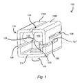
- the connecting element comprises a main body 100, which is designed here as a square tube with two end faces and a total of four side surfaces.
- the main body 100 can be a cast part or a stamped and bent part.
- the main body 100 is divided into a first clamping portion 116 and a second clamping portion 118, wherein the second clamping portion 118 has two separate subsections 118A, 118B.
- the first clamping portion 116 has a substantially U-shaped cross section, while the two subsections 118A, 118B of the second clamping portion 118 have a substantially L-shaped profile.
- a longitudinal slot 124 which extends through the entire second clamping section 118 at the upper side of the main body 100, effects the separation of the two subsections 118A, 118B of the second clamping section 118.
- the first clamping section 116 and the second clamping portion 118 are not completely separated from each other, but they are coupled to each other on two opposite sides of the base body 100 by a connecting strut 127 to each other.
- the connecting struts 127 are formed by S-shaped spars, which are each formed by two frontally extending through the base 100 therethrough, relatively offset blind slots 126, 128 are provided.
- the first clamping section 116 has on the underside two continuous threaded holes, in each of which a set as a grub screw with a conically shaped end surface adjusting element 114, 115 is added.
- the grub screws 114, 115 can with the help of a rotated from the outside tools in the threaded holes and so in the direction of an adjustment axis V ( Fig. 2 ) are adjusted.
- a transmission piece 130 is arranged, which in this embodiment is designed as a simple round bar.
- the diameter of the two round rods 130 is selected so that they touch centrally in a ground state of the connecting element and are supported by the end faces of the grub screws 114, 115.
- the adjustment axis V thus passes through the contact line of the round bars 130 and the longitudinal slot 124 therethrough.
- the end surfaces of the grub screws 114, 115 thus each form an effective surface 120, which is equally engaged with two round bars 130. More specifically, the active surface 120 is respectively in contact with an engagement surface 122 formed by a surface portion of the round bars 130.
- the second clamping portion 118 need not necessarily be divided by the longitudinal slot 124 into the subsections 118A, 118B. In the case of an integrally formed second clamping section 118, the force component directed transversely to the adjustment axis V would nevertheless bring about a certain bulging of the two side surfaces of the second clamping section 118 facing the first clamping section 116, which would likewise cause a widening of the cross section of the main body 100 transversely to the adjustment axis V.
- a connecting element according to the embodiment described above is based on Fig. 4 described, which shows a main body 100, which is partially inserted into an here formed angled pipe section 400 of a handrail system.
- the outer dimensions of the main body 100 are matched to the inner diameter of the pipe section 400 such that the connecting element with dissolved or missing grub screws 114, 115 easily in the pipe section 400 inserted, but is guided in this.
- the base body 100 is thus in an assembled state, which makes it possible to insert and extract the main body 100 with respect to the tube section 400.
- Through holes 410 are provided on the underside of the tube section 400 to allow actuation of the grub screws 114, 115. Screwing the grub screw 115 into the main body 100 by a predetermined amount transfers the main body 100 of the mounting state in an expanded connection state in which the inserted portion of the body is held by clamping forces pull-out safe in the pipe section.
- the compound can be solved at any time by the grub screws 114, 115 are unscrewed, which reduces due to the elastic design of the base body 100 and in particular the elastic coupling of first and second clamping portion 116, 118 of the cross section and the deadlock is released.
- any number of pipe sections 400 can be releasably connected to one another in this way.
- one of the grub screws 114, 115 is assigned to a pipe section 400 to be connected, which is why each pipe section 400 to be connected has a through hole 410 provided for the operation of the grub screws 114, 115.
- the base body 200 is not formed here as a square tube, but as a slotted square block of an elastic material. Similar to the first embodiment, the main body 200 is divided into a first clamping portion 216 and a second clamping portion 218 having two subsections 218A, 218B. Again, there are provided two grub screws 214, 215 with conically shaped end surfaces, each provided in a continuous threaded hole of the first clamping portion 216.
- a longitudinal slot 224 extends through the entire base body 200, the adjustment axis V passing through the longitudinal slot 224.
- blind slots 226, 228, are offset in the direction of the adjustment axis V against each other and overlap in a predetermined central region of the body 200.
- S-shaped connecting struts 227 are also provided here, which ensure a continuous but elastic coupling of the first clamping section 216 to the second clamping section 218. Due to the separation of the subsections 218A, 218B by the longitudinal slot 224, they are movable transversely to the adjustment axis V relative to each other, but only to a limited extent, as they are coupled by the connecting struts 227 to the one-piece first clamping portion 216.
- the sub-sections 218A, 218B each have a relative to the adjustment axis V inclined engagement surface 222, which is adapted to the active surface 220 of the grub screws 214, 215.
- a force is transmitted from the active surface 220 to the two inclined engagement surfaces 222.
- the force transmission by means of the corresponding oblique surfaces in turn leads to an additional force component directed transversely to the adjustment axis V and thus to a uniform force Expansion of the base body 200 in several directions.
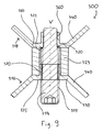
- the main body 300 here comprises a first clamping section 316 and a second clamping section 318, which are each formed as a substantially U-shaped profile element of elastic material with obliquely projecting legs.
- the profile elements 316, 318 are metal strips, which are arranged opposite one another and connected to each other by a coupling piece 323.
- Each of the profile elements 316, 318 has two longitudinally parallel bending edges 330. By the bending edges 330, the profile elements 316, 318 each in a direction perpendicular to the adjustment axis V (see Fig. 9 ) divided central portion 335 and two with respect to the adjustment axis V oppositely outwardly inclined projection portions 340.
- the protruding portions 340 are each at an angle of about 45 ° with respect to the adjustment axis to the outside and form a total of four Sp Rudigel that give the base 300 an X-shaped cross-section.
- the coupling piece 323 is a block of elastic material, for example a foam block, which is adhesively bonded to the first profile element 316 and the second profile element 318 in the area of the central portion 335.
- the two profile elements 316, 318 are always held together elastically so as to form the main body 300.
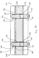
- two grub screws are provided in the connecting element according to the third embodiment, each having a threaded portion 355 and a cylindrical guide portion 360.
- the guide section 360 is tapered relative to the threaded section 355, so that a shoulder shoulder 365 (FIG. Fig. 10 ), which forms an active surface 320.
- a shoulder shoulder 365 FIG. Fig. 10
- the threaded holes 370 are opposed through holes 372 formed to receive the guide portions 360 of the grub screws 314, 315.
- the threaded holes 370 and the through holes 372 are formed in the foam block 323 channels to allow the passage of the grub screws 314, 315.
- the threaded holes 370 and the through-holes 372 are made with a flow drill to provide an annular ejection on the outside of the threaded holes 370 and the through-holes 372, respectively forming an axially elongated thread having a plurality of threads and an enlarged receiving portion 374 for the guide portion 360 is used.
- the two grub screws 314, 315 are threaded into the threaded holes 370 in the first profile member 316.
- the guide portion 360 engages with the receiving portion 374 and slides in this until the shoulder shoulder 365 abuts against the edge of the through hole 372.
- the region in which the shoulder shoulder 365 abuts against the second profile element 318 thus forms the engagement surface 322 (see FIG Fig. 9 ).
- Further screwing the grub screws 314, 315 then causes a compressive force on the central portion 335 of the second profile element 318.
- cover caps may be provided of sealing material, which at the corner regions have longitudinal slots and therefore can be plugged onto a protruding from the pipe section 400 portion of the base body 300, that the clamping surfaces of the spreader vanes 340 are exposed.
- Such caps can be used to seal the interior of the pipe section 400, if the associated handrail system is to be used for example in the sanitary area.
- an associated through hole 410 is provided on the corresponding pipe section 400.
- the main body 100, 200, 300 could also be inserted into the angled pipe section 400 such that one of the grub screws 114, 115, 214, 215, 314, 315 can be actuated through the frontal opening 420 of a leg of the angled pipe section 400, so for the corresponding grub screw no through hole 410 is provided. In this way, a more visually appealing design of the pipe section 400 can be achieved.
- the connecting element according to the invention come especially to advantage in a handrail system composed of square tubes.
- the base body 100, 200, 300 can also be subdivided into more than two clamping sections, and the engagement surfaces 120, 220, 320 of the second clamping section 118, 218, 318 can have more complex shapes.
- the only important aspect is the design of the force transmission surfaces on the adjusting elements and clamping sections in such a way that a transverse component is impressed on the displacement movement of the second clamping section 118, 218, 318 and thus a widening of the basic body 100, 200, 300 pointing in several directions is brought about.
Landscapes
- Engineering & Computer Science (AREA)
- General Engineering & Computer Science (AREA)
- Mechanical Engineering (AREA)
- Mutual Connection Of Rods And Tubes (AREA)
Priority Applications (1)
| Application Number | Priority Date | Filing Date | Title |
|---|---|---|---|
| EP20080017422 EP2146101A2 (fr) | 2008-07-17 | 2008-10-02 | Elément de liaison |
Applications Claiming Priority (2)
| Application Number | Priority Date | Filing Date | Title |
|---|---|---|---|
| EP08012930 | 2008-07-17 | ||
| EP20080017422 EP2146101A2 (fr) | 2008-07-17 | 2008-10-02 | Elément de liaison |
Publications (1)
| Publication Number | Publication Date |
|---|---|
| EP2146101A2 true EP2146101A2 (fr) | 2010-01-20 |
Family
ID=40220076
Family Applications (1)
| Application Number | Title | Priority Date | Filing Date |
|---|---|---|---|
| EP20080017422 Withdrawn EP2146101A2 (fr) | 2008-07-17 | 2008-10-02 | Elément de liaison |
Country Status (1)
| Country | Link |
|---|---|
| EP (1) | EP2146101A2 (fr) |
Cited By (4)
| Publication number | Priority date | Publication date | Assignee | Title |
|---|---|---|---|---|
| EP3406916A1 (fr) * | 2017-05-26 | 2018-11-28 | Syma Intercontinental AG | Équerre pour profilés de support |
| CN109764035A (zh) * | 2019-01-30 | 2019-05-17 | 长沙朗乐科技有限公司 | 一种内撑式管连接装置 |
| NL2033765B1 (en) * | 2022-12-20 | 2024-06-26 | D I S Holding B V | Combination for connecting rectangular profiles |
| WO2024133235A1 (fr) * | 2022-12-20 | 2024-06-27 | D.I.S. Holding B.V. | Combinaison pour relier des profils rectangulaires |
-
2008
- 2008-10-02 EP EP20080017422 patent/EP2146101A2/fr not_active Withdrawn
Cited By (4)
| Publication number | Priority date | Publication date | Assignee | Title |
|---|---|---|---|---|
| EP3406916A1 (fr) * | 2017-05-26 | 2018-11-28 | Syma Intercontinental AG | Équerre pour profilés de support |
| CN109764035A (zh) * | 2019-01-30 | 2019-05-17 | 长沙朗乐科技有限公司 | 一种内撑式管连接装置 |
| NL2033765B1 (en) * | 2022-12-20 | 2024-06-26 | D I S Holding B V | Combination for connecting rectangular profiles |
| WO2024133235A1 (fr) * | 2022-12-20 | 2024-06-27 | D.I.S. Holding B.V. | Combinaison pour relier des profils rectangulaires |
Similar Documents
| Publication | Publication Date | Title |
|---|---|---|
| DE69919724T2 (de) | Kupplungsvorrichtung | |
| EP1958825B1 (fr) | Dispositif de fixation | |
| DE102014110638A1 (de) | Schnell montierbare und demontierbare Schraubmuffe | |
| EP2150743B1 (fr) | Element raccord de serrage pour un tuyau | |
| DE19654435C2 (de) | Anordnung zur steckbaren Verbindung von Rohren oder Schläuchen mit Armaturen oder Fittings | |
| EP3027826B1 (fr) | Tube d'échafaudage et élément d'echafaudage | |
| EP1893903B1 (fr) | Emmanchement de compression conçu pour un tuyau | |
| EP3639334B1 (fr) | Fixation a un rail de support | |
| EP2433119A1 (fr) | Unité d'enfichage et système de liaison permettant la liaison de capillaires, notamment en chromatographie en phase liquide à hautes performances | |
| DE102011106696A1 (de) | Schraubelement zum Befestigen einer Leitung an einem Gegenstück | |
| EP0206327B1 (fr) | Dispositif de connexion d'éléments tubulaires | |
| WO2006048073A1 (fr) | Dispositif de raccordement servant a relier des conduites, et vehicule automobile equipe de ce dispositif de raccordement | |
| EP2146101A2 (fr) | Elément de liaison | |
| AT517612B1 (de) | Möbelbeschlag | |
| EP3529868B1 (fr) | Ensemble connecteur pour la connexion de deux châssis d'armoires électriques | |
| EP1615528A1 (fr) | Element de liaison et systeme de bati | |
| DE202007007827U1 (de) | Klemmfitting für ein Rohr | |
| DE102013208494A1 (de) | Vorrichtung zur werkzeuglosen Verbindung zweier Bauteile | |
| EP3586017B1 (fr) | Dispositif de fixation et module de fixation | |
| EP1219761B1 (fr) | Echafaudage avec un tube d'échafaudage | |
| DE102019130855A1 (de) | Verbindungssystem und Regalsystem | |
| EP1978195A1 (fr) | Armature enfichable | |
| DE20013949U1 (de) | Klemmstück | |
| DE602004002170T2 (de) | Abgedichtete Kupplungsvorrichtung für ein Rohr mit einem mit einem Gewinde versehenen Fortsatz | |
| DE19745494A1 (de) | Teleskopeinrichtung |
Legal Events
| Date | Code | Title | Description |
|---|---|---|---|
| PUAI | Public reference made under article 153(3) epc to a published international application that has entered the european phase |
Free format text: ORIGINAL CODE: 0009012 |
|
| AK | Designated contracting states |
Kind code of ref document: A2 Designated state(s): AT BE BG CH CY CZ DE DK EE ES FI FR GB GR HR HU IE IS IT LI LT LU LV MC MT NL NO PL PT RO SE SI SK TR |
|
| AX | Request for extension of the european patent |
Extension state: AL BA MK RS |
|
| STAA | Information on the status of an ep patent application or granted ep patent |
Free format text: STATUS: THE APPLICATION IS DEEMED TO BE WITHDRAWN |
|
| 18D | Application deemed to be withdrawn |
Effective date: 20110502 |