EP2146131A2 - Dispositif d'affichage - Google Patents
Dispositif d'affichage Download PDFInfo
- Publication number
- EP2146131A2 EP2146131A2 EP09009179A EP09009179A EP2146131A2 EP 2146131 A2 EP2146131 A2 EP 2146131A2 EP 09009179 A EP09009179 A EP 09009179A EP 09009179 A EP09009179 A EP 09009179A EP 2146131 A2 EP2146131 A2 EP 2146131A2
- Authority
- EP
- European Patent Office
- Prior art keywords
- main body
- display main
- friction member
- display
- display device
- Prior art date
- Legal status (The legal status is an assumption and is not a legal conclusion. Google has not performed a legal analysis and makes no representation as to the accuracy of the status listed.)
- Granted
Links
Images


Classifications
-
- H—ELECTRICITY
- H04—ELECTRIC COMMUNICATION TECHNIQUE
- H04N—PICTORIAL COMMUNICATION, e.g. TELEVISION
- H04N5/00—Details of television systems
- H04N5/64—Constructional details of receivers, e.g. cabinets or dust covers
- H04N5/655—Construction or mounting of chassis, e.g. for varying the elevation of the tube
-
- F—MECHANICAL ENGINEERING; LIGHTING; HEATING; WEAPONS; BLASTING
- F16—ENGINEERING ELEMENTS AND UNITS; GENERAL MEASURES FOR PRODUCING AND MAINTAINING EFFECTIVE FUNCTIONING OF MACHINES OR INSTALLATIONS; THERMAL INSULATION IN GENERAL
- F16M—FRAMES, CASINGS OR BEDS OF ENGINES, MACHINES OR APPARATUS, NOT SPECIFIC TO ENGINES, MACHINES OR APPARATUS PROVIDED FOR ELSEWHERE; STANDS; SUPPORTS
- F16M11/00—Stands or trestles as supports for apparatus or articles placed thereon ; Stands for scientific apparatus such as gravitational force meters
- F16M11/02—Heads
- F16M11/04—Means for attachment of apparatus; Means allowing adjustment of the apparatus relatively to the stand
- F16M11/06—Means for attachment of apparatus; Means allowing adjustment of the apparatus relatively to the stand allowing pivoting
- F16M11/10—Means for attachment of apparatus; Means allowing adjustment of the apparatus relatively to the stand allowing pivoting around a horizontal axis
-
- F—MECHANICAL ENGINEERING; LIGHTING; HEATING; WEAPONS; BLASTING
- F16—ENGINEERING ELEMENTS AND UNITS; GENERAL MEASURES FOR PRODUCING AND MAINTAINING EFFECTIVE FUNCTIONING OF MACHINES OR INSTALLATIONS; THERMAL INSULATION IN GENERAL
- F16M—FRAMES, CASINGS OR BEDS OF ENGINES, MACHINES OR APPARATUS, NOT SPECIFIC TO ENGINES, MACHINES OR APPARATUS PROVIDED FOR ELSEWHERE; STANDS; SUPPORTS
- F16M2200/00—Details of stands or supports
- F16M2200/08—Foot or support base
Definitions
- the present disclosure relates to a display device.
- a display device is configured to display images and includes a main body in which a display module is disposed.
- the main body may be supported by a stand unit or a wall. Recently, such a main body is tiltable by a stand unit. To make the main body tiltable, the stand unit is provided with a structure that is configured to support the weight of a display.
- Embodiments provide a display device that provides an additional frictional force according to a tilted angle while tilting the display device.
- a display device includes: a support part; a display main body tiltable relative to the support part; a first friction member generating a frictional force when tilting the display main body; and a second friction member generating a frictional force when the display main body is tilted at a predetermined angle or more.
- a display device in another embodiment, includes: a display main body tiltable back and forth; a stand body supporting the display main body; and a cover member that connects the stand body rotatably to the display main body, wherein the stand body includes: a first friction member that is brought in contact with a side of the display main body to generate a first frictional force when tilting the display main body; and a second friction member that is inserted into a guide hole provided to the display main body, and is, when tilting the display main body, selectively in contact with an inner surface of the guide hole to generate a second frictional force.
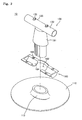
- Fig. 1 is a schematic view illustrating a display device according to an embodiment.
- Fig. 2 is an exploded perspective view illustrating a stand unit of Fig. 1 .
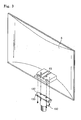
- Fig. 3 is a perspective view illustrating a rear cabinet to be coupled to the stand unit of Fig. 1 .
- Fig. 4 is a partial cut-away perspective view illustrating the rear cabinet coupled to the stand unit of Fig. 1 .
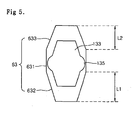
- Fig. 5 is a schematic view illustrating a relative position between a stopper and a guide hole when a display main body of Fig. 1 is not tilted.
- Figs. 6A and 6B are schematic views illustrating relative positions between the stopper and the guide hole when the display main body of Fig. 1 is tilted forward.
- Figs. 7A and 7B are schematic views illustrating relative positions between the stopper and the guide hole when the display main body of Fig. 1 is tilted rearward.
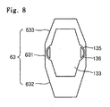
- Fig. 8 is a schematic view illustrating the stopper and the guide hole in the state where the display main body of Fig. 1 is not tilted, according to an embodiment.
- Fig. 1 is a schematic view illustrating a display device 1 according to an embodiment.
- the display device 1 includes a display main body 2 displaying an image, and a stand unit 10 that is coupled to the lower side of the display main body 2 to support the display main body 2.
- the display main body 2 includes a front cabinet 4 providing a front appearance, and a rear cabinet 6 of Fig. 3 coupled to the back of the front cabinet 4 to provide a rear appearance.
- a display module 5 is disposed between the front cabinet 4 and the rear cabinet 6.
- the display main body 2, supported by the stand unit 10, is rotatable (tiltable) back and forth.
- a frictional force between the display main body 2 and the stand unit 10 maintains a tilted position of the display main body 2.
- Fig. 2 is an exploded perspective view illustrating the stand unit 10.
- the stand unit 10 includes a base 110 disposed on a predetermined surface, a stand body 130 coupled to the base 110 to experience friction with the display main body 2 when tilting the display main body 2, and a cover member 160 coupled to the display main body 2 to support the stand body 130.
- a neck part 112 is disposed in the center of the base 110 to couple with the stand body 130.
- the stand body 130 includes a support part 131 coupled to the neck part 112, and a first friction member 132 formed in one piece with the upper side of the support part 131 to experience friction with the display main body 2 when tilting the display main body 2.
- the first friction member 132 is cylindrical and laterally elongated on the upper side of the support part 131. That is, the first friction member 132 extends horizontally.
- the first friction member 132 is placed on the lower side of the display main body 2 to produce friction between the display main body 2 and the outer surface of the first friction member 132 when tilting the display main body 2.
- the first friction member 132 functions as the rotation center of the display main body 2 and is cylindrical to rotate the display main body 2 about the first friction member 132.
- a plurality of stoppers 133 protrude from the upper side of the first friction member 132 to limit a tilting range of the display main body 2.
- a single stopper may be provided.
- the stoppers 133 are spaced apart from each other with respect to the center of the first friction member 132, and thus facilitating to limit the rotation of the display main body 2.
- the stoppers 133 are inserted into the display main body 2.
- Second friction members 135 are disposed on the lateral sides of each of the stoppers 133.
- the second friction members 135 are selectively in contact with guide holes 63 of Fig. 3 according to a rotation angle of the first friction member 132 relative to the display main body 2, so as to produce a second frictional force.
- first friction member 132 and the support part 131 are formed in one piece in the present embodiment, the first friction member 132 and the support part 131 may be are discrete pieces to be coupled.
- the center of gravity of the display main body 2 shifts and thus varying the rotational moment of the display main body 2 about the first friction member 132 that functions as the rotation center of the display main body 2. That is, when the display main body 2 is disposed vertically from the stand unit 10, its rotation moment is minimum. As the display main body 2 is tilted backward or forward, its rotation moment is increased.
- the first frictional force produced between the first friction member 132 and the display main body 2 maintains a tilted position of the display main body 2.
- the second friction members 135 come in contact with the lower side of the display main body 2 to produce the second frictional force that compensates for the rotational moment increased by the tilting of the display main body 2.
- the cover member 160 is coupled to the display main body 2 to cover and to support the first friction member 132.
- the middle of the cover member 160 is provided with an opening 162 through which the stand body 130 passes.
- the cover member 160 is provided with a seat part 164 on which the first friction member 132 is placed.
- the seat part 164 has a recessed shape corresponding to the first friction member 132.
- the cover member 160 is provided with a plurality of coupling holes 166 that are coupled with a coupling member for coupling the cover member 160 to the display main body 2.
- the first friction member 132 Since the first friction member 132 is directly in contact with the display main body 2, the first frictional force between the display main body 2 and the first friction member 132 is adjusted according to a coupling force between the cover member 160 and the display main body 2.
- the coupling force between the cover member 160 and the display main body 2 may be increased to increase the first frictional force between the first friction member 132 and the display main body 2.
- Fig. 3 is a perspective view illustrating the rear cabinet 6 to be coupled to the stand unit 10 of Fig. 1 .
- Fig. 4 is a partial cut-away perspective view illustrating the rear cabinet 6 coupled to the stand unit 10 of Fig. 1 .
- Fig. 5 is a schematic view illustrating a relative position between the stopper 133 and the guide hole 63 when the display main body 2 is not tilted.
- the stand unit 10 is coupled to the lower surface of the rear cabinet 6.
- the rear cabinet 6 is provided with a seat part 62 on which the first friction member 132 is placed.
- the seat part 62 is recessed upward from the lower surface of the rear cabinet 6.
- the rear cabinet 6 is provided with the guide holes 63 into which the stoppers 133 are inserted.
- the guide holes 63 are elongated in the back-and-forth direction of the rear cabinet 6, and are greater than the lengths of the stoppers 133.
- the size difference between the stopper 133 and the guide hole 63 allows the tilting of the display main body 2.
- the guide hole 63 includes a middle part 631, a front part 632 extending from the middle part 631, and a rear part 633.
- the lateral width of the guide hole 63 in the middle part 631 is greater than the lateral width of the stopper 133 provided with the second friction members 135.
- the lateral widths of the guide hole 63 in the ends of the front part 632 and the rear part 633 are smaller than the lateral width of the stopper 133 provided with the second friction members 135. That is, the front part 632 and the rear part 633 decrease in lateral width in directions distant from the middle part 631.
- the second friction members 135 are disposed in the middle part 631 of the guide hole 63, so that the second friction members 135 are spaced apart from the lateral surfaces of the guide holes 63.
- the stopper 133 is disposed in the front part 632 or the rear part 633 of the guide hole 63. Furthermore, when the display main body 2 is tilted over a predetermined angle, the stopper 133 is in contact with the inner surface of the guide hole 63.
- the front part 632 is longer than the rear part 633 in the back-and-forth direction of the guide hole 63.
- a length L1 of the front part 632 may be greater than a length L2 of the rear part 633, that is, the guide hole 63 may be asymmetrical. Accordingly, a forward tilted angle of the display main body 2 is greater than its rearward tilted angle.
- the maximum rear tilted angle of the display main body 2 may be greater than its maximum forward tilted angle.
- the front part 632 and the rear part 633 may have the same length, and the length of the front part 632 or the rear part 633 may be adjusted to modify the maximum tilted angle of the display main body 2.
- the lateral widths of the front part 632 and the rear part 633 of the guide hole 63 are adjusted to modify the contact areas between the second friction members 135 and the front and rear parts 632 and 633 and thus controlling the second frictional force due to the tilting of the display main body 2.
- the rear cabinet 6 is provided with a plurality of coupling holes 61 for coupling with the coupling member that is coupled to the cover member 160.
- the stoppers 133 of the first friction member 132 are aligned with the guide holes 63 of the rear cabinet 6, and the first friction member 132 is then placed on the seat part 62 of the rear cabinet 6, so that the stoppers 133 are inserted into the guide holes 63.
- the coupling holes 166 of the cover member 160 are aligned with the coupling holes 61 of the rear cabinet 6. After that, the first friction member 132 is covered with the cover member 160, and the coupling members are then coupled to the coupling holes 166 and 61 to complete the coupling of the stand unit 10 and the display main body 2.
- the cover member 160 is coupled to the rear cabinet 6 in the state where the first friction member 132 is placed on the rear cabinet 6.
- the cover member 160 may be coupled to the rear cabinet 6 in the state where the first friction member 132 is placed on the cover member 160.
- the first frictional force generated between the first friction member 132, the seat part 62 of the display main body 2, and the cover member 160 maintains the tilting of the display main body 2.
- Figs. 6A and 6B are schematic views illustrating the relative positions between the stopper 133 and the guide hole 63 when the display main body 2 is tilted forward.
- Figs. 7A and 7B are schematic views illustrating the relative positions between the stopper 133 and the guide hole 63 when the display main body 2 is tilted rearward.
- the second friction members 135 provided to the stopper 133 are disposed in the middle part 631 of the guide hole 63. Since the lateral width of the middle part 631 is greater than that of the stopper 133 provided with the second friction members 135, the second friction members 135 are spaced apart from the lower surface of the display main body 2 provided with the guide holes 63. Thus, when the display main body 2 is not tilted, only the first frictional force between the first friction member 132 and the seat part 62 of the display main body 2 is exerted to the display main body 2.
- the stopper 133 when the display main body 2 is tilted forward, the stopper 133 relatively moves rearward in the guide holes 63. That is, the stopper 133 relatively moves from the middle part 631 of the guide hole 63 to the rear part 633.
- the lateral width of the rear part 633 in a portion connected to the middle part 631 is the same as that of the middle part 631, but the lateral width of the rear part 633 gradually decreases in the direction that is distant from the portion connected to the middle part 631, so that the lateral width in the end of the rear part 633 is smaller than that of the middle part 631 provided with the second friction members 135.
- the second friction members 135 are in contact with both sides of the rear part 633 to produce the second frictional force.
- the second frictional force between the second friction members 135 and the rear part 633 is gradually increased.
- the lateral width of the rear part 633 decreases toward the end of the rear part 633.
- the stopper 133 When the side of the stopper 133 is in contact with the end of the rear part 633, the stopper 133 is stopped and thus preventing the display main body 2 from being further tilted forward.
- the forward tilted angle of the display main body 2 is limited according to the length L2 of the rear part 633.
- the front part 632 of the guide hole 63 has the similar shape to the rear part 633.
- the second friction members 135 of the stopper 133 are in contact with both sides of the front part 632 to produce the second frictional force.
- the stopper 133 When the stopper 133 is in contact with the end of the front part 632, the stopper 133 is stopped and thus preventing the display main body 2 from being further tilted rearward, which is also the same as that of the rear part 633 and thus a detailed description thereof will be omitted.
- the lateral width of the front part 632 or the rear part 633 in contact with the second friction members 135 is decreased, and the contact area between the second friction members 135 and the front part 632 or the rear part 633 is increased to increase the second frictional force caused by the second friction members 135.
- At least one of the second friction members 135 and the guide hole 63 including the front part 632 and the rear part 633 may be elastically deformed by the contact there-between.
- the display main body 2 is not tilted forward or rearward any more.
- the frictional force is produced between the first friction member 132 and the display main body 2, and the additional frictional force is generated to compensate for variation in the rotational moment of the display main body 2 according to the tilted state of the display main body 2.
- a frictional force corresponding to the tilted state of the display main body 2 is obtained without an additional member.
- the ranges of the forward and backward tilted angles of the display main body 2, and the frictional force caused by the second friction members 135 can be controlled by modifying the longitudinal length or lateral width of the front part 632 and the rear part 633 of the guide hole 63.
- the first friction member is provided with the stoppers, and the display main body is provided with the guide holes.
- the display main body may be provided with the stoppers, and the first friction member may be provided with the guide holes through which the stoppers are inserted.
- Fig. 8 is a schematic view illustrating the stopper 133 and the guide hole 63 in the state where the display main body 2 of the display device 1 is not tilted, according to an embodiment.
- elastic holes 136 pass through the centers of the second friction members 135.
- the elastic holes 136 pass through the centers of the second friction members 135 in a perpendicular direction to the direction in which the second friction members 135 move along the inner surface of the guide hole 63.
- the elastic holes 136 facilitate to elastically deform the second friction members 135.
- the second friction members 135 are in contact with the inner surface of the front part 632 or the rear part 633 to generate the second frictional force.
- the outer surfaces of the second friction members 135 in contact with the inner surface of the front part 632 or the rear part 633 are elastically collapsed toward the elastic holes 136.
- the outer surfaces of the second friction members 135 are released from the inner surface of the front part 632 or the rear part 633, the outer surfaces of the second friction members 135 are restored to their original states.
- the second friction members 135 and the stopper 133 are formed in one piece.
- the second friction member 135 may be a discrete elastic member, such as a leaf spring, an elastic force of which is increased according to its contact area.
- the elastic deformation of the second friction members 135 is facilitated to efficiently generate the second frictional force, and to efficiently control the strength of the second frictional force.
Landscapes
- Engineering & Computer Science (AREA)
- General Engineering & Computer Science (AREA)
- Mechanical Engineering (AREA)
- Multimedia (AREA)
- Signal Processing (AREA)
- Devices For Indicating Variable Information By Combining Individual Elements (AREA)
Applications Claiming Priority (1)
| Application Number | Priority Date | Filing Date | Title |
|---|---|---|---|
| KR1020080068199A KR101470640B1 (ko) | 2008-07-14 | 2008-07-14 | 디스플레이 기기 |
Publications (3)
| Publication Number | Publication Date |
|---|---|
| EP2146131A2 true EP2146131A2 (fr) | 2010-01-20 |
| EP2146131A3 EP2146131A3 (fr) | 2012-03-28 |
| EP2146131B1 EP2146131B1 (fr) | 2014-05-07 |
Family
ID=41218915
Family Applications (1)
| Application Number | Title | Priority Date | Filing Date |
|---|---|---|---|
| EP09009179.4A Active EP2146131B1 (fr) | 2008-07-14 | 2009-07-14 | Dispositif d'affichage |
Country Status (3)
| Country | Link |
|---|---|
| US (1) | US8256724B2 (fr) |
| EP (1) | EP2146131B1 (fr) |
| KR (1) | KR101470640B1 (fr) |
Families Citing this family (2)
| Publication number | Priority date | Publication date | Assignee | Title |
|---|---|---|---|---|
| USD678296S1 (en) * | 2011-11-22 | 2013-03-19 | Archos | Accessory for a digital tablet |
| USD776668S1 (en) * | 2014-11-18 | 2017-01-17 | Lenovo (Singapore) Pte. Ltd. | Display stand |
Family Cites Families (18)
| Publication number | Priority date | Publication date | Assignee | Title |
|---|---|---|---|---|
| US5108062A (en) | 1990-09-28 | 1992-04-28 | Ncr Corporation | Pivot apparatus |
| US5765794A (en) * | 1996-09-12 | 1998-06-16 | Chen; Ping | Angle adjusting device for an instrument panel |
| US6588062B2 (en) | 2001-09-11 | 2003-07-08 | Cema Technologies, Inc. | Spring loaded pop-up friction hinge assembly |
| US7604206B2 (en) * | 2001-11-19 | 2009-10-20 | Samsung Electronics Co., Ltd. | Monitor improved in a tilting and combining structure |
| TW531019U (en) * | 2001-12-31 | 2003-05-01 | Hinge Basestrong Co Ltd | Improved LCD seat |
| US7152836B2 (en) * | 2003-01-09 | 2006-12-26 | Csav, Inc. | Adjustable tilt mount |
| TWI272822B (en) | 2004-04-30 | 2007-02-01 | Benq Corp | Flip-flop electronic device |
| US20060065800A1 (en) * | 2004-09-29 | 2006-03-30 | Jeff Bremmon | Universal mount for flat panel displays |
| KR100658836B1 (ko) * | 2005-08-16 | 2006-12-15 | 엘지전자 주식회사 | 스탠드 장치 |
| EP1760386A1 (fr) | 2005-09-02 | 2007-03-07 | Euro Elettronica Srl. | Support pour régler la position d'un écran plat |
| TW200722827A (en) * | 2005-12-14 | 2007-06-16 | Benq Corp | Display |
| CN1988780B (zh) * | 2005-12-21 | 2010-05-26 | 群康科技(深圳)有限公司 | 显示装置 |
| JP2007193245A (ja) * | 2006-01-23 | 2007-08-02 | Funai Electric Co Ltd | 表示画面支持機構 |
| KR101202322B1 (ko) * | 2006-08-10 | 2012-11-16 | 삼성전자주식회사 | 디스플레이장치용 지지장치 및 이를 갖춘 디스플레이장치 |
| EP1887273A3 (fr) * | 2006-08-10 | 2009-06-10 | Samsung Electronics Co., Ltd. | Appareil de support pour dispositifs de visualisation et dispositif de visualisation le comprenant |
| KR101253570B1 (ko) * | 2006-08-10 | 2013-04-11 | 삼성전자주식회사 | 디스플레이장치용 지지장치 및 이를 갖춘 디스플레이장치 |
| CN201206704Y (zh) * | 2008-06-05 | 2009-03-11 | 新日兴股份有限公司 | 屏幕支撑架 |
| TW201111659A (en) * | 2009-09-16 | 2011-04-01 | Wistron Corp | Display positioning mechanism with different types of hinges and related display device |
-
2008
- 2008-07-14 KR KR1020080068199A patent/KR101470640B1/ko active Active
-
2009
- 2009-07-13 US US12/501,888 patent/US8256724B2/en active Active
- 2009-07-14 EP EP09009179.4A patent/EP2146131B1/fr active Active
Non-Patent Citations (1)
| Title |
|---|
| None |
Also Published As
| Publication number | Publication date |
|---|---|
| US8256724B2 (en) | 2012-09-04 |
| KR101470640B1 (ko) | 2014-12-08 |
| EP2146131B1 (fr) | 2014-05-07 |
| EP2146131A3 (fr) | 2012-03-28 |
| US20100006731A1 (en) | 2010-01-14 |
| KR20100007537A (ko) | 2010-01-22 |
Similar Documents
| Publication | Publication Date | Title |
|---|---|---|
| US7669812B2 (en) | Stand for display device | |
| US4989813A (en) | Supporting base for controlling height, swivel and inclination of display means | |
| US8313068B2 (en) | Lifting device for display apparatus | |
| US7068497B2 (en) | Flat panel display | |
| US7177144B2 (en) | Tilting apparatus of monitor | |
| US20200352047A1 (en) | Display apparatus | |
| US20090101777A1 (en) | Wall mount supporting apparatus of flat panel display device | |
| EP1821025B1 (fr) | Support pour un dispositif de visualisation | |
| EP1840445A2 (fr) | Appareil de visualisation | |
| EP1860366A2 (fr) | Support d'écran de visualisation | |
| EP1821024A2 (fr) | Support pour dispositif de visualisation | |
| JP2014035507A (ja) | 表示装置 | |
| US7798460B2 (en) | Apparatus to support a display device | |
| WO2006095987A1 (fr) | Ecran plat muni d'une articulation permettant d'en deplacer le corps principal par rapport a la base | |
| US20070029458A1 (en) | Display moveable in two dimensions | |
| JPH0898116A (ja) | テレビ受像機等の支持装置 | |
| EP2146131A2 (fr) | Dispositif d'affichage | |
| KR20100021394A (ko) | 틸트형 단말기 지지대 | |
| KR20100074745A (ko) | 디스플레이 기기의 지지장치 | |
| US20190084480A1 (en) | Prism toggle spring | |
| US7382418B2 (en) | Liquid crystal television receiver | |
| KR101473006B1 (ko) | 스탠드 장치 및 디스플레이 기기 | |
| JP2008507444A (ja) | モニタ用傾き調節装置 | |
| KR102778808B1 (ko) | 모바일 디스플레이 거치대 | |
| JP4266805B2 (ja) | ディスプレイの方向調整装置 |
Legal Events
| Date | Code | Title | Description |
|---|---|---|---|
| PUAI | Public reference made under article 153(3) epc to a published international application that has entered the european phase |
Free format text: ORIGINAL CODE: 0009012 |
|
| 17P | Request for examination filed |
Effective date: 20090714 |
|
| AK | Designated contracting states |
Kind code of ref document: A2 Designated state(s): AT BE BG CH CY CZ DE DK EE ES FI FR GB GR HR HU IE IS IT LI LT LU LV MC MK MT NL NO PL PT RO SE SI SK SM TR |
|
| AX | Request for extension of the european patent |
Extension state: AL BA RS |
|
| PUAL | Search report despatched |
Free format text: ORIGINAL CODE: 0009013 |
|
| AK | Designated contracting states |
Kind code of ref document: A3 Designated state(s): AT BE BG CH CY CZ DE DK EE ES FI FR GB GR HR HU IE IS IT LI LT LU LV MC MK MT NL NO PL PT RO SE SI SK SM TR |
|
| AX | Request for extension of the european patent |
Extension state: AL BA RS |
|
| RIC1 | Information provided on ipc code assigned before grant |
Ipc: F16M 11/10 20060101AFI20120217BHEP |
|
| GRAP | Despatch of communication of intention to grant a patent |
Free format text: ORIGINAL CODE: EPIDOSNIGR1 |
|
| INTG | Intention to grant announced |
Effective date: 20131008 |
|
| GRAS | Grant fee paid |
Free format text: ORIGINAL CODE: EPIDOSNIGR3 |
|
| GRAP | Despatch of communication of intention to grant a patent |
Free format text: ORIGINAL CODE: EPIDOSNIGR1 |
|
| RAP1 | Party data changed (applicant data changed or rights of an application transferred) |
Owner name: LG ELECTRONICS INC. |
|
| GRAA | (expected) grant |
Free format text: ORIGINAL CODE: 0009210 |
|
| INTG | Intention to grant announced |
Effective date: 20140313 |
|
| AK | Designated contracting states |
Kind code of ref document: B1 Designated state(s): AT BE BG CH CY CZ DE DK EE ES FI FR GB GR HR HU IE IS IT LI LT LU LV MC MK MT NL NO PL PT RO SE SI SK SM TR |
|
| REG | Reference to a national code |
Ref country code: GB Ref legal event code: FG4D |
|
| REG | Reference to a national code |
Ref country code: AT Ref legal event code: REF Ref document number: 666977 Country of ref document: AT Kind code of ref document: T Effective date: 20140515 |
|
| REG | Reference to a national code |
Ref country code: IE Ref legal event code: FG4D |
|
| REG | Reference to a national code |
Ref country code: DE Ref legal event code: R096 Ref document number: 602009023781 Country of ref document: DE Effective date: 20140626 |
|
| REG | Reference to a national code |
Ref country code: AT Ref legal event code: MK05 Ref document number: 666977 Country of ref document: AT Kind code of ref document: T Effective date: 20140507 |
|
| REG | Reference to a national code |
Ref country code: NL Ref legal event code: VDEP Effective date: 20140507 |
|
| REG | Reference to a national code |
Ref country code: LT Ref legal event code: MG4D |
|
| PG25 | Lapsed in a contracting state [announced via postgrant information from national office to epo] |
Ref country code: NO Free format text: LAPSE BECAUSE OF FAILURE TO SUBMIT A TRANSLATION OF THE DESCRIPTION OR TO PAY THE FEE WITHIN THE PRESCRIBED TIME-LIMIT Effective date: 20140807 Ref country code: IS Free format text: LAPSE BECAUSE OF FAILURE TO SUBMIT A TRANSLATION OF THE DESCRIPTION OR TO PAY THE FEE WITHIN THE PRESCRIBED TIME-LIMIT Effective date: 20140907 Ref country code: LT Free format text: LAPSE BECAUSE OF FAILURE TO SUBMIT A TRANSLATION OF THE DESCRIPTION OR TO PAY THE FEE WITHIN THE PRESCRIBED TIME-LIMIT Effective date: 20140507 Ref country code: CY Free format text: LAPSE BECAUSE OF FAILURE TO SUBMIT A TRANSLATION OF THE DESCRIPTION OR TO PAY THE FEE WITHIN THE PRESCRIBED TIME-LIMIT Effective date: 20140507 Ref country code: GR Free format text: LAPSE BECAUSE OF FAILURE TO SUBMIT A TRANSLATION OF THE DESCRIPTION OR TO PAY THE FEE WITHIN THE PRESCRIBED TIME-LIMIT Effective date: 20140808 Ref country code: FI Free format text: LAPSE BECAUSE OF FAILURE TO SUBMIT A TRANSLATION OF THE DESCRIPTION OR TO PAY THE FEE WITHIN THE PRESCRIBED TIME-LIMIT Effective date: 20140507 |
|
| PG25 | Lapsed in a contracting state [announced via postgrant information from national office to epo] |
Ref country code: ES Free format text: LAPSE BECAUSE OF FAILURE TO SUBMIT A TRANSLATION OF THE DESCRIPTION OR TO PAY THE FEE WITHIN THE PRESCRIBED TIME-LIMIT Effective date: 20140507 Ref country code: PL Free format text: LAPSE BECAUSE OF FAILURE TO SUBMIT A TRANSLATION OF THE DESCRIPTION OR TO PAY THE FEE WITHIN THE PRESCRIBED TIME-LIMIT Effective date: 20140507 Ref country code: SE Free format text: LAPSE BECAUSE OF FAILURE TO SUBMIT A TRANSLATION OF THE DESCRIPTION OR TO PAY THE FEE WITHIN THE PRESCRIBED TIME-LIMIT Effective date: 20140507 Ref country code: AT Free format text: LAPSE BECAUSE OF FAILURE TO SUBMIT A TRANSLATION OF THE DESCRIPTION OR TO PAY THE FEE WITHIN THE PRESCRIBED TIME-LIMIT Effective date: 20140507 Ref country code: HR Free format text: LAPSE BECAUSE OF FAILURE TO SUBMIT A TRANSLATION OF THE DESCRIPTION OR TO PAY THE FEE WITHIN THE PRESCRIBED TIME-LIMIT Effective date: 20140507 Ref country code: LV Free format text: LAPSE BECAUSE OF FAILURE TO SUBMIT A TRANSLATION OF THE DESCRIPTION OR TO PAY THE FEE WITHIN THE PRESCRIBED TIME-LIMIT Effective date: 20140507 |
|
| PG25 | Lapsed in a contracting state [announced via postgrant information from national office to epo] |
Ref country code: PT Free format text: LAPSE BECAUSE OF FAILURE TO SUBMIT A TRANSLATION OF THE DESCRIPTION OR TO PAY THE FEE WITHIN THE PRESCRIBED TIME-LIMIT Effective date: 20140908 |
|
| PG25 | Lapsed in a contracting state [announced via postgrant information from national office to epo] |
Ref country code: SK Free format text: LAPSE BECAUSE OF FAILURE TO SUBMIT A TRANSLATION OF THE DESCRIPTION OR TO PAY THE FEE WITHIN THE PRESCRIBED TIME-LIMIT Effective date: 20140507 Ref country code: CZ Free format text: LAPSE BECAUSE OF FAILURE TO SUBMIT A TRANSLATION OF THE DESCRIPTION OR TO PAY THE FEE WITHIN THE PRESCRIBED TIME-LIMIT Effective date: 20140507 Ref country code: RO Free format text: LAPSE BECAUSE OF FAILURE TO SUBMIT A TRANSLATION OF THE DESCRIPTION OR TO PAY THE FEE WITHIN THE PRESCRIBED TIME-LIMIT Effective date: 20140507 Ref country code: EE Free format text: LAPSE BECAUSE OF FAILURE TO SUBMIT A TRANSLATION OF THE DESCRIPTION OR TO PAY THE FEE WITHIN THE PRESCRIBED TIME-LIMIT Effective date: 20140507 Ref country code: BE Free format text: LAPSE BECAUSE OF FAILURE TO SUBMIT A TRANSLATION OF THE DESCRIPTION OR TO PAY THE FEE WITHIN THE PRESCRIBED TIME-LIMIT Effective date: 20140507 Ref country code: DK Free format text: LAPSE BECAUSE OF FAILURE TO SUBMIT A TRANSLATION OF THE DESCRIPTION OR TO PAY THE FEE WITHIN THE PRESCRIBED TIME-LIMIT Effective date: 20140507 |
|
| REG | Reference to a national code |
Ref country code: DE Ref legal event code: R097 Ref document number: 602009023781 Country of ref document: DE |
|
| PG25 | Lapsed in a contracting state [announced via postgrant information from national office to epo] |
Ref country code: LU Free format text: LAPSE BECAUSE OF FAILURE TO SUBMIT A TRANSLATION OF THE DESCRIPTION OR TO PAY THE FEE WITHIN THE PRESCRIBED TIME-LIMIT Effective date: 20140714 Ref country code: NL Free format text: LAPSE BECAUSE OF FAILURE TO SUBMIT A TRANSLATION OF THE DESCRIPTION OR TO PAY THE FEE WITHIN THE PRESCRIBED TIME-LIMIT Effective date: 20140507 |
|
| REG | Reference to a national code |
Ref country code: CH Ref legal event code: PL |
|
| PLBE | No opposition filed within time limit |
Free format text: ORIGINAL CODE: 0009261 |
|
| STAA | Information on the status of an ep patent application or granted ep patent |
Free format text: STATUS: NO OPPOSITION FILED WITHIN TIME LIMIT |
|
| 26N | No opposition filed |
Effective date: 20150210 |
|
| REG | Reference to a national code |
Ref country code: IE Ref legal event code: MM4A |
|
| REG | Reference to a national code |
Ref country code: FR Ref legal event code: ST Effective date: 20150331 |
|
| GBPC | Gb: european patent ceased through non-payment of renewal fee |
Effective date: 20140807 |
|
| PG25 | Lapsed in a contracting state [announced via postgrant information from national office to epo] |
Ref country code: IT Free format text: LAPSE BECAUSE OF FAILURE TO SUBMIT A TRANSLATION OF THE DESCRIPTION OR TO PAY THE FEE WITHIN THE PRESCRIBED TIME-LIMIT Effective date: 20140507 Ref country code: LI Free format text: LAPSE BECAUSE OF NON-PAYMENT OF DUE FEES Effective date: 20140731 Ref country code: CH Free format text: LAPSE BECAUSE OF NON-PAYMENT OF DUE FEES Effective date: 20140731 |
|
| REG | Reference to a national code |
Ref country code: DE Ref legal event code: R097 Ref document number: 602009023781 Country of ref document: DE Effective date: 20150210 |
|
| PG25 | Lapsed in a contracting state [announced via postgrant information from national office to epo] |
Ref country code: FR Free format text: LAPSE BECAUSE OF NON-PAYMENT OF DUE FEES Effective date: 20140731 |
|
| PG25 | Lapsed in a contracting state [announced via postgrant information from national office to epo] |
Ref country code: SI Free format text: LAPSE BECAUSE OF FAILURE TO SUBMIT A TRANSLATION OF THE DESCRIPTION OR TO PAY THE FEE WITHIN THE PRESCRIBED TIME-LIMIT Effective date: 20140507 Ref country code: GB Free format text: LAPSE BECAUSE OF NON-PAYMENT OF DUE FEES Effective date: 20140807 |
|
| PG25 | Lapsed in a contracting state [announced via postgrant information from national office to epo] |
Ref country code: IE Free format text: LAPSE BECAUSE OF NON-PAYMENT OF DUE FEES Effective date: 20140714 |
|
| PG25 | Lapsed in a contracting state [announced via postgrant information from national office to epo] |
Ref country code: SM Free format text: LAPSE BECAUSE OF FAILURE TO SUBMIT A TRANSLATION OF THE DESCRIPTION OR TO PAY THE FEE WITHIN THE PRESCRIBED TIME-LIMIT Effective date: 20140507 Ref country code: MC Free format text: LAPSE BECAUSE OF FAILURE TO SUBMIT A TRANSLATION OF THE DESCRIPTION OR TO PAY THE FEE WITHIN THE PRESCRIBED TIME-LIMIT Effective date: 20140507 |
|
| PG25 | Lapsed in a contracting state [announced via postgrant information from national office to epo] |
Ref country code: MT Free format text: LAPSE BECAUSE OF FAILURE TO SUBMIT A TRANSLATION OF THE DESCRIPTION OR TO PAY THE FEE WITHIN THE PRESCRIBED TIME-LIMIT Effective date: 20140507 Ref country code: BG Free format text: LAPSE BECAUSE OF FAILURE TO SUBMIT A TRANSLATION OF THE DESCRIPTION OR TO PAY THE FEE WITHIN THE PRESCRIBED TIME-LIMIT Effective date: 20140507 |
|
| PG25 | Lapsed in a contracting state [announced via postgrant information from national office to epo] |
Ref country code: HU Free format text: LAPSE BECAUSE OF FAILURE TO SUBMIT A TRANSLATION OF THE DESCRIPTION OR TO PAY THE FEE WITHIN THE PRESCRIBED TIME-LIMIT; INVALID AB INITIO Effective date: 20090714 Ref country code: TR Free format text: LAPSE BECAUSE OF FAILURE TO SUBMIT A TRANSLATION OF THE DESCRIPTION OR TO PAY THE FEE WITHIN THE PRESCRIBED TIME-LIMIT Effective date: 20140507 |
|
| PG25 | Lapsed in a contracting state [announced via postgrant information from national office to epo] |
Ref country code: MK Free format text: LAPSE BECAUSE OF FAILURE TO SUBMIT A TRANSLATION OF THE DESCRIPTION OR TO PAY THE FEE WITHIN THE PRESCRIBED TIME-LIMIT Effective date: 20140507 |
|
| PGFP | Annual fee paid to national office [announced via postgrant information from national office to epo] |
Ref country code: DE Payment date: 20250609 Year of fee payment: 17 |